Transcription
Fastener HandoutIntroduction: Engineering Design Representation2Threads2Effect of thread angle on strength:Standardization of Threads:Descriptions of the Thread Series:Class fit:Specification of SAE/Metric Threads:Local Notes (callouts)Counterbore specification:Countersink specification:Writing notes for threaded holes:Threaded Mechanical Fasteners344568991013Examples of threaded hole notesClamping Force:Cap Screws:Machine Screws:Set Screws:Examples of fastener specifications131414151516Appendix A Fastener Head Dimension Tables21Appendix B Recommended Fastener Torques28Appendix C Bolt Grade Markings and Strength Chart29Appendix D Letter and Number Decimal Equivalents31
Introduction: Engineering Design RepresentationDespite advances, 2D mechanical drawings are stillthe most popular format for design documentation.Automated extraction techniques allow mechanicaldrawings to be developed directly from 3D geometricmodels, simplifying the process. However, someelements of design representation not easily conveyedthrough the model database and therefore not as easilyextracted to 2D drawings. Many of these elementsare notational in nature. Some examples includethread specifications, surface finishes, surface quality,and dimension tolerances.This handout will focus on the standards of annotationfor fasteners, and hole callouts (local notes).Annotation standardization is provided by the ASMEY14 series of standards. These standards call for theexpanded use of symbology in annotation. This isdue to the international understandability of symbols.The table at right shows the current standard symbolscommonly used in mechanical drawings along withthe out-dated “abbreviation” form. We will discussthis topic further when covering GeometricDimensioning and Tolerance.ThreadsScrew threads serve three basic functions in mechanical systems; 1) to provide aclamping force 2) to restrict or control motion, and 3) to transmit power.Geometrically, a screw thread is a helical incline plane. A helix is the curve defined bymoving a point with uniform angular and linear velocity around an axis. The distance thepoint moves linear (parallel to the axis) in one revolution is referred to as pitch or lead.The term internal threads refers to threads cut into the sidewall of an existing hole.External threads refers to threads cut or rolled into the external cylindrical surface of afastener or stud. The size most commonly associated with screw threads is the nominaldiameter. Nominal diameter is a more of a label than a size. For example, a bolt and nutmay be described as being ½” diameter. But neither the external threads of the bolt northe internal threads of the nut are exactly .500 in diameter. In fact, the bolt diameter is alittle smaller and the nut diameter a little larger. But it is easier to specify thecomponents by a single size designation since the bolt and nut are mating components.2
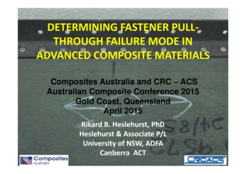
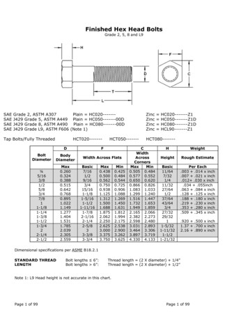
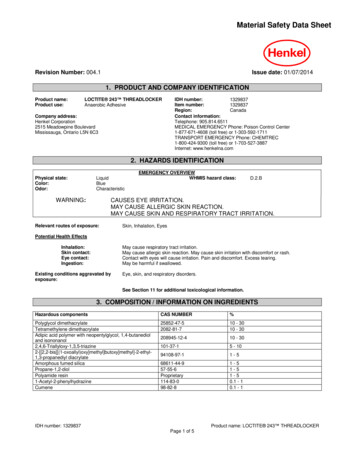
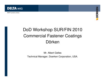
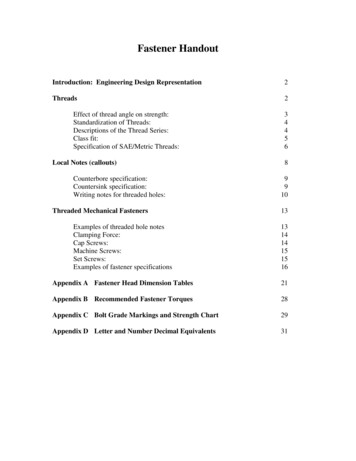
Fig. 1 Thread Profile (External)Major Diameter - the largest diameter of the threadMinor Diameter - the smallest diameter of the threadCrest– the peak of the thread for external threads, the valley of the thread forinternal threadsPitch Diameter – nominally the mean of the major and minor diametersThread Angle – The included angle between two adjacent thread walls.Effect of thread angle on strength:The lower the value of the thread angle, the greater the loadcarrying capability of the thread.The force of mating threads is normal to the surface of the thread.This is shown in the figure as F. The components of the force Ftransverse and parallel to the axis are shown as Ft and Fa. Thecomponent of force typically responsible for failure is that appliedtransverse to the axis of the thread. It is this load that can cause3Fig. 2 Thread Forces
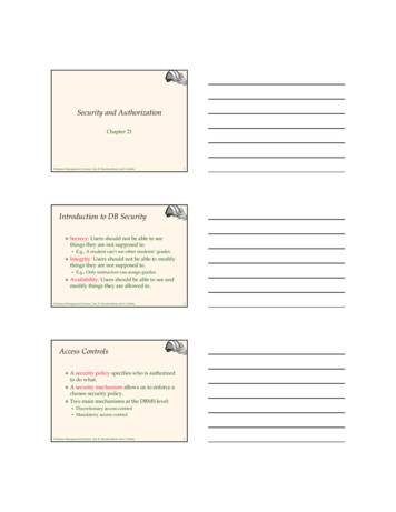
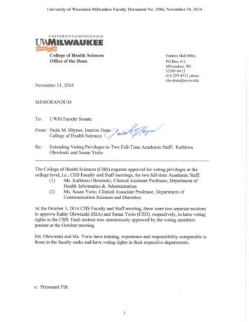
cracking in internal threads, especially under cyclic loads. Internal threads are moresusceptible since they are typically cut and cutting operations in metals produce surfaceirregularities that can contribute to crack growth. External threads are typically rolledonto a fastener and therefore lack the surface flaws of cut threads. As the thread angledecreases, the component Ft gets smaller. This is why square and buttress threads areusually used for power transfer applications.Standardization of Threads: (Standard Inch Units)To facilitate their use, screw threads have been standardized. In 1948, the United States,Great Britain and Canada established the current system for standard inch dimensionthreads. This is the Unified thread series and consists of specifications for UnifiedCoarse (UNC) Unified Fine (UNF) and Unified Extra Fine (UNEF) threads. Metricthreads are also standardized. Metric thread specification is given through ISO standards.Thread information is available in tabular form from many sources including MechanicalDrawing texts and Machine Design handbooks.Thread form:Thread form is a classification based upon the cross-sectional profile of the thread. Thestandard thread form for inch unit threads in U.S. is the Unified (UN) thread form. Thisthread form is characterized by a 60 degree thread angle and a flat crest and rounded root.Thread series:Thread series is a standard based upon the number of threads/inch for aspecific nominal diameter. Standards for standard inch units are:Coarse (C), Fine (F), Extra-Fine (EF). The figure at right shows fineand coarse thread fasteners. The designation is based upon the numberof threads per unit length. A short discussion of each thread series isgiven below.Threads per Inch:Fig. 3 Course, FineThreadsLiterally a measure of the number of crests per unit of length measuredalong the axis of the thread. The number of threads/inch for a threadseries is given by standard and may be found in thread tables. The TapChart shown later in this document gives the number of threads/inchbased upon threads series and nominal diameter.Fig. 4 Threads per Inch4
Descriptions of the Thread Series:Unified Coarse. UNC is the most commonly used thread on general-purposefasteners. Coarse threads are deeper than fine threads and are easier to assemblewithout cross threading. UNC threads are normally easier to remove whencorroded, owing to their sloppy fit. A UNC fastener can be procured with a class3 (tighter) fit if needed (fit classes covered below).Unified Fine. UNF thread has a larger minor diameter than UNC thread, whichgives UNF fasteners slightly higher load-carrying (in shear) and better torquelocking capabilities than UNC fasteners of the same material and outsidediameter. The fine threads have tighter manufacturing tolerances than UNCthreads, and the smaller lead angle allows for finer tension adjustment. UNFthreads are frequently used in cases where thread engagement is minimized due tothinner wall thickness.Unified national extra fine. UNEF is a thread finer than UNF and is common tothe aerospace field. This thread is particularly advantageous for tapped holes inhard materials as well as for tapped holes in thin materials where engagement is ata minimum.Class fit:Class fit is a specification of how tightly mating external and internal threads will mesh.It is based upon the difference in the values of the respective pitch diameters. Thesedifferences are in the thousandths of an inch. For the Unified thread form, the classes offit are:Class 1:Loose fit. Threads may be assembled easily by hand. Used incases where frequent assembly/disassembly required. Typicallyrequire use of locking devices such as lock washers, locking nuts,jam nuts, etc. Class 1 fits are common for bolts and nuts.Class 2:Standard fit. Threads may be assembled partly by hand. Mostcommon fit in use. Used in semi-permanent assemblies.Class 3:Tight fit. Can be started by hand, but requires assistance (tools) toadvance threads. Common for set screws. Used in permanentassemblies.An additional designation is made for external (A) versus internal (B) threads andis included as a postscript to the numerical designation.5
Examples:Standard inch unit thread specification.4375 - 20UNF - 2A, LH.500 - 13UNC – 1A.375 - 24UNEF - 2BSpecification of Metric Threads:Metric threads are defined in the standards document ISO 965-1. Metric threadspecifications always begin with thread series designation (for example M or MJ),followed by the fastener’s nominal diameter and thread pitch (both in units ofmillimeters) separated by the symbol "x".Examples:Metric thread specificationMJ6 x 1 - 4H5HM8 x 1.25 - 4h6h LHM10 x 1.5 - 4h5h6
Metric thread series:There exist multiple metric thread series used for special applications. The standard isthe M series. The MJ series is one of the most common of the special applicationthreads.M Series: Standard metric thread profileMJ Series: Modified series in which crest and root radii are specifiedMetric thread fits:A fit between metric threads is indicated by internal thread class fit followed by externalthread tolerance class separated by a slash; e.g., M10 x 1.5-6H/6g. The class fit isspecified by tolerance grade (numeral) and by tolerance position (letter).General purpose fit6g (external)Close fit5g6g (external)6H (internal)6H (internal)If thread fit designation (e.g., "-6g") is omitted (e.g., M10 x 1.5), it specifies a"medium" fit, which is 6H/6g. The 6H/6g fit is the standard ISO tolerance classfor general use.English unit internal and external thread class fit 2B/2A is essentially equivalentto ISO thread class fit 6H/6g. English unit class fit 3B/3A is approximatelyequivalent to ISO class fit 4H5H/4h6h.Default metric fastener thread pitch. If metric thread pitch designation (e.g., " x 1.5")is omitted, it specifies coarse pitch threads. For example, M10 or M10-6g, by default,specifies M10 x 1.5. The standard metric fastener thread series for general purposethreaded components is the M thread profile and the coarse pitch thread series.Metric fastener thread series compatibility. Metric fastener thread series M is thecommon thread profile. Thread series MJ designates the external thread has an increasedroot radius (shallower root relative to external M thread profile), thereby having higherfatigue strength (due to reduced stress concentrations), but requires the truncated crestheight of the MJ internal thread to prevent interference at the external MJ thread root. Mexternal threads are compatible with both M and MJ internal threads.7
Metric Thread ExampleM10 x 1.5-6g means metric fastener thread series M, fastener nominal size(nominal major diameter) 10 mm, thread pitch 1.5 mm, external threadclass fit 6g. If referring to internal thread tolerance, the "g" would beuppercase.Left Hand Threads:Unless otherwise specified, screw threads are assumed to be right-handed. This meansthat the direction of the thread helix is such that a clockwise rotation of the thread willcause it to advance along its axis. Left-handed threads advance when rotated counterclockwise. Left-handed threads are often used in situations where rotation loads wouldcause right-hand threads to loosen during service. A common example is the bicycle.The pedals of a bicycle are attached to the crank arm using screw threads. The pedal onone side of the bicycle uses right-hand threads and the other uses left-hand. This preventsthe motion of pedals and crank from unscrewing the pedal and having it fall off duringuse. Left-hand threads must be indicated in the thread specification. This isaccomplished by appending “LH” to the end of the specification.Local NotesLocal notes, also referred to as callouts, are included on adrawing to specify information for a specific feature of acomponent or assembly. The feature being referenced isindicated through the use of a leader line. The leader linepoints to the feature in question and terminates at the note.One common example of a local note is the specification ofthe size dimension of a hole feature.When a callout is made to a hole feature, the leader lineshould reference the circular view of hole with line pointingtoward the center of the circle. The note should be written inFig. 5 Callout Examples8
the order of operations performed. (e.g. drill then thread)and the leader arrowhead should touch the representationof the last operation performed.Fig. 6 Common Callout SymbolsFig. 7 Counterbored and Countersunk HolesThe two examples of callouts below reference counterbored and countersunk holes. Incase you have forgotten, counterboring and countersinking are secondary machiningoperations used to create cylindrical and conical (respectively) enlargements of a hole,usually for the purpose of recessing a fastener head.In the examples shown at right the pilothole is specified first then thecounterbore or countersink is specified.Notice that no specification of operationis given for the pilot hole. Operationspecifications such as “DRILL” or“BORE” are no longer included in notesand callouts. Rather only the featuresizes (and tolerances, if applicable) areincluded.Fig. 8 Counterbore and Countersink Callouts9
Counterbore specification:Include the diameter of the counterbore, which is based upon fastener head diameterwith a clearance value added. ( Refer to Head Dimension Tables, Appendix A forthis information )Include the depth of the counterbore, which is based upon head profile height.( Refer to Head Dimension Tables, Appendix A for this information )Countersink specification:Include the angle of countersink and either;1) depth of countersinkor2) diameter of maximum opening (basedupon fastener head diameter plus 1/64typ. or equivalent)Examples of metric notes for counterbored,countersunk and spot-faced holes are given at right.Fig. 9 Metric Notes for Counterbored,Countersunk and Spotfaced Holes.The depth of a machined hole is categorized as being either thru orblind. A thru hole begins at the penetrating surface and terminates atanother surface. Therefore the “depth” of the hole is based upon thedistance between the two surfaces. Because of this, the thru holerequires no specification of depth in the no
followed by the fastener’s nominal diameter and thread pitch (both in units of millimeters) separated by the symbol "x". Examples: Metric thread specification MJ6 x 1 - 4H5H M8 x 1.25 - 4h6h LH M10 x 1.5 - 4h5h . 7 Metric thread series: There exist multiple metric thread series used for special applications. The standard is the M series. The MJ series is one of the most common of the special .