Transcription
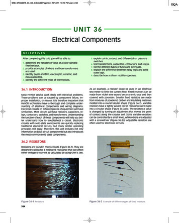
M36 STAN9615 03 SE C36.indd Page 564 29/12/11 10:13 PM user-s163UNIT 36Electrical ComponentsOBJECTIVESAfter completing this unit, you will be able to:1. determine the resistance value of a color-bandedfixed resistor.2. provide examples of where and how transformersare used.3. identify paper and film, electrolytic, ceramic, andmica capacitors.5. explain cut-in, cut-out, and differential on pressureswitches.6. test transformers, capacitors, contactors, and relays.7. list the different types of fuses and overloads.8. explain the difference between relay logic and solid-state logic.9. describe how a silicon rectifier operates.4. identify the different types of thermostats.36.1 INTRODUCTIONMost HVACR service work deals with electrical problems.These problems can be caused by component failure, improper installation, or misuse. It is therefore important thatHVACR technicians have a thorough and complete understanding of electrical components and wiring diagrams.Electrical circuits on different pieces of equipment will havesimilarities. Most circuits will have resistors, capacitors, relays, contactors, switches, and transformers. Understandingthe function of each of these components will help you better understand how to troubleshoot a circuit. Electroniccircuits with solid-state components are quickly replacingtraditional electrical circuits, but many similar operatingprinciples still apply. Therefore, this unit includes not onlyinformation on basic circuit components but also introducesthe most common solid-state components.As an example, a resistor could be used in an electricaltest meter to limit the current flow. Fixed resistors can bemade from nickel wire wound on a ceramic tube and thencovered with porcelain. Smaller fixed resistors are madefrom mixtures of powdered carbon and insulating materialsmolded into a round tubular shape (Figure 36-2). Variableresistors have a tightly wound coil of resistance wire madeinto a circular shape (Figure 36-3a,b). The resistance valueis changed by turning an adjustment that moves the pointof contact along the circular coil. Some variable resistorscan be controlled by a small knob, while others are adjustedwith a screwdriver (Figure 36-3c). Adjustable resistors areoften used for electronic circuits.36.2 RESISTORSResistors are found in many circuits (Figure 36-1). They aredesigned to allow for a measured resistance that can affecteither voltage or current as calculated by using Ohm’s law.Figure 36-1 Resistors.564Figure 36-2 Example of different types of fixed resistors.
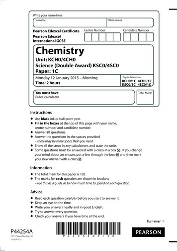
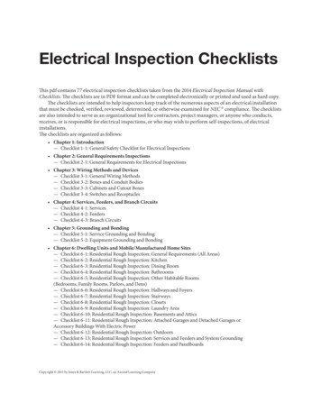
M36 STAN9615 03 SE C36.indd Page 565 29/12/11 10:13 PM user-s163UNIT 36(a)ELECTRICAL COMPONENTS565Figure 36-4 Resistor color-code chart.Figure 36-5 The resistor color code is orange, orange, red,silver.(b)is gold, this will indicate a 0.1 multiplier. The fourth bandindicates tolerance. Silver indicates a /- 10 percent tolerance, and gold indicates a /- 5 percent tolerance. If thereis no fourth band, the resistor tolerance is /- 20 percent.Calculate the resistance of the resistor shown inFigure 36-5. The first band is orange, which is listed asnumber 3 on the chart. The second band is also orange,and the third band is red. The resistance therefore wouldbe 3,300 ohms with a tolerance of 10 percent.36.3 CAPACITORS(c)Figure 36-3 (a) Resistance changes at different points alongthe resistance coil; (b) assortment of variable resistors; (c) asmall, flat-tipped screwdriver would be require to turn theadjustment to change the resistance.Resistor Color BandsMarkings on resistors can vary. Larger resistors have printedresistance values, while smaller resistors have color-codedbands. To determine the resistance of a color-coded resistor, start from the end opposite the silver or gold band.Use the color code chart from Figure 36-4 to determinethe resistance values. The first two bands identify the firstand second digits of the resistance value, and the third bandindicates the number of zeroes. However, if the third band issilver, this will indicate a 0.01 multiplier. If the third bandA capacitor will store energy when an electric charge isforced onto its plates from a power source. A capacitorwill still retain this charge even after disconnection fromthe power source. However, it would be impractical to tryto discharge the power from the capacitor into a differentcircuit, as you would do, for example, by placing chargedbatteries into your radio. Compared to a storage battery,the total amount of energy stored by a capacitor is relativelysmall. Also, the discharge rate of a capacitor is rapid, sothe release of the stored energy only occurs during a shorttime interval. However, a mishandled capacitor will delivera shock that can be severe and even fatal, especially forlarge capacitors charged to a high voltage.Capacitor TypesCapacitors are rated for a maximum voltage by the manufacturer. This rating is usually expressed as the direct current working voltage (DCWV). Exceeding this voltage willshorten the life of the capacitor.Capacitors can be used for a number of different applications. As an example, they can be used for tuning,
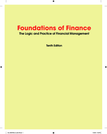
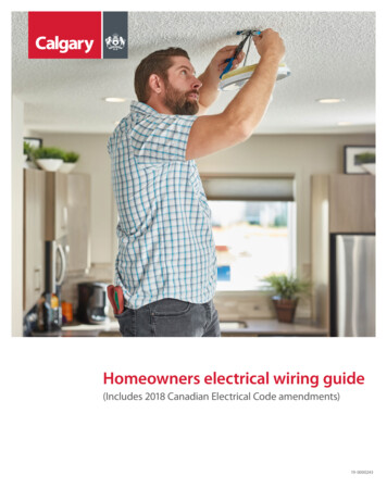
M36 STAN9615 03 SE C36.indd Page 566 29/12/11 10:13 PM user-s163566SECTION 5HVACR ELECTRICAL SYSTEMS AND COMPONENTSFigure 36-8 Rolled film and paper capacitors.Figure 36-6 Disc ceramic capacitors.filtering, energy storage, power factor correction, and motor starting. Capacitive filters are used to smooth pulsatingDC and separate low-frequency AC from high-frequency AC.Capacitive tuners are used for tuning radios and televisionsets to the proper channel. Energy-storage capacitors areused in industrial applications such as capacitor dischargewelding, where a large amount of stored energy is discharged rapidly. The leading current of a capacitor offsetsthe lagging current in an inductive load to allow for powerfactor correction. Many electric motors also utilize capacitors to produce a current phase shift in their windings.Not all capacitors are made of the same materials.There are paper and film, electrolytic, ceramic, and micacapacitors. Disc ceramic capacitors are commonly found onelectronic circuit boards and are typically 0.1 microfarads(mfd) or less (Figure 36-6). Mica capacitors are limited toeven lower values than this (Figure 36-7).For larger-capacitance requirements, paper and filmcapacitors are used (Figure 36-8). They are constructedusing a rolled-foil technique. Once rolled, the capacitor maybe dipped into a plastic insulating material. Capacitors ofthis type used for electronic circuits are rated at generallyless than 1 mfd. However, they can also be designed forindustrial applications to meet the requirements of severalhundred microfarads. In this case, they would be housed ina metal container filled with special insulation oil.Figure 36-7 Mica capacitor.Figure 36-9 Electrolytic capacitors marked for polarity.The type that provides for the most capacitance in relationship to their size and weight are electrolytic capacitors, which are commonly polarized. The polarity is markedon the body of the capacitor in some manner, as shownin Figure 36-9. Never reverse the polarity on this type ofcapacitor. This will lead to excessively high current, overheating, and possible explosion of the capacitor. A pop-outhole on some capacitors allows for the insulation to expandif the capacitor is overheated (Figure 36-10). If the hole isruptured, the capacitor must be replaced.Motor CapacitorsCapacitors for motors are classified as either startingcapacitors or running capacitors. In replacing a capacitor,it is desirable to use an exact replacement. This means acapacitor with the same mfd rating and voltage limit rating.Do not interchange start and run capacitors (Figure 36-11).Start capacitors are high-capacity (50–700 mfd) electrolytic units that are intended for momentary use in startingFigure 36-10 Motor-start capacitor with pop-out hole.
M36 STAN9615 03 SE C36.indd Page 567 29/12/11 10:13 PM user-s163UNIT 36Figure 36-11 Assortment of both motor-start and motor-runcapacitors.ELECTRICAL COMPONENTS567MARKED TERMINALFigure 36-13 The marked terminal on the run capacitor shouldbe connected to the run terminal of the compressor.this arrangement, an internal short circuit to the capacitorcase will blow the system fuses without passing the currentthrough the motor start winding.36.4 TESTING CAPACITORSFigure 36-12 159 to 191 mfd motor-start capacitor.motors (Figure 36-12). They are normally encased in plastic.Run capacitors have much lower capacitance ratings (2–40mfd) but are made for continuous-duty use. They are normally sealed in a metal can.Motor-start capacitors are in series with the start switchand starting winding. This allows for a large phase shift tocreate a good starting torque. Since it is a starting capacitoronly, it is not rated for continuous duty and is limited to abouttwenty starts per hour.Motor-run capacitors are rated for continuous duty andare commonly used for permanent split-capacitor motors.The capacitor is matched to provide a 90 phase shift between current in the auxiliary and main motor windings at80 to 100 percent of rated power. It stores and releasesan electrical charge in the auxiliary winding to increase thecurrent lag between it and the main winding. This is to balance the effective inductance and inductive reactance ofthe windings. The capacitor remains in the circuit the entiretime the motor is running.Some run capacitors have some sort of a mark, usually a red dot, as shown in Figure 36-13, to indicate theterminal that should be connected to the run terminal. WithThe first operation in testing a capacitor is to discharge it.Do not discharge it by shorting out the terminals, as this candamage the capacitor. To avoid electrical shock, the technician should never place fingers across the terminals beforeproperly discharging the capacitor.The proper way to discharge a capacitor is to put it in aprotective case and connect a 20,000 Ω, 2 W resistor acrossthe terminals, as shown in Figure 36-14. Most start capacitors have a bleed resistor across the terminals. This makesit so the capacitor can be tested with the bleed resistor inplace. Even so, it is good practice to make sure the chargehas been bled off.Capacitors can be roughly checked by using an ohmmeter. The ohmmeter used in testing capacitors should beable to read a high resistance and have at least an R * 100scale. To test the capacitor, disconnect it from the wiringand place the ohmmeter leads on the terminals, as shownin Figure 36-15.If the capacitor is not shorted, the needle will makea rapid swing toward zero and slowly return to infinity. Ifthe capacitor has an internal short, the needle will stay atzero, indicating that the instrument will not take the charge.What you are actually doing is attempting to charge the capacitor using the battery in the ohmmeter (be sure the battery in the ohmmeter is good). An open capacitor will readhigh with no dip and no recovery.The use of a capacitor analyzer is highly recommended(Figure 36-16). This instrument will read the mfd rating anddetect any breakdown in the dielectric underload conditions. It will detect any capacitors that have failed to hold
M36 STAN9615 03 SE C36.indd Page 568 29/12/11 10:13 PM user-s163568SECTION 5HVACR ELECTRICAL SYSTEMS AND COMPONENTSTHE NEEDLE JUMPS UPTHEN SLOWLYDROPS BACKDOWNFigure 36-14 Using a bleed resistor on a start capacitor.their ratings. It also is useful in measuring the rating of acapacitor that has an unreadable marking.Most digital multimeters now have scales for testingcapacitors. Set the meter to the capacitance test functionand place the leads on the capacitor terminals (Figure 36-17).Figure 36-15 Using an ohmmeter to test capacitors.36.5 TRANSFORMERSHVACR equipment often requires more than one voltage.One or more transformers are often used to step downthe line voltage to supply load or control requirements.Occasionally a stepup transformer may be used.TECH TIPThere are several reasons that most HVACR equipment uses 24 V as the control voltage. First, under moststate and local guidelines, an electrician’s license is notrequired to install and service these low-voltage wires.Second, most codes do not require that these connections be made at electrical junction boxes. And third,under OSHA regulations, circuits that have less than 80 Vfall under less stringent safety requirements.Figure 36-16 Capacitor test meter.
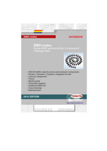
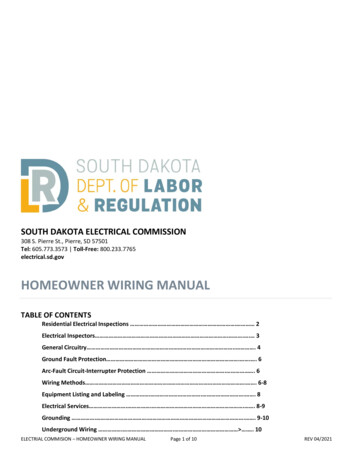
M36 STAN9615 03 SE C36.indd Page 569 29/12/11 10:13 PM user-s163UNIT 36ELECTRICAL COMPONENTS569Figure 36-17 Testing a capacitor using the capacitor testfunction on a multimeter.Figure 36-19 The primary voltage for this transformer dependsupon the tap used.Transformer DesignTransformers are constructed using the induction characteristics of AC power. When current flows through a coil, amagnetic field is produced. When a second coil is placedin the field of the current-carrying coil (primary), electriccurrent can be transferred to the second coil (secondary) (Figure 36-18). The process is made more efficient bywrapping the coils around a common metal core. The voltage transferred is directly in proportion to the ratio of thenumber of turns on the primary coil to the number of turnson the secondary coil. For example, a control transformerwith a 240 V primary winding and a 24 V secondary windinghas a 10:1 ratio: 10 turns of wire in the primary for everyturn in the secondary.More than one secondary coil can be used if additionalvoltages or circuits are required. Likewise, some transformers are made with more than one primary. These multiplewindings can then be connected in series or parallel tochange the voltage or current capability of the transformer.Center-tapped transformers allow for a small changein the windings voltage rating by changing taps. Typicalresidential voltage is 120 V, but this can vary. A center-PRIMARY 120 VOLTS - 40 TURNSSECONDARY 24 VOLTS - 8 TURNSIRON COREFigure 36-20 Variable autotransformer.tapped transformer could be connected to meet varyingrequirements. As an example, a transformer that has multiple primary taps could be connected for 120 V, 208 V, or240 V, depending on the tap used (Figure 36-19). Variableautotransformers also allow for changing the voltage output (Figure 36-20).Three-phase transformers are generally used for threephase power. However, a single-phase transformer foreach leg (three single-phase transformers) would producethe same results.Transformer ApplicationFigure 36-18 Primary and secondary voltages of a step-downtransformer.There are many different types of transformers for manydifferent applications. Large power transformers are designed to operate at electric utility voltages from 115 V toseveral thousand volts (Figure 36-21). A common use forsome smaller transformers is to provide low-voltage AC to
M36 STAN9615 03 SE C36.indd Page 570 29/12/11 10:13 PM user-s163570SECTION 5HVACR ELECTRICAL SYSTEMS AND COMPONENTSFigure 36-23 Stray eddy current flow through the transformercore is reduced by the oxide surface treatment of the laminations.Transformer ConstructionFigure 36-21 Typical line voltage power transformer.rectifiers for conversion to DC. These would be called rectifier transformers. Air-conditioning systems use low-voltagetransformers to provide 24 V AC to control circuits to operate relays and solenoids. These step down the voltage fromline voltage to 24 V and are referred to as control transformers (Figure 36-22).Equipment that is very sensitive to voltage changesuse constant voltage transformers. Electronic devices mayuse the metal chassis where components are mountedas a common conductor. If you touch the metal chassisaccidently while there is power, you will receive a shock.Isolation transformers are used to break the circuit andprotect the technician.Figure 36-22 Control voltage transformer.Transformers will heat up during operation. This productionof heat is inefficient. Transformer cores are made of thinsheet-metal strips in the form of a laminate. There are anumber of advantages to using thin sheet-metal strips. Itis far easier to manufacture thin sheets because they canbe stamped, where the thicker material would have to becut. Also, the voltage induced in the core will cause current,called eddy current, to circulate (Figure 36-23). Each metalstrip is insulated with a thin layer of oxide, which resiststhe flow of eddy currents (Figure 36-24). This reduces unwanted current circulation through the core and excessiveheating of the transformer.Transformer OperationThe voltage ratings for transformers are specified by themanufacturer for both primary and secondary windings. Aprimary winding operating at above its rated voltage willoverheat. Current ratings are often only provided for thesecondary winding. This is because the primary windingcurrent capacity cannot be exceeded before the secondary winding. When the current rating of the secondary isexceeded, the voltage output drops below the secondaryvoltage rating. This causes the transformer to heat up,shortening its life.Transformers are commonly rated by volt-ampereratings, abbreviated VA (Figure 36-25). The VA rating is literally the voltage multiplied by the current, amps. VA ratings are used because they apply to any load, whetherresistive, reactive, or combination (impedance). Inductiveloads convert electricity to magnetism. The coils of relays,contactors, and solenoids are all examples of inductiveloads. The current and voltage get out of phase in inductive loads, so the wattage is actually less than the voltstimes the amps. VA ratings show the combined effect ofvolts and amps on the transformer regardless of the typeof load on the transformer.Note that the amp draw of the secondary is muchhigher than the amp draw of the primary. Take, for example, a 48 VA transformer with a 120 V primary and a 24 Vsecondary. The primary current 48 VA/120 V 0.4 amps.The secondary current equals 48 VA/24 V 2.0 amps. Notethat this example ignores the heat given off. This is why the
M36 STAN9615 03 SE C36.indd Page 571 1/6/12 1:21 PM user-s163user-F452UNIT 36ELECTRICAL COMPONENTS571Figure 36-24 Laminations are clearly visible on mosttransformers.Figure 36-26 Residential service entrance panel with theaccess cover open to provide access to the circuit breakerswitches.FUSEFUSEFigure 36-25 Industrial control transformer with a .050 KVArating.secondary winding is made from heavier-gauge wire thanthe primary winding.Efficiencies for transformers are higher when they operate more fully loaded. The primary winding current is mostlyinductive, making it nearly as much as 90 out of phase withthe voltage. The mostly resistive secondary winding currentwill offset this at higher transformer loads so that the total current is more in phase with the voltage and thereforemore efficient. When operating without a load, all the current the transformer draws is waste. When operating fullyloaded, most of the current is going to the load.FUSESYMBOLSFigure 36-27 A cartridge fuse and its common symbols.that is placed in series with a load and melts when excessivecurrent flows through it, opening the circuit. Fuses are available in different types and sizes so that they can be selectedto match the requirements of specific loads (Figure 36-28). Ifthey are too small, they melt before they should. If they aretoo large, they do not offer the proper protection. Their selection follows the rules set forth in the electrical code or in thespecifications accompanying the load.36.6 FUSESWhere the power comes into the building, it enters a service entrance panel for distribution to the various electricalloads (Figure 36-26). Each electrical circuit that comes fromthis panel is electrically protected by either a fuse or a circuit breaker.A sample fuse and two commonly used fuse symbols areshown in Figure 36-27. A fuse is a special electrical conductorFigure 36-28 Fuses located in an air-conditioning console.
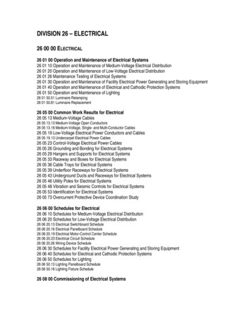
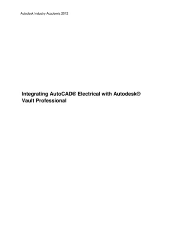
M36 STAN9615 03 SE C36.indd Page 572 29/12/11 10:13 PM user-s163572SECTION 5HVACR ELECTRICAL SYSTEMS AND COMPONENTSFigure 36-29 250 volt fuses: 30 amp on left and 60 ampon right.Cartridge fuses are the most common in HVACR. Theyare rated by voltage, current, and maximum instantaneouscurrent. All their values should be matched when replacinga fuse. Fuses are grouped by physical size. Up to 30 ampsis one physical size; over 30 amps and up to 60 amps is alarger size (Figure 36-29). Fuses are also rated for voltage.Fuses designed for 600 volts are much larger than fusesdesigned for 250 volts (Figure 36-30). Fuses must withstandincredibly high amounts of energy when they are subjectedto a direct short. Not all fuses have the same ability towithstand the same levels of energy. Less expensive fuseshave lower instantaneous current ratings. The two fusesin Figure 36-31 are both 600 V, 30 A fuses, but the one onthe right has a rating of only 50,000 amps while the one onthe left can withstand 200,000 amps. The fuse on the rightwould literally explode if it were subjected to 200,000 amps.Because motors draw four to five times their normal operating current when they start, standard fuses often blowduring normal motor operation. Where fuses are used to protect motors in the circuit, a special type of fuse is used calleda dual-element time-delay fuse. This type of fuse has a builtin delayed action that will tolerate momentary heavy startingcurrent on motor power-up but functions the rest of the timeto protect the motor against excessive running current.Figure 36-30 Both fuses are rated at 30 amps. The larger oneis rated at 600 V, while the smaller one is rated at 250 V.Figure 36-31 Even though both fuses are 600 V 30 amp fuses,the fuse on the left has an IR rating of 200,000 amps, while thefuse on the right has an IR rating of 50,000 amps.CODE TIPUL requires a dual-element time-delay fuse to withstand500 percent of the fuse amp rating for 10 seconds.Dual-element fuses achieve the time delay by using twoseparate elements: one for short circuit protection andanother for overload protection.36.7 CIRCUIT BREAKERSAll residences have some type of electrical panel, wherethe electrical service enters the building and is distributedto the circuits in the building. Each circuit has some typeof protective device to automatically disconnect the powerin case the circuit is overloaded. This protection can eitherbe a fuse as described above or a circuit breaker. Note thesymbols used to represent a circuit breaker in an electricalwiring diagram (Figure 36-32). The advantage of a circuitFigure 36-32 A circuit breaker and its common symbol.
M36 STAN9615 03 SE C36.indd Page 573 29/12/11 10:13 PM user-s163UNIT 36ELECTRICAL COMPONENTS573Figure 36-35 This proximity switch is operated by somecontrolled mechanical movement.Figure 36-33 Small power switch.breaker over a fuse is that it can be manually reset at theelectrical service panel after an overload, rather than replaced. Also, the circuit can be manually opened in casethere is a need to perform service on the circuit. Threetypes of breakers are available: standard, GFCI, and AFCI.Standard breakers protect circuits against too much current, but they cannot detect if current is going where itshould not go. In addition to protecting against too muchcurrent, ground fault circuit interrupter (GFCI) breakers protect against current that flows somewhere outside of thenormal current path. An arc fault circuit interrupter (AFCI)protects against electrical arcs.36.8 SWITCHESSwitches can come in all shapes and sizes (Figure 36-33).Often they are normally open and when the switch positionis changed from OFF to ON, the switch contacts will closeand energize a circuit, the same as when you turn on a light.Switches can also be designed to be normally closed, whichde-energizes the circuit when the contacts open (Figure36-34). An example would be a stop switch to shut down amotor. Proximity switches often limit motion and are oftenoperated by the movement of a mechanical device (Figure36-35). An example would be a switch that stops the motorused for opening air inlet dampers once they have reacheda full open position.General-duty switches are designed for use in residential and commercial applications. These are used for relativelyFigure 36-34 The black switch is pushed to start (normallyopen), while the red switch is pushed to stop (normally closed).Figure 36-36 Residential safety switch.light-load applications such as general air-conditioning andappliance loads. There are several different kinds of theseswitches, and some will have fuses while some others will not.A typical residential safety switch is shown in Figure 36-36.Switches are rated by the voltage and current they can safelyswitch (Figure 36-37). Operating a switch on a higher voltageor heavier current than its rating is dangerous.Air-conditioning systems use many switches that openand close based on a particular condition. Examples includethermostats that open and close based on changes in temperature, humidistats that open and close based on changesFigure 36-37 This switch is rated for 120 V and 15 amps.
M36 STAN9615 03 SE C36.indd Page 574 29/12/11 10:13 PM user-s163574SECTION 5HVACR ELECTRICAL SYSTEMS AND COMPONENTSin humidity, and pressure switches that open and close basedon changes in pressure. These can be divided into two general categories: line voltage and low voltage. Line-voltageswitches are referred to as line duty, while low-voltageswitches are referred to as pilot duty.THERMISTOR36.9 LOW-VOLTAGE THERMOSTATSA thermostat is a switch that is operated based on changesin temperature. Low-voltage thermostats operate on 24volts and normally do not switch more than 2 amps. Lowvoltage thermostats typically control several system functions. They operate like a bunch of switches, each one witha specific function. However, instead of operating the system by manually flipping all the appropriate switches, thethermostat does it automatically for you.Low-voltage thermostats have two manual switches: asystem switch and a fan switch. The system switch controlsthe operating mode: Off, Cooling, Heating (Figure 36-38).The fan switch controls cycling of the fan. In the ON position, the fan operates all the time, regardless of the thermostat setting. In the AUTO position, the fan cycles with thesystem (see Figure 36-38).For many years, thermostats were electromechanical,using bimetal coils to move mercury bulb switches (Figure36-39). The bimetal element is composed of two differentmetals bonded together. As the temperature surrounding theelement changes, the metals will expand or contract. SinceFigure 36-38 The system switch and fan switch on a typicallow-voltage thermostat.Figure 36-39 Older bimetal element and mercury bulbthermostat.Figure 36-40 Thermistor sensor used in electronic thermostat.the metals have different coefficients of expansion, one willexpand or contract faster than the other. This creates movement in the bimetal such as twisting or turning. A mercurybulb attached to the bimetal acts as a switch. The contacts areenclosed in an airtight glass bulb containing a small amount ofmercury. When the bimetal tilts the bulb, mercury in the bulbwill roll to one end and complete the electrical circuit.Newer low-voltage thermostats are now digital, usingthermistors to sense the temperature and logic to controlthe operation of electronic switches or relays inside thethermostat (Figure 36-40). Electronic digital thermostatsare considerably more accurate than older electromechanical thermostats. They will control the temperature within1 F, while the bimetal thermostat controls to an accuracyof about 3 F. Digital thermostats require voltage to operatetheir logic boards. Some require both sides of the 24 V control power to operate, others steal power from the circuitsthey are controlling, and many use batteries. Some maywork with either 24 volts or batteries.Many thermostats are now touchscreen units with noactual switches at all (Figure 36-41). However, they still retainthe same basic functions of the old electromechanical thermostats. They still have a virtual system switch that selectsthe system operating mode and a virtual fan switch to selectcontinuous operation or automatic cycling (Figure 36-42).System operation is controlled by energizing terminalsthat energize different parts of the unit. Because the operation of furnaces and heat pumps are quite different, thermostats are normally designed to control furnaces and airconditioners, or they are designed to control heat pumps.However, many digital thermostats now will work with furnaces, heat pumps, or a combination of both depending uponthe thermostat configuration. The specific terminals that areenergized in heating or cooling operation and the way theycycle are determined by the thermostat configuration. Figure36-43 shows a configuration screen from a touchscreen thermostat that can be configured for many types of systems.
M36 STAN9615 03 SE C36.indd Page 575 29/12/11 10:13 PM user-s163UNIT 36Figure 36-41 Touchscreen thermostats have no physicalswitches.Figure 36-42 Virtual fan switch and system switch on atouchscreen thermostat.Staging thermostats allow more than one stage ofheating or cooling. In general, operating just the amountof heating or cooling necessary saves energy and money.The unit can use less energy by operating on first stage at alower capacity most of the time. Heat pump systems typically use the second stage of heat to control auxiliary heat.If the first stage cannot meet the demand, a second stageis energized. Many two-stage furnaces are now availablewith low-fire and high-fire operation. Air conditioners andheat pumps are also commonly available with two capacitycompressors. Staging thermostats are required for all theseapplications. Often, a configurable staging thermostat isused so that the thermostat function can match the systemneeds. More details on low-voltage thermo
UNIT 36 ELECTRICAL COMPONENTS 567 this arrangement, an internal short circuit to the capacitor case will blow the system fuses without passing the current through the motor start winding. 36.4 TESTING CAPACITORS The first operation in testing a capacitor is to discharge it. Do no