Transcription
PROJECT NO.4650BInstallation Guide for iPVC Pipe
Installation Guide for iPVC PipePrepared by:David M. HughesAmerican WaterChandan VenkateshAmerican WaterMohammad NajafiCenter for Underground Infrastructure Research and Education, University of TexasandAmeya Brahmanand ParadkarCenter for Underground Infrastructure Research and Education, University of Texas2018Co‐Sponsored by:American Water 2018 The Water Research Foundation. ALL RIGHTS RESERVED
The Water Research Foundation (WRF) is a nonprofit (501c3) organization that provides a unified source for OneWater research and a strong presence in relationships with partner organizations, government and regulatoryagencies, and Congress. WRF conducts research in all areas of drinking water, wastewater, stormwater, and waterreuse. The Water Research Foundation’s research portfolio is valued at over 700 million.WRF plays an important role in the translation and dissemination of applied research, technology demonstration, andeducation, through creation of research‐based educational tools and technology exchange opportunities. WRF servesas a leader and model for collaboration across the water industry and its materials are used to inform policymakersand the public on the science, economic value, and environmental benefits of using and recovering resources foundin water, as well as the feasibility of implementing new technologies.For more information, contact:The Water Research FoundationAlexandria, VA Office1199 North Fairfax Street, Suite 900Alexandria, VA 22314‐1445Tel: 571.384.2100www.werf.orgwerf@werf.orgDenver, CO Office6666 West Quincy AvenueDenver, Colorado 80235‐3098Tel: 303.347.6100www.waterrf.orgInfo@WaterRF.org Copyright 2018 by The Water Research Foundation. All rights reserved. Permission to copy must be obtainedfrom The Water Research Foundation.WRF ISBN:978‐1‐60573‐337‐1WRF Project Number: 4650BThis report was prepared by the organization(s) named below as an account of work sponsored by The WaterResearch Foundation. Neither The Water Research Foundation, members of The Water Research Foundation, theorganization(s) named below, nor any person acting on their behalf: (a) makes any warranty, express or implied,with respect to the use of any information, apparatus, method, or process disclosed in this report or that such usemay not infringe on privately owned rights; or (b) assumes any liabilities with respect to the use of, or for damagesresulting from the use of, any information, apparatus, method, or process disclosed in this report.Prepared by American Water and Center for Underground Infrastructure Research and Education, University ofTexasThis document was reviewed by a panel of independent experts selected by The Water Research Foundation.Mention of trade names or commercial products or services does not constitute endorsement or recommendationsfor use. Similarly, omission of products or trade names indicates nothing concerning The Water ResearchFoundation's position regarding product effectiveness or applicability. 2018 The Water Research Foundation. ALL RIGHTS RESERVED
CONTENTSLIST OF FIGURES . vLIST OF TABLES . viiCHAPTER 1: GENERAL INFORMATION. 11.1 Sizes, Specifications, and Pressure Ratings of iPVC Pipe. 11.2 Pressure Ratings . 21.3 Marking . 31.3.1 PVC Pipe Marking . 3CHAPTER 2: SAFETY . 52.1 Personal Safety. 52.2 Personal Protective Equipment . 52.3 Job Site Safety. 52.4 Notification to Work Safely . 62.5 General Precautions and Practices . 6CHAPTER 3: RECEIVING, STORING, AND HANDLING iPVC PIPE . 73.1 Receiving . 73.2 Handling Precautions . 73.3 Handling Recommendations . 73.3.1 Unloading Equipment . 83.3.2 Cold Weather Handling . 83.4 Storing . 93.4.1 Warehouse Storage . 93.4.2 Job Site Storage Guidelines . 93.4.3 Outdoor Storage . 9CHAPTER 4: INSTALLATION . 114.1 iPVC Pipe Installations . 114.1.1 Design . 114.1.2 Installation. 114.1.3 Installation in Contaminated Soils . 144.1.4 Field Tasks . 144.2 Tapping for Service Connections. 174.3 Summary of Installation Guidelines for iPVC Pipe . 18CHAPTER 5: COMMISSIONING. 215.1 Initial Pipe Testing . 215.2 Flushing. 215.3 Filling . 215.4 Hydrostatic Testing and Leak Testing . 215.5 Disinfection . 22iii 2018 The Water Research Foundation. ALL RIGHTS RESERVED
APPENDIX A: FREQUENTLY ASKED QUESTIONS . 23APPENDIX B: CHECKLIST . 27REFERENCES . 29ABBREVIATIONS . 31iv 2018 The Water Research Foundation. ALL RIGHTS RESERVED
LIST OF FIGURES1.1 PPI manufacturer marking configuration on PVC pipe . 33.1 Loading and unloading using forklift . 84.1 Typical cross-section of trench and backfilling for PVC installation . 144.2 iPVC pipe cutting using power tool . 154.3 Surface preparation and lubrication of the pipe ends. 154.4 Insertion reference marking on the spigot end of the pipe. 164.5 Joining the pipe - mechanical (A) and manual joining (B) . 174.6 Appropriate saddle for proper connection . 184.7 Tapping machine with feed nut and yoke . 18v 2018 The Water Research Foundation. ALL RIGHTS RESERVED
2018 The Water Research Foundation. ALL RIGHTS RESERVED
LIST OF TABLES1.1 iPVC pipe specifications . 11.2 Properties of iPVC pipe . 2vii 2018 The Water Research Foundation. ALL RIGHTS RESERVED
2018 The Water Research Foundation. ALL RIGHTS RESERVED
CHAPTER 1GENERAL INFORMATIONPolyvinyl Chloride (PVC) pipes were first manufactured in Germany in 1935 and wereintroduced in the United States in 1952. Today, it has become one of the world’s most widely usedand recognized thermoplastic pipe materials. Due to its engineering properties, PVC pipe can befound in different business applications such as pressure-rated gas and oil, recycled water, sanitaryand drinking water pipeline systems.Reported benefits of PVC pipe include the following 1.1Resistance to Aggressive Environment– PVC pipe has shown resistance to rusting,pitting, corrosion, tuberculation or supporting biological growth and too manychemical compounds.Life Cycle and Construction Cost Savings – For utility applications, the life cycle andconstruction cost of PVC pipe can be significantly less than other pipe materials.Properties such as comparatively light weight, ductility and flexibility facilitate uniqueand cost-effective installation applications. Its aforementioned resistance to corrosionprovides expectation of a long life in many environments.Durability –PVC pipe installations are cost-effective and have long-term costadvantages due to the pipe’s physical properties, and reduced maintenance costs(corrosion, leaching).Permeation –PVC offers greater permeation resistance for gasoline and water solutionssuch as benzene and toluene than Polyethylene (PE) pipe (Uni-Bell, 2012)SIZES, SPECIFICATIONS, AND PRESSURE RATINGS OF IPVC PIPEThe iPVC pressure pipe is manufactured using ASTM D1784 PVC compounds and cellclassification 12454 materials. The iPVC pipes are available in diameters 4, 6, 8, 10 and 12 inchesand manufactured in accordance to with AWWA C900 and ISO guidelines. These pipes arecurrently being manufactured by Pyungwha Pipe Inc. (PPII) in South Korea and are sold in Korea,China, and Japan. Pipe specifications are shown in Table 1.1.Table 1.1iPVC pipe specificationsO D (inch)Wall Thickness (inch)DR 14DR 18DR 25Pipe Size(inch)AverageTolerance44.8 0.0090.3430.04130.2670.0322.40.1920.0231.766.9 0.0110.4930.0596.10.3830.0464.860.2760.0333.689.05 1 .2 um ToleranceWeight(lbs/ft)Minimum ToleranceWeight(lbs/ft)Minimum ToleranceWeightLength(lbs/ft)20 ft 1 in.Source: Data from PPIITable 1.2 compares testing results from iPVC pipe in comparison to the AWWA C900standard.1 2018 The Water Research Foundation. ALL RIGHTS RESERVED
Table 1.2Properties of iPVC pipeEngineering PropertiesAWWA C900 Pipe(JM Eagle, 2016)iPVC PipeTensile Test at 73 F7000 psi7,930 psiModulus of Elasticity400,000 psi461,000 psiImpact Test at 73 F200 foot poundsHydrostatic burst test755 psiPipe StiffnessNo failure5 Second Burst Test364 psi73Ԭ, 500 psi,1000 hours73Ԭ, 470psiNo failurePassAcetone Immersion Test20 minutesNo crackingPassVice Flattening TestNo CracksNo CracksPassTemperature of Deflection-PassFlammability Test-PassIzod Impact Test / 73 degrees F-HDS Testing 2000h / 10000h-Sustained Pressure TestWorking pressure73º F (% of rating at 73º F)80º F (% of rating at 73º F)100º F (% of rating at 73º F)Manning N Value451 psi13% increase in strength over thestandard15% more ductile than thestandardAt least 12 times more resilientthan the standard37% higher than the standard24% more stiffer than the standardPassPass4200 psiPass100%88%52%67x10-5in/inch/degree FCoefficient of thermal expansionCoefficient of flow1,200 footpounds nofailure1,030 psiRemarksC 150N 0.009Slightly higher than conventionalPVC but lower than comparablePE pipeC 150Standard PVC valueN 0.009Standard PVC valueThe following is a partial summary of the PVC standard documents applicable to iPVCpressure pipe. 1.2C605 - Underground Installation of Polyvinyl Chloride (PVC) and MolecularlyOriented Polyvinyl Chloride (PVCO) Pressure Pipe and FittingsC900 - Polyvinyl Chloride (PVC) Pressure Pipe and Fabricated Fittings, 4 inch through60 inch (100 mm through 1,500 mm), for Water Transmission and DistributionAWWA Manual M23 - PVC Pipe - Design and InstallationPRESSURE RATINGSThe iPVC pipes are manufactured to meet or exceed AWWA Standard C900. The AWWAstandard established pressure ratings of PVC pipe as a function of the dimension ratio (DR) of thepipe. Presently the iPVC is manufactured as DR 14, DR 18, and DR 25 pipe.2 2018 The Water Research Foundation. ALL RIGHTS RESERVED
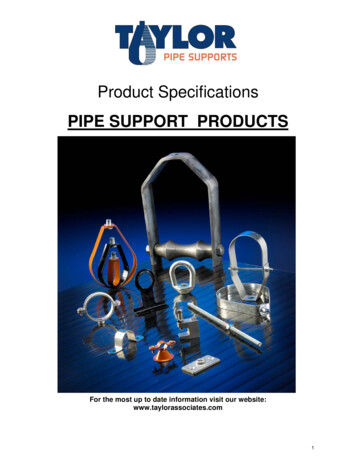
1.31.3.1MARKINGPVC Pipe MarkingIt is mandatory for all the manufacturers to label the PVC pipe wall at frequent intervals tobe compliance with ASTM, AWWA, and NSF standards. Typically labeling will be made on theexterior surface of each pipe segment. PPI imprints the following items of information on everyiPVC pipe (see Figure 1.1): The manufacturer’s name or trademarkThe nominal pipe size (e.g., 8-inch);The type of PVC material (e.g., D17454)The pipe dimension ratio or the pipe pressure rating or AWWA pressure class for 73 F water, or both (PC 235)The standard against which the pipe has been made and tested (AWWA C900)Production record coding the place and time of manufactureThe seal or mark of the certification agency that has determined the suitability of thepipe for potable water service (NSF 61)In addition, the pipe should have a solid circumferential line drawn on the spigot end toshow to extent of the insertion into the adjoining bell at installation.Source: Courtesy of American Water.Figure 1.1 PPI manufacturer marking configuration on PVC pipe3 2018 The Water Research Foundation. ALL RIGHTS RESERVED
2018 The Water Research Foundation. ALL RIGHTS RESERVED
CHAPTER 2SAFETY2.1PERSONAL SAFETYSafety is the highest priority and field personnel should take responsibility for their ownpersonal safety and their fellow installation crewmembers. It is always recommended to wearappropriate personal protective equipment (PPE) on the job and to be aware of the potentialhazards working with pipe. Potential hazards of the operation, materials, equipment, andenvironment should be established before work begins, and plans should be made to minimizethese hazards. Proper highway safety programs must be identified and in operation at all times.For more information, please refer to appropriate safety guidelines provide by the installer, themanufacturer and OSHA.2.2PERSONAL PROTECTIVE EQUIPMENTPPE materials, hard hats, safety vests and steel-toed/composite-toed safety shoes arerequirements at the job site. Workers must wear hard hats, vests, eye-protection, gloves, andrecommended safety shoes during loading or unloading iPVC pipe and fittings in storage areasand pipe yards, during installation, operating the equipment and other areas where overheadhazards and low overhead clearance exist. Steel-toed/recommended composite toed safety shoesshould be worn at all times. While using pneumatic tools such as pavement breakers and tampingmachines, proper eye protection, gloves and ear protection must be employed. When cutting,trimming, or tapping pipe, safety glasses and gloves must be worn. Safety vests must be worn byall the project participants including engineers, consultants, and inspectors while on job siteespecially when working near traffic or at night. Long sleeve clothing should be worn when neededto protect from sunburn.2.3JOB SITE SAFETYBefore work begins at the job site, the potential hazards should be identified and discussedwith the crew and observers on the job. Check the work site for hazards created by unguardedmachinery, chemicals and fuels, heat, excessive noise, nearby equipment, existing buried pipes,cables and or power lines. Specific plans should be made to minimize such hazards. Documentingthese plans and posting them in a public place may be beneficial to those involved in the operationsand public at large.The public should be restrained from getting to close to the defined work area. Fieldpersonnel should avoid working alone or arrange for periodic safety contacts. Field personnelshould have call numbers at hand when required for emergency medical service and support.The guidelines of OSHA as well as state and local regulatory agencies on trenchconstruction requirements must be followed. The trench should be dug to the required alignmentand depth (or as shown on the contract drawings) or as directed by the supervising engineer.Excessive runs of unsupported open trench should be avoided to minimize such problems as trenchflooding, caving of trench walls and the freezing of the trench bottom and backfill material.Principal considerations in trench construction are trench width, stability of the native soil, stabilityof trench walls and water accumulation in the trench. Ladders are mandated in a deep trench to5 2018 The Water Research Foundation. ALL RIGHTS RESERVED
allow quick exit. The OSHA website and Handbook of PVC Pipe Design and Constructionprovides additional information on the construction practice. The field engineers/ project engineermust verify the desired OSHA certifications of all the workers before they are hired to perform thework. Any injuries or accidents must be logged, reported, and investigated as per OSHA guidelines(Uni-Bell, 2012).Ice, snow, and rain are not harmful to iPVC components but precipitation usually make thejob site more challenging for handling pipe, equipment, and personnel. Unsure footing and tractionrequire greater care and caution to prevent damage or injury. Inclement weather can make pipesurfaces slippery. Workers should not walk on iPVC pipe at any time, but this is especially truewhen your footing is poor (PPI 2009). After heavy rain, if the trench is flooded, use pumps todewater the trench and check the stability of the trench walls before working. Workers mustconsider that plastic pipe can float in water in installations in heavy rain or high water tables.2.4NOTIFICATION TO WORK SAFELYObtain all necessary permits from the local city/county/state agencies and notify theresidents prior commencing the project execution. During execution of the job, provide propersigns, barricades, and traffic control at prominent locations.When cutting the pipe with power equipment, keep feet in the clear and block the pipe soit will not move during cutting. Wear protective equipment and never leave tools lying about. (JMEagle, 2016). Check the power tool wiring if used for proper grounding before the work begins,especially when water is present. When conducting live tapping on the pipe for serviceconnections, use appropriate tapping machine recommended for iPVC pipe (controlled by yokeand feed-nut). Avoid drilling directly to the pipe or tapping tool used on ductile iron pipe. Usinginappropriate tool may induce additional stress on pipe and cause failure. During installation, stayclear from construction equipment such as backhoe, trucks, or loaders etc.2.5GENERAL PRECAUTIONS AND PRACTICESIt is the responsibility of the worker to know and follow safe practices. Safe practices canbe found from equipment suppliers/manufacturers, local authorities with jurisdiction pertaining tooperating safely, and applicable regulations and codes.6 2018 The Water Research Foundation. ALL RIGHTS RESERVED
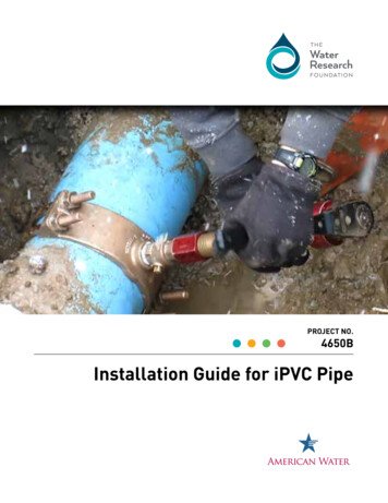
CHAPTER 3RECEIVING, STORING, AND HANDLING IPVC PIPE3.1RECEIVINGiPVC pipes are manufactured in diameters 4 inch and provided in 18-20 foot pipe lengths.Before the pipes are stored in their designated storage areas, the pipes must be inspected. Eachpipe should be inspected for damage with any pipe damaged during the shipping set aside. Checkthe quantities against the shipping list including gasket material and lubricants. Notify themanufacturer/ distributor regarding the damaged or missing pipes.3.2HANDLING PRECAUTIONSIt is the receiver’s (contractor or owner) responsibilities to handle and store the materialproperly pending installation. Once the shipping items are properly off loaded and secured it is theliability of the installer (whether owner or contractor) to handle the pipe, store and install properly.According to PPI’s Field Manual for Municipal Application (2009), practical precautions must befollowed during handling of material: 3.3Only persons directly needed to unload pipe, such as the equipment operator, shouldbe allowed near the unloading area. All other personnel must stay well clear. If thepublic approaches a work area, they must be engaged and properly advised about theconstruction area and where practical should be prevented access by barricade orwarning tape.Use appropriate equipment to unload the pipe.iPVC pipe is slippery when wet. Use caution at all times, especially in rainy or snowyweather.Although iPVC is highly impact resistant, place the pipe carefully on the ground; donot drop the pipe from the truckPrior to receiving material, make sure the unloading area is cleared and properly level(storing in the jobsite) for the pipe.The truck should be parked on level ground wherever possible. If temporary ramps areconstructed to provide a level area, the ramp must be checked before the receiving thematerial.Store only in the designated areas. Pipe should be blocked to prevent rolling.HANDLING RECOMMENDATIONSOff-loading the pipes must be done using appropriate equipment. The equipment must beoperated by experienced operators with sufficient operating space must be available for theoperator and must be free from workers and obstacles. Proper signs boards and signs must beposted in unloading area at the time of off-loading material. If the unloading area becomes busy,additional appropriately attired staff must be used to control the traffic for the unloading period.Equipment operator must have sufficient line of sight and swing radius to operate the equipment.The operator must be aware of the maximum lifting capacity of the equipment and must not lift7 2018 The Water Research Foundation. ALL RIGHTS RESERVED
above designed capacity. Figure 3.1 illustrates typical forklift handling of the iPVC pipe at theconstruction site.Source: Courtesy of American Water.Figure 3.1 Loading and unloading using forklift3.3.1Unloading EquipmentSafe use of unloading equipment is the responsibility of the operator. The procedures forhandling iPVC pipe include: 3.3.2If forklifts are used, check the forks for sharp edges that could damage the iPVC.Remove abrasive locations or use a suitable protective covering to prevent possiblegouging of the pipe;The equipment should be positioned in the widest possible separation;The pipe should be lifted from the center of the pipe at the center of the equipment;Forks/slings should be inserted slowly underneath the pipe; do not twitch or ram them;Operate the forks as close to the ground as possible when moving pipe from onelocation to another, but do not allow the pipe to drag or scrape along the ground. (PPI,2009)Cold Weather HandlingThe engineering properties such as, impact and flexibility are reduced in the coldertemperature and making the pipe material more brittle though in the case of iPVC the differenceis not as impactful as with conventional PVC. It is advised to handle the iPVC pipe properly duringcold weather and assume significant impact while handling can damage the pipe.8 2018 The Water Research Foundation. ALL RIGHTS RESERVED
3.4STORINGThe pipes and its fittings should be inspected visually for any damages and defects beforestoring. As noted previously, any damaged pipe/fittings must be set aside to avoid placing it in thetrench. If the pipe is to be returned to the vendor/distributor, the receiver should note invoice andpacking slip information, parts or batch numbers and the date material was delivered. Damage orquestionable material must not be put into storage or contact the vendor directly for the next steps.Any damage which reduces the pipe wall thickness or properties of pipe may impair long-termservice life has to be discarded.3.4.1Warehouse StoragePipes should be segregated based on pipe size and pressure. Pipe material that can bestacked because of its size or shape should be stored on shelves capable of supporting the combinedweight of the materials. The pipes must be stacked properly in layers with suitable separators usedbetween each row of the stacked pipes. Appropriate end stoppers (bracing) must be provided.3.4.2Job Site Storage GuidelinesJob site storage is recommended when the warehouse/storing place is far from the job site.The pipes must be stored on the level ground; the surface must be free from debris, rocks, or anyother material, which could damage the pipe when placing on the ground. The pipes need to bestored on firm, stable surface. If the ground cannot be made level, use wooden plank or prepare alevelled surface. When pipes of variable wall thickness and size (DR) are received, it isrecommended that the pipe be segregated into piles, each pile containing a single size and pressurerating to minimize confusion later. It is recommended to stack the pipe pile in the shape of pyramidwith the bottom layers properly braced.3.4.3Outdoor StorageiPVC pipes does modestly expand and contract as a function of temperature but not to thesame extent as PE pipe. iPVC pressure pipe can be damaged by prolonged exposure to the sun andthe pipes stored outside for extended time (months) must be covered to protect it from UV rays.9 2018 The Water Research Foundation. ALL RIGHTS RESERVED
2018 The Water Research Foundation. ALL RIGHTS RESERVED
CHAPTER 4INSTALLATIONThe general installation of iPVC pipe and joining are addressed in this chapter. This chapteralso includes overview of bedding, trenching and backfilling methodology followed in the iPVCinstallation. Please use the current AWWA C605, appropriate engineering drawings andspecification for detail procedure.4.14.1.1IPVC PIPE INSTALLATIONSDesignPrior to installation of iPVC pipe the installer must be understand: 4.1.2the scope of the project, location, existing ground conditions and bypass service linesto the customersthe need to inspect pipes and fittings before they are installedthe maximum operating and surge pressure of the system and adequacy of the pipesand fittingssafety issuesInstallationThe iPVC pipes connections are achieved by simple bell and spigot homing. The pipes areclearly marked as to the extent of insertion for the pipe (to avoid over or under insertion). Thispipe is typically installed as an open cut or open trench installation. The iPVC pipes are notrecommended for trenchless application at this time. The open cut is most conventional method ofinstallation pipes. The open cut installation involves the listed:Site PreparationThe site has to be prepared before placing iPVC pipes. Prepare logistic plan, clearing siteincluding obtaining permits from local cities, obtaining location information on other utilities, andrerouting any utility or underground infrastructure before installing the iPVC pipe.TrenchingThe width of the trench is driven by the size of the pipe. As a rule of thumb, the typicaltrench width is 12 inches greater than the outside diameter of the pipe. The trench width and depthare project specific and it is always recommended to refer engineering drawings for trench detailsrelative top depth. If the pipes must be placed below the frost line. The prepared trench must befree from water, dewater using pumps and prepare the trench for installation. If the trench bottomis not sufficient to support the pipe uniformly, proper bedding material must be used to providesupport along the trench bottom. Appropriate cushioning material for the pipe must be providedbetween the hard foundation and the pipe to avoid additional stress on the iPVC pipe. Trench depthshould be adjusted at the bell so the pipe and bell rests uniformly at the bottom of the trench11 2018 The Water Research Foundation. ALL RIGHTS RESERVED
Pipe Placement and ConnectionsThe iPVC pipes are to be handled with proper care regardless of season during handling orlowering the pipe to the trench. Appropriate equipment and lifting accessories (slings, ropes, e
AWWA Manual M23 - PVC Pipe - Design and Installation 1.2 PRESSURE RATINGS The iPVC pipes are manufactured to meet or exceed AWWA Standard C900. The AWWA standard established pressure ratin gs of PVC pipe as a function of the dimension ratio (DR) of the pipe. Presently the iPVC is manuf