Transcription
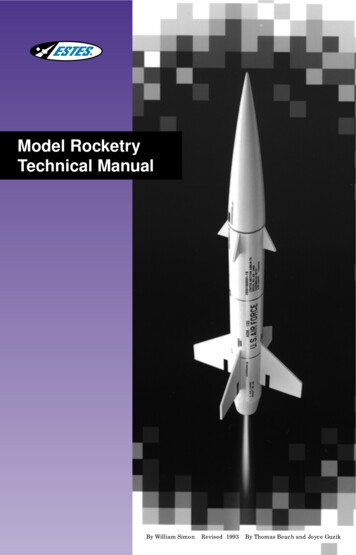
Model RocketryTechnical ManualBy William Simon Revised 1993 By Thomas Beach and Joyce Guzik
INTRODUCTIONWelcome to the exciting world of Estes modelrocketry! This technical manual was written toprovide both an easy-to-follow guide for thebeginner and a reference for the experiencedrocket enthusiast. Here you’ll find the answersto the questions most commonly asked. Morecomplete technical information on all the subjects can be found in the many publicationslisted in your Estes catalog.TABLE OF CONTENTSTopicWhy Estes Model RocketryA Safe ProgramYour First Model RocketConstruction TechniquesTypes of GluesFinishingStabilitySwing Test For StabilityPreparing For FlightIgniter InstallationLaunchingCountdown ChecklistTrackingTrackersRecovery SystemsMulti-StagingClusteringModel Rocket EnginesNAR Safety CodePublicationsPage1111145667788899111213back cover
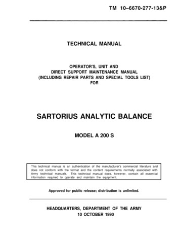
WHY ESTES MODEL ROCKETRY?As your knowledge of rocketry and your modeling skillsincrease you can move up to the Explorer, Challenge, Master,and Pro series models, and eventually to building your own custom designs from parts available in the Estes catalog.The hobby of model rocketry originated at the dawn of thespace age in the late 1950’s. Seeing space boosters carry thefirst artificial satellites into Earth’s orbit inspired many enthusiastic young people to try to emulate the rocket pioneers bybuilding their own rockets. Unfortunately, these homemade“rockets” usually involved stuffing flammable chemicals intometal pipes, very often with tragic results. Newspapers told offingers and eyes lost — and all too frequently of lives lost. Whatwas needed was a safe alternative that would allow young people to experience the thrill of constructing and launching theirown rockets and provide them with the opportunity to explorethe fascinating science of rocketry. Estes model rocketry is theanswer.CONSTRUCTION TECHNIQUESIn the construction of your Estes model rockets you will typically need the following tools and supplies (see kit instructionsfor specific requirements): Modeling knife Scissors Ruler Spray paint Balsa sealer or filler Masking tape Tube-type plastic cement White glue Fine and extra fine sandpaperAlways exercise care when using a modeling knife (they arevery sharp!) and don’t leave the knife laying around after youfinish with it. Use some sort of cutting board under the knife.A smooth, flat piece of board is great; an old phone book orthick catalog also works well on a hard surface. Use newspaper to protect your work surface from accidental glue spills.A SAFE PROGRAMEstes model rocketry is a safe activity because it incorporatesthree important features. The first is the model rocket engine,a professionally manufactured, low cost, solid-fuel rocketengine. This frees the rocket builder from the inherently dangerous procedures of mixing chemicals and packing propellant.The second feature is the use of safe materials for constructing the rockets. All model rockets are built using only lightweight materials such as paper, plastic, and wood. Metal partsare never used for the main structural components of themodel.The third feature is the incorporation of the Model RocketSafety Code into all our flying activities. The safety code provides guidelines for the safe operation of model rockets, suchas launching the rockets electrically from a safe distance, andusing recovery systems to gently return the model to Earth.When the safety code is followed, model rocketry is an extremely safe activity, safer than baseball, soccer, or swimming. Ourhobby’s excellent safety record spans over 35 years and 300million rocket launches.TYPES OF GLUESeveral types of glues and adhesives are commonly used inthe construction of model rockets; the proper glue to usedepends on the application.1. White Glue: This glue works on porous materials such aspaper and balsa. It is a good choice for engine mounts,balsa and fiber fins, launch lugs, paper parts, and forapplying fillets to fin-body joints.2. Aliphatic Glue: Also known as “wood glue” or “carpenter’s glue”; it is usually yellow or tan in color. It is usedjust like white glue, but it is stronger and dries faster.3. Tube-type Plastic Cement: This thick, clear liquid is usedto glue styrene plastic parts to porous materials such aspaper. It is typically used to glue plastic parts to bodytubes. Some E2X series kits use this glue for assembly.YOUR FIRST MODEL ROCKETThe Estes Alpha is shown here to illustrate the parts of atypical model rocket for the beginning rocket builder. Theconstruction techniques used in this and other model rocketsare explained in greater detail in this manual.ShockCord4. Liquid Styrene Cement: This thin, clear liquid is used tobond styrene parts together. The cement comes in a bottle and is applied with a small brush.5. Cyanoacrylate: Commonly known as “super” or “instant”glues, these adhesives are available in both thin andthick formulations. Because this type of glue caninstantly bond skin, it should never be used by unsupervised children. Eye protection and gloves are recommended. These adhesives are useful for quick assemblyor field repairs. They work well for gluing plastic partsto balsa or body tubes.NoseConeShock CordMountBody TubeLaunch LugShroudLinesEngine HolderAssembly6. Epoxies: These two-part adhesives are also recommended for the advanced modeler. Epoxy provides extrastrength for the engine mounts and fins of high-thrustPro Series kits. It also makes excellent fin fillets in onestep.Parachute EngineHookFins1. ENGINE MOUNTING METHODSFor your first model rocket we recommend one of the EstesE2X series. No modeling experience is needed to build an E2Xmodel. Construction involves almost no cutting or sanding,and the models do not need painting.The Beta series of models is an excellent choice for your second or third model. The Beta models are also a good startingpoint if you have previous model building experience.It is important to have a strong engine mount. This securesthe engine, allowing it to “push”your rocket into the air.Engine Block InstallationSpacingRingsEngineHookEngineHolder Tube1Some models use an engine block to keep the engine fromtraveling too far forward in the rocket body when the rocket islaunched.When building a model, use an engine casing (or the specialspacer tube supplied in some kits) to push the engine block intoposition. First, mark the engine casing 1/4 inch from the end.Apply glue to the inside of the tube using a cotton swab or smalldowel. Place the engine block just inside the rear of the bodytube, then push the block forward into position with the enginecasing in one smooth motion so the glue will not freeze theblock in the wrong place. When the mark on the engine casingis even with the rear of the body tube the block will then be inthe correct position. Remove the engine casing immediately.
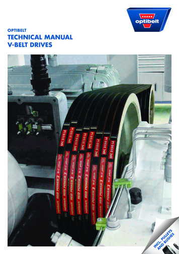
Body Tube4. MARK THE BODY B6-44This Fin Spacing Guide will space equally three or four finson all popular body tubes sold by Estes Industries. To spacethe fins, center the end of the tube in the circles, then mark atthe (4) lines for 3four fins or on the (3) lines for3three fins.Mark the body tube for fin alignment using the “V” notch of adrawer sill or door frame. Match the edge of the notch with aspacing mark; run a pencil along the edge to draw your guide4 the fins to the body on these lines will insure4 thatline. Gluingthey are straight.5Estes also manufactures a special Tube20 0 Marking Guide for5 and a Fin Alignmentmarking fin location lines on body tubes,5Guide that holds fins in proper alignment 5while0 gluing.Engine BlockGlueEngine CasingWhen mounting the engine in a model with an engine block,wrap the engine with masking tape until it makes a tight friction fit in the tube, then slide the engine into place. If the fit istoo loose, the engine will kick out at ejection and may notdeploy the recovery system. If the fit is too tight, you may damage the model trying to push the engine in place. Adjust theamount of tape as needed.If the arrangement of the engine mount tube and fins allowsenough space, a wrap of tape around the tube and engine jointcan help hold the engine in the model.67080345. INSTALL THE ENGINE MOUNTBe sure the glue on the engine mount rings is completely drybefore you install the mount in the body tube. The fin alignment lines should be drawn on the body before installing theengine mount. You will position the mount so the engine holder is midway between two fin lines for easier operation.Before gluing, make sure the mount slides easily in the bodytube. If it’s tight, sand it until it slides easily.Smear a liberal amount of glue around the inside of the bodyover the area where the mount’s ring or coupler will fit. Insertthe mount into position in one smooth motion. DON’T pause,or the glue will “grab” it in the wrong place! Support the tube“nose-up” while the glue dries.Engine HoldersIn many models a quick release engine holder (also called anengine hook) is the best device to use for mounting an engine.The forward end of the engine holder is inserted through a 1/8inch wide slit in the tube, and prevents forward movement ofthe engine. Apply glue fillets where the engine mount spacerrings attach to the engine mount tube for extra strength.To mount an engine in a model with an engine holder, springthe end of the holder up and slide the engine into place. Checkto make sure the end of the holder latches securely over theend of the engine.6. BALSA FINSFins are used to aerodynamically guide your rocket. Somemodel rockets use fins made from thin sheets of balsa wood. Inmany kits the fins are pre-cut for you by a punch die. In otherkits, or to make customfins, you must use a patdgeing Etern to mark and cut aLeadblank sheet of balsa. AlltionDirecbalsa fins must be cut soGrainthat the grain of thewood runs parallel withthe leading edge of theTrailing Edgefin for maximumstrength.2. SHOCK CORD MOUNTSGLGLUEUE12RoTipSpread Glue, Fold - Pinch & HoldSlit-N-Glue Methodot EdgeAttach the shock cord securely. Both methods shown yieldgood results. The slit-n-glue method is good for body tubes toosmall for an anchor mount.The anchor is cut from paper or index card stock. Be sure toglue the anchor far enough into the tube or it will interferewith the proper fit of the nose cone.33Die-Cut Balsa Fins1"Cut 2 Slits 1/2” Long1/4” ApartThread InApply GlueBefore removing the die-cut fins from their sheet, use extrafine sandpaper to sand both surfaces of the sheet of balsa (asanding block is helpful here). Use a modeling knife to carefully cut through the points where the fins are still attached to thedie-cut sheet, then remove the fins. Stack the fins together andsand all edges square.YESAnchor MethodSanding Block3. SECURING A SCREW EYEIf your model uses a screw eye to attach the shock cord to abalsa nose cone or adapter, make sure the screw eye is securely attached. Make a hole by inserting and removing the eye;then squirt glue into the hole and replace the eye.2SandpaperDie-CutBalsa SheetRemove UsingModeling KnifeSandpaperFins StackedTogether
Balsa Fins From PatternsSometime after the fin joints have dried completely, theyshould be reinforced. Do this by applying a “fillet” of glue asshown. Always support the body in a horizontal position whilefillets are drying so that the glueFilletsdoes not run. Build up the filletsin several thin layers, allowingeach layer to dry between applications (this is much faster thanwaiting for a single thick filletlayer to dry).To make fins from an un-cut sheet of balsa, start with a fullsize fin pattern cut from stiff paper or thin cardboard. Whenlaying out the fins on the sheet of balsa be sure to position thepattern so that the leading edge of the fin runs parallel to thegrain direction! Trace around the pattern with a pencil or ballpoint pen to mark the balsa for each fin.LeaGra d EdgeinFinFINgePatternPATTERNt EdRoo8. ATTACHING LAUNCH LUGSLayoutThe launch lugs are used to position the rocket on the launchrod. The lugs and rod help guide the rocket in its first few feetof flight. The model must be guided until it is going fast enoughfor the fins to guide it. Launch lugs are attached in much thesame way as fins. If a stand-off is used to keep the rod from hitting a large diameter payload section, attach the lug to thestand-off piece first, then attach the unit to the body. Sightalong the tube to beGluesure the lug is parallel to the body tubebefore the glue sets.Apply glue fillets toPlainthe lug after the initial glue joint hasW/Stand-Offdried.LAYOUTTracingTRACINGUse a metal straightedge whenever possible. Hold the knifeblade at a 90 angle to surface being cut, and handle at about45 for clean cut. If blade is dull or held too high, balsa tends totear. A razor saw blade may be required to cut thicker balsa.9. PARACHUTE ASSEMBLYThe most common model rocket recovery system is the parachute. On page 9 you will find alternate recovery systems. Toassemble an Estes parachute, cut out the plastic parachutealong the dotted lines. Apply the six vinyl tape rings to the corners of the parachute and punch holes through the parachutematerial in the center of the tape rings using a sharp pencil.Cut three equal length shroud lines that are twice as long asthe parachute diameter. Tie both ends of the shroud linesthrough the holes in the tape rings, as shown.Shaping Balsa FinsThe instruction sheets in many kits tell you to sand all edgesof the fins square. This is fine, and it is the easiest method, butyou can reduce drag and increase the altitude performance ofyour rocket by proper shaping of the fin edges.For general purposes, sand all fin edges round except theroot edge (the edge that glues to the body). Make the rootedges straight and square, never rounded! The sides of the finsshould be sanded smooth.On high performance models sand the fins to the streamlinedshape shown for minimum drag. The front (leading) edge ofthe fin should be rounded; the back (trailing) edge should cometo a sharp edge.Rounded EdgesTo attach the parachute to the nose cone or adapter eyelet,thread the shroud lines through the eyelet, pass the parachutethrough the loop of shroud lines as shown, then pull the linestight.StreamlinedIn addition to regular, pre-printed model rocket parachutes,you can assemble custom parachutes using a wide variety ofthin plastic sheeting. When making a chute from scratch, cutthe plastic sheet to shape, then attach shroud lines as shownpreviously. Carpet thread makes excellent shroud lines.7. ATTACHING THE FINSAfter marking the tube and sanding the fins, you are ready toattach them to the body. The best way to attach balsa or fiberfins to a rocket with white glue is by using a “double glue joint”.Apply a layer of glue to the root edge of a fin and a thin layer ofglue to the body tube where the fin will be attached. Do thisfor all fins and allow this glue to dry. Then apply a second lineof glue to the root edge and press the fin in place onto thebody, holding it in place until the glue begins to set. Before theglue sets completely, sight down along the body tube to makesure that the fin is aligned parallel with the tube, and orientedstraight away from the surface of the tube. Adjust the fin alignment as needed. Support the rocket body in a vertical positionwhile the glue on the fins dries.Parachute ShapeThe most common parachute shapes are square, round,hexagonal and octagonal. While square parachutes are the easiest to make, they are not very efficient and allow a considerable amount of sway during descent. Round parachutes arevery stable in descent, but are more difficult to make.Hexagonal and octagonal parachutes are stable and reasonablyeasy to make. The accompanying drawings illustrate methodsfor making these shapes.GlueFin DryingPosition3
Snap Swivel AssemblyTape Strips OrTape Inside OfPayload SectionTape Strips OnInside Of PayloadSectionIt’s often worthwhile to attach your parachute to a snap swivel to allow the ‘chute to be easily removed. This lets youchange parachute size in response to different wind conditions,or swap ‘chutes between models. A snap swivel has an eyeleton one end and a wire snap hook on the other. The swivel connection in between helps keep your parachute lines from tangling up if the ‘chute rotates on descent. Snap swivels areavailable from Estes or where fishing supplies are sold.GlueGlue10. CONNECT IT TOGETHERFINISHINGThe first illustration shows how nose cone, parachute androcket are connected on most models. If the rocket has aheavy payload section, it’s a good idea to use two chutes asshown in the second picture.The finish of a rocket starts with the very first steps of assembly. Sloppy gluing and other messy habits will ruin the appearance of a rocket so that nothing can be done to get the perfectappearance which is desired. On the other hand, careful construction will make a model look good even before the paint isapplied. A model with a smooth finish not only looks more professional, it expeiences less drag in flight, so it flies higher.The degree of difficulty in finishing a model rocket dependson the materials used in its construction. Models with plasticnose cones and fins are the easiest to finish (some come withall pre-colored parts and require no finishing at all). Modelsbuilt with balsa parts require extra steps to produce a smooth,shiny finish.11. CUTTING TUBES1. SANDING AND SEALING BALSA PARTSWhen building custom design rockets or replacing damagedtubes on your models, you will often need to cut a specificlength body tube. Here’s how to get a neat cut every time.To get a smooth finish, the wood grain of the balsa must befilled. Many suitable types of sanding sealers and wood fillersare available at hobby shops and hardware stores. Many sanding sealers give off harmful fumes and must be used only inwell-ventilated areas. Water-based wood fillers have no noxious fumes; you may need to add water to thin them to a brushable consistency.Paint cannot replace sandpaper. If a balsa surface is notsanded and sealed carefully, it will be impossible to get asmooth paint job. Begin by sanding all balsa surfaces withextra-fine sandpaper until smooth.(1) Mark the tube at the point where the cut is to be made.Wrap a straight strip of paper around the tube and align theedge with the mark. Draw a line completely around the tube.You can also use the pencil holder on the Estes Tube MarkingGuide to draw the line.Draw LineBalsa SandedBut UntreatedNext, apply a coat of sanding sealer to the balsa. Let this drycompletely, then sand with 320 grit (or finer) sandpaper, untilthe surface is smooth again. Apply more sealer, repeating theprocedure until all the pores in the balsa are filled.(2) Slide a stage coupler or expended engine casing into thetube — center it under the cut position to support the tube.1st, Coat Sanded SurfaceNote Grain Depression(3) Using a sharp blade, cut lightly along the line, rotatingthe tube as you cut. Don’t try to cut all the way through on thefirst turn. Use a light pressure on the knife for several turnsuntil you cut through.Practically all of the sealer should be sanded off after eachcoat. This is because the purpose of the sealer is to fill in theholes, not the smooth areas of the balsa.Apply LightEven Pressure4 or 5 Turns OfTube Will Cut Clean2nd, Coat Again Sanded3rd, Coat Sanded'Till Surface Is SmoothSlight DepressionRemainsDepressions Are Filled2. SPRAY PAINTING THE MODEL(4) Slide the stage coupler into the cut end of the tube. Holdthe tube near the cut end and work it over a flat sheet of veryfine sandpaper, with a circular motion as shown, to removeburrs and rough edges.12. CLEAR PAYLOAD SECTIONSModels that have a clear plastic payload section present aspecial problem: White glue will not bond the plastic to a balsanose block. To overcome this, apply tape strips to the inside ofthe payload tube, then glue the balsa nose block to the tapestrips using white glue.4Using a good enamel spray paint is the easiest way for anovice to get a smooth, uniform finish on a model rocket.Other types of paints can be used, but be wary of mixing different types of paint on the same model; paint compatibility problems may cause the model’s finish to wrinkle or “craze”. If indoubt, test the compatibility of different paints on a piece ofscrap material. Paint fumes can be harmful; only paint outdoors or in a well-ventilated area.To hold the model during painting, make a “painting wand”by rolling a sheet of newspaper into a very long, narrow coneand inserting it into the rocket’s engine mount. An expendedengine casing glued onto a wooden dowel also makes a great
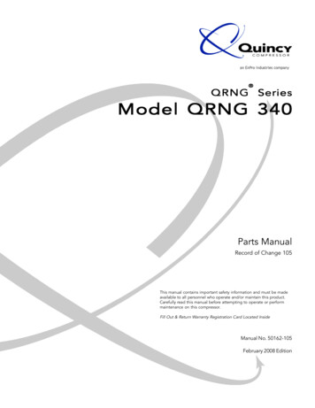
Dip DecalIn Waterpainting wand, especially for heavier models. Before painting,wipe the model with a clean, slightly damp cloth to remove anydust from its surface.Slide Decal FromThe Backing Sheet3. PRIMER COAT (Optional)While not necessary, a coat of sandable primer provides auniform base color and a better bonding surface for the paintlayers; it also helps fill any remaining minor surface imperfections. Spray on the primer in thin coats until the model is auniform color. When the primer is completely dry, lightly sandthe surface with 400 grit (or finer) sandpaper.Blot AwayExcess WaterAfter the decals have dried completely, spray the model withclear acrylic coating to protect the finish. Apply the clearspray in several thin coats, allowing time for each coat to dry.If the model was finished with fluorescent paint, apply a lightcoat of clear spray before applying decals.4. BASE COLORThe base color is the lightest of the colors to be used on themodel. Usually this will be white. If the model is to be paintedwith fluorescent colors, the base coat must be white.Always spray on the paint in light, even coats, allowing themodel to dry between each coat. Trying to cover the modelwith one thick coat of paint will only result in paint runs.Several thin coats will also dry faster than a single thick coat.When the first coat has dried completely, sand lightly withextremely fine sandpaper. Wipe off any dust and apply another coat. Let this dry, then follow with additional light coatsuntil the model has a clear, pure color.Let the base coat dry completely in a warm, dust-free area.Allow the model to dry a full day if it is to be masked for additional colors.Move CanParallel ToWork8” To 10”From Body5. THE SECOND COLORSTABILITYOne of the first things a model rocket designer learns is that avehicle will not fly unless it is aerodynamically stable. By stable we mean that it will tend to keep its nose pointed in thesame direction throughout its upward flight. Good aerodynamic stability will keep the rocket on a true flight path eventhough some force (such as an off-center engine) tries to turnthe model off course.If a model is not stable, it will constantly turn its nose awayfrom the intended flight path. As a result it will try to go allover the sky, but end up going “nowhere.” An unstable rocketwill usually tumble to earth after the engine burns out, damaging the model.When a free-flying objectrotates, it always rotatesaround its balance point. Theproper term for the balancepoint is the center of gravity,abbreviated as CG. Thus thebalance point (CG) is the pivotfor all forces trying to turn therocket.The most significant forces acting on a model rocket in flightare caused by the thrust of the engine, the action of air on thenose and the action of air on the fins. Off-center thrust andforces on the nose try to bring the nose of the rocket around tothe rear. They are opposed by the forces acting on the fins. Allthese forces are amplified by the distance from the location ofthe force to the center of gravity.Don’tForget TheEnds AndEdges“Sag” Or “Run”Results FromHolding Can TooClose To WorkWhen the base color has dried completely, cover all areas onthe model which are to remain this color. Cover small areaswith masking tape. Large areas should be covered with typingpaper, held down at the edges with masking tape. It’s important to seal the tape down tightly along the edge. Masking tapethat is too sticky may pull up the base color paint whenremoved; if you have this problem, you can stick the tape toyou skin before applying it to the model to remove some of itstackiness.Areas To ReceiveSecond ColorAreas To RemainOriginal ColorAs long as the forces on the fins of the rocket are greatenough to counteract the forces on the nose and any off-centerthrust, the rocket will fly straight. If the fins are too smalland/or too close to the center of gravity, there will not beenough force to counteract the force on the nose. As a result,the nose will swing out to the side and the model will try tochase itself around the sky.With the model masked, apply an additional thin coat of thefirst color to finish sealing the edges of the tape. When this isdry, apply the second color in several thin coats. Use justenough paint to get good color. After the last coat is dry,remove the masking carefully to avoid peeling the paint. Athird color would be applied in the same way as the second.Force On Left Side Can BeBalanced By 6. FINAL TOUCHESFor best results, let the paint dry overnight before applyingdecals. Some models have self adhesive decals; these must bepositioned very carefully before pressing into place, since theycan not be moved once they are stuck down.To apply a water-transferable decal, first cut it out of thedecal sheet, then soak it in lukewarm water for 60 seconds oruntil it begins to slide on the backing sheet. Slide the decal sothat one edge is off the backing. Position this edge on themodel and hold it in place while pulling the backing out fromunder. Smooth the decal down with a damp finger, then blotaway any excess water with a rag or paper towel.2oz52oz1oz Large Force Close By, OrSmall Force Far AwayThe side forces on the nose and fins of a rocket that is flyingstraight are very small. When something disturbs the rocketand it starts to rotate sideways, the side forces on both noseand fins increase. (There is some aerodynamic force on thebody; however, it is small and can usually be ignored.)Depending on the size and shape of the nose and fins and theirdistances to the center of gravity, one will overpower the otherand force the rocket to turn its way. If the nose overpowers thefins, it’s too bad. However, if the fins overpower the nose, therocket will swing back into line and continue on its way.
accord unless they are started straight. This is done by holdingthe rocket in one hand with the arm extended and then pivoting the entire body as the rocket is started in the circular path.It may take several attempts before a good start is achieved.If it is necessary to hold the rocket to start it, an additionaltest should be made to determine when the model is stableenough to fly. Move the loop back on the body until the tubepoints down at a 10 angle below the horizontal. Repeat theswing test. If the model will keep its nose pointed ahead oncestarted, it should be stable enough to launch.Although determining the exact relationships between various forces on a model rocket requires higher mathematics, certain practical rules can be used by even the beginning rocketmodeler to design stable rockets. The first rule is to use a longbody. Until you have considerable experience in designingmodels, the length of the body tube used should be at least 10times its diameter. This makes it easier to get enough distancebetween the center of gravity and the fins.The second rule is to make the fins large. The larger the fins,the more force they will produce when the rocket starts to turn.For the first few designs, use a fin which is at least as large asthe example in the illustration.Double Check A Rocket WithQuestionable Stability AsFollows:Move String Back UntilNose Of Rocket PointsTen Degrees Down Repeat TheSwing Test0 -5 -10 -15 Rocket Should Still "Fly"Nose Forward10dd2dd1-1/2dBe careful when swinging a rocket overhead: A collision witha nearby object or person could be serious. Always do yourtesting in an open, uncluttered area.Don’t try to fly a rocket that has not passed the test. Mostunstable rockets loop around in the air harmlessly. However, afew marginally unstable models will make a couple of loopsand then become stable due to a CG shift as the propellantburns. When this happens, the model can crash into theground at high speed.If your rocket does not pass the stability test, it can usuallybe made stable. Two methods can be used: The balance pointcan be moved forward, or the fin area can be enlarged. Tomove the balance point forward, add weight to the nose cone.For models with hollow plastic nose cones, pack some clay intothe tip of the nose. To add weight to balsa nose cones, attachwashers to the base of the cone. The CG can also be moved forward by adding a payload section to the model. Fins can eitherbe replaced with larger ones or extra tabs can be glued to therear or tip edges of the fins. Additional fins could also beadded to the model. Some scale models use supplementaryclear plastic fins. After making your changes, swing test themodel again to be sure it is now stable.Minimum Fin SizeExample:Rocket 12" Longd Body TubeDiameter1.5" Ahead Of FinsRocket Should Balance HereThe third rule is to place the fins as far back on the rocket aspossible. Generally, this means that the rear edge of the finwill meet the rear end of the body and the fin will be sweptback. Do not place any fins ahead of the center of gravity!Finally, the rocket should balance at least 1/8 its lengthahead of the front of the fins. This gives the fins the leveragethey will need to counteract the force on the nose.Remember that these rules are general; they are based onexperience rather than precise mathematical analysis. Alwaysremember to test your model for stability before you launch it.SWING TESTING FOR STABILITYThe easiest way to test the stability of a model is to fly it —without launching it. Do this by attaching
44 4 4 3 33 5 20 50 55 60 70 80 When mounting the engine in a model with an engine block, wrap t