Transcription
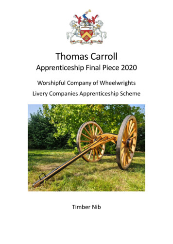
Thomas CarrollApprenticeship Final Piece 2020Worshipful Company of WheelwrightsLivery Companies Apprenticeship SchemeTimber Nib
Thomas Carroll September 2020IntroductionDuring my apprenticeship I gave lots of thought to what I wanted to make for my apprenticepiece. I had a few ideas such as a bicycle, a model tip cart, or a pair of wheels with differentconstruction and techniques.I chose to make a 1/3rd scale model of a large timber nib, I was intrigued by the size, utilityand overall shape of the nib and saw an opportunity to learn and add to the skills I have learntduring my apprenticeship whilst building it.My model is based on the large 8ft nib from the Knole Estate in Sevenoaks, Kent which residesat the Weald and Downland Museum in Singleton where it is currently on display.Before I became an apprentice wheelwright I worked as a forester. I was involved in movinglots of timber about and saw the ever-present drive to get more timber out of the woods forpurposes such as sawlogs and firewood. This was achieved with large machinery that left amark on the landscape once the work was finished.This drew me towards a timber nib as it is a simple yet graceful implement that moves timberout of the forest with horses or oxen.1
Thomas Carroll September 2020Contents pageIntroduction11 - History of the Nib3-42 - Research5-93 - Plans104 - Wheels11-205 – Axles and metalwork21-236 – Body wings and pole24-277 – Finish28-318 – Costing329 – Evaluation3310 – Bibliography34-362
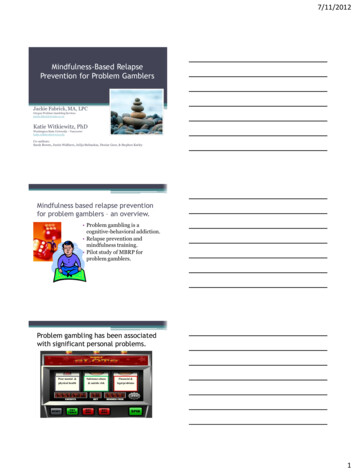
Thomas Carroll September 20201 - History of the NibA nib was used to move large heavy felled timberfrom the forest out to the roadside where it wouldbe loaded on to a timber wagon. The large wheelsaided in the straddling of larger saw logs and gavegood ground clearance to manoeuvre over therugged terrain of the forest.Some of the alternative names are Neb, Bob, Nibtogether with regional and national variations. Thesewould have alternative names such as a Jigger,Janker, Limber or Pair of wheels.A nib, together with suitable trained horses or oxen,would have enabled the most efficient method ofhauling a loaded nibThe nib on display at the Weald and DownlandMuseum in Singleton is quite large with 8ft wheelswhich would give ground clearance for a 4ft diameterlog when in use, anything larger than this would havehad a saw pit dug next to the timber and sawn in situ.Unlike a wagon that carries its load above the axle, anib lifts/drags the load below the axle on chainswhich creates a low center of gravity helping with stability over rough ground.The nib would have seen dwindling use in the forest and would have been a rare sight afterWorld War Two when tractors and machinery began to become more commonplace,although the nib could be used with a tractor or crawler which would have extended theusage period.The use of horses for timber extraction in sensitive areas of woodland is still a commonpractice today as it minimises the damage to the flora and fauna present in the woodland thatmodern day timber extraction equipment would otherwise damage or destroy.“The principle of loading was simple and ingenious. The neb was pushed back to the middleof the tree, straddling over it with one wheel on each side. There, its shafts being liftedtowards the sky, the riser atop of the axle lay back almost on the tree. So, a stout chainround the tree easily reached the riser and was hooked on to it. But when the skyward –pointing shafts were pulled down again for hauling, they brought the riser upright and thetree rose with it, clear off the ground. Two or three strong men could generally do this. Yousee, the length of the shafts gave good leverage.”(‘Sturt, George’ – The Wheelwrights Shop – pages 189 to 190)3
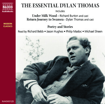
Thomas Carroll September 2020Four horse log limber moving a mature beech log in Eawy Forest, Normandy 1918.There is a YouTube video of a nib being loaded. This is a great example of a nib being loadedand used with a Belgian draft horse.https://www.youtube.com/watch?v gWRscujkPxU&t 17sThe Strongest Horse by Robert Piessens.4
Thomas Carroll September 20202 – ResearchWhilst carrying out research, Iviewed several nibs at the Wealdand Downland Museum and theRural Life Museum.There were variations in theconstruction and robustness ofeach, with the wheel size andconstruction dictating the type andsize of timber that could be moved.I noted that all the woodwork on thenibs were well strapped in ironworkfor protection. This was done tostrengthen key areas, as it is likelythe design would have beenimproved on over many yearsfollowing breakages and damageduring use.Researching the large timber nib January 2020I was fortunate to come acrossseveral detailed drawings ofdifferent nibs by John Thompsonwhich were supplied to me by theGuild of Model Wheelwrights.Amazingly, these plans (datedNovember 1974) included the verysame large nib I had already decidedto base my model on at the Wealdand Downland Museum.When I visited the Museum andtook my own measurements, it wasinteresting to note the differences in the actual measurements and the design measurementswhich could be down to repairs, decay and decline in the condition in 46 years. It would beunable to lift a log in its current condition as it is has seen better days, with the pole and wingsbeing held together with a ratchet strap and the wheels have started to fall apart.5
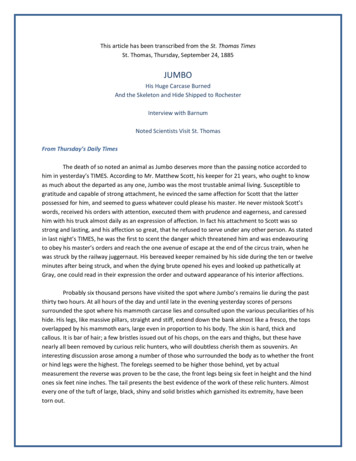
Thomas Carroll September 2020In America, timber nibs are known as High Wheels and were popularised in 1875.Commercially made by the Overpack Company in Michigan, which shipped the wheels all overthe United States and Canada. These wheels commonly came up to 10ft which was requiredto cope with the large old growth timbers.Logging was usually a winter job where the snow and ice would facilitate easy skidding andtransport of timbers to the riverbanks to await the spring log drive. In the summer Michiganbig wheels became popular and were utilised to make logging possible in all four seasons. Thismade the movement of logs possible without the need for ice and frozen ground conditions.Whilst carrying out my research I came across several internet websites and videos onYouTube.The French have several variations ofthe Nib called a Diable (Devil) orTriqueballe as they were known.“Transport of large pieces of wood:the devil.The devil is essentially composed oftwo wheels similar to the wheels ofan ordinary cart, but generallyhigher (up to 2.50 m in diameter),joined by a hell axle, bent, andcovered with a strong piece of woodwhich hugs the shape of thehanger.”“The hand truck can be pulleddirectly by cattle: oxen or mules. Butthis process can be dangerous in thetransport of long pieces whichsometimes strike the hocks ofanimals. Most often, the hand truckis towed behind a tractor, or evenbehind a cart.”“The loaded hand truck should benoticeably balanced on its wheels,weighing slightly forward”(Taken from Véhicules agricoles desrégions de France).The picture to the right shows a similar nib to the one I have based my model on, with a bentaxle.6
Thomas Carroll September rink/trik09.jpgThis is a nib being used to skid timber from the forest, I like this photo because it is an originalnib still in use to this day. This also shows the manoeuvrability in a tight stand of 8d84abbe055f2e9b4f63b248890d.jpgI found many variations of nibs in the United States, where the design has been altered andimproved upon. The nib above shows the use of a substantial metal construction and thebenefits this brings in the size and weight of the timber it can transport.7
Thomas Carroll September /thumb/9/9c/Big Wheels with log.jpg/1280px-Big Wheels with log.jpgI chose to include this Michigan big wheel as it is an improvement on the original and morebasic design with the inclusions of metal rings on the inside of the spokes to help prevent andminimise damage to the back of the spokes during use.The axles were manufactured from hard maple and the pole of iron wood.8
Thomas Carroll September 4e6883301b7c821af36970b-piWashington State Historical Society, C1972.37.8, circa 1900The family climbing over the big wheel really emphasis the scale required to move largetimbers, the wheels are of a very heavy construction, you can see visible damage to thefelloes from use and a repaired felloe on the right eballe.jpgThe detailed plan above is of a Triqueballe (March 1924). I like this as it shows the finerdetails and construction.9
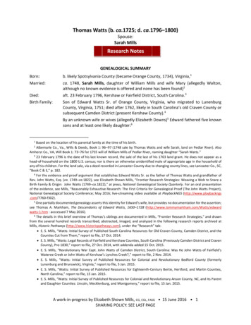
Thomas Carroll September 20203 - PlansTo start my piece off, I made a full-size drawing on a sheet of plywood to 1/3rd scale. I useda combination of the measurements taken from the display nib and the plans supplied to mefrom the model wheelwrights.I made the model to a 1/3rd scale as closely as possible, but had to make a few alterations tomatch commonly available steel section sizes for the strapping.The full-size drawing allowed me to get a good feel for the design and how everything wenttogether. It also gave me the opportunity to tweak a few things like the curves on the polewings because they looked too chunky and out of proportion to the scale.The drawing enabled me to make a few full-size patterns/templates out from thin sheets ofMDF. These were especially handy when getting parts out of rough boards, as I could see howthe grain would flow through the piece.Above is the scaled drawing on plywood.10
Thomas Carroll September 20204 - WheelsI started the project off with the wheels as these were the part I was most confident on.The wheels have 16 spokes each which meant I had to be mindful as there are quite a fewmortices in a small hub. This can take quite a bit of material out and I did not want to adverselyweaken the hubs.I made the wheels in the usual manner with traditional English timbers which included: Elm for the hub with its interlocking grain which resists splitting. This is a necessitywith the mortices for the spokes and the hole for the box.Oak for strength and stiffness in the spokes.Felloes from ash due to its flexibility and ability to absorb shock.The picture above shows two hub blanks and the spokes, all roughed to size.The hubs were turned on the lathe to shape with landsfor the tapered bonds. (see picture to the left) I boredthe hubs so that the box was tight in the front but loosein the back. This would give me some adjustment towedge the box in true once the wheels are tyred.I enjoyed turning the hubs as the elm turned nicelyeven though it has a rough grain but gave a good finish.11
Thomas Carroll September 2020The mortices were drilled out using the drill press with the dividing head to get an evenspacing for the 16 spokes. I followed this up with the morticer to cut the sides and backs ofthe mortices square.I carefully selected the oak for the spokes so therewere minimal defects, with the grain running as trueto the spokes as possible with minimal runout.The spokes were shaved up by hand using a drawknifeand spokeshave. The spokes on the original nib do nothave a lot of shape to them, this keeps them as strongas possible.A nib was a utility implement to transport timber sothere is little to no added embellishments, everythingserved a purpose without unnecessary detailing andrefinement.I secured the hub in the wheel pit and used the whalebone gauge to check I was cutting the fronts of themortice to the correct angle. This is done to achievethe desired dish on the wheel and is important as itadds strength.The spokes were driven in good and tight into thehub using the gauge to check their alignment.12
Thomas Carroll September 2020Once I had a wheel of stock and spokes, I used thedrill press to cut the tangs which makes a nice jobbecause it cuts the shoulders against a stop, toensure they are all consistent and round.The felloes were cut out of ash with attentionbeing paid to get the minimum amount of shortgrain at the ends. The dressings were applied byhand with a drawknife and spokeshave to give aclean sweep in and out of the dressing. I wasfortunate to be able to get the felloes out ofoffcuts from large felloes which makes good use ofthe timber.The photo above shows the tangs cut with a pattern for cutting the felloes from hardboard.13
Thomas Carroll September 2020Top left – ash offcuts from large felloes thismakes a good use of the timber and minimiseswaste.Top right – using a compass plane to clean thebelly of the felloe to remove any saw marksfrom the bandsaw.Bottom left – placing felloes around thewheel to gauge length and the locations of themortices for the tangs.14
Thomas Carroll September 2020The felloes above have been drilled for the mortices and had metal dowels inserted in theends for alignment.The knocking on of the felloes to the wheel. This is always a good stage (for me) as you cansee the wheel starting to take shape for the first time.15
Thomas Carroll September 2020Dressing the felloes with a hand plane to fit the tyre.Finished wheel ready for the tyre.16
Thomas Carroll September 2020I rolled mild steel bar for the tyres in the bender using the felloe pattern as a guide whenrolling to check the progress.I measured the wheels using a traveller and cut and shut the tyres so that they were 5/8thstight, which would give me a satisfactory amount of nip and bring all the joints together tight.17
Thomas Carroll September 2020I always enjoy the stage of putting the tyres on. It is always satisfying to see the wheel cometogether. I am always a little nervous at this point, as you do not want to see your work burnand char unduly.18
Thomas Carroll September 2020Once the tyres were on, I made the tapered bonds. I calculated the curve I had to bend thesteel on edge to. This was done by using an online tapered cone calculator. I then rolled themround so I would get the taper required to match the hubs. When rolling the steel round, Ichecked frequently against the hub to measure my progress.This worked well although it took some adjustment to get a consistent angle on the bondsso that they would fit well.19
Thomas Carroll September 2020Using the press to get the bonds on tight, I had to use a metal ring of the correct internaldiameter to apply the force on the bonds without the hub getting in the way.I did this so I did not have any charring around the hubs. This would have shown through theoil finish if I had put them on hot. I chose small 3mm thick steel to match the scale, this wouldnot have expanded a great deal when heated.20
Thomas Carroll September 20205 - Axles and metalworkDouglas Andrews kindly let me use an old hand cart axle andboxes that were lying about the workshop. These were not aperfect fit for the scale I was working to because, they wereslightly too large. Once I had made some minor adjustmentse.g. turning off the oil well from the back of the box and thematching part on the axle they worked well as they wouldhave been too large to be recessed into the riser.The axle was too long for my hub in its original condition,which would have stuck out of the front of the hub. I couldhave changed the scale and made a larger hub to incorporatethe axle size, but I instead chose to cut the axle just behindthe lynch pin slot and shorten it to the required amount andweld it back together.I ground a bevel on both pieces of the axle that were to bewelded back together. I used a welding rod to reach thebottom of the joint to achieved a fully penetrated weld joint.As I cut the axle at the back of the lynch pin slot, I had to remove some material from therear of the pins, so that they would fit nicely.My original plan was to have a one-piece continuous axle using the old hand cart axle. Themore I thought about this and in practice, I found it difficult to bend the axle to the tightcurve in the riser.I made two axle arms by forging down the axle until I had a straight arm that tapered. I thenbent the axle arms to fit the curve in the riser, before adding the dip in the axle. This wasdone so that the bottom spoke would be plum and I checked the drawing to make sure mywork was accurate.The axles were one of the hardest challenges for me during the project. I learnt a lot aboutgetting steel to the required temperatures. This was especially important with the wroughtiron as I was looking to achieve quite a curve in the arm to match the riser.Bending the curve took me a couple of attempts to get the required shape I was after. Themistake I made, was not getting the workpiece hot enough before bending. Thissubsequently produced a few small cracks in the wrought iron.I cleaned these cracks out with an angle grinder and welded them up, which stopped thecracks propagating and getting worse.21
Thomas Carroll September 2020The cracking only happened on the first half arm. The second half arm I successfully got thematerial to the correct forging temperature, which is a bright yellow and is around (1150Celsius). At this temperature, the wrought iron is more malleable and will bend well. If themetal gets closer to white hot it can begin to burn the material.The picture above shows the axle being welded back together to the correct length for thescale.The rest of the metalwork including (the strapping, axle clips, chain loops and the plates onthe top and bottom of the riser) were straightforward. I used the drawing to guide me onsizing and shape for the reaming metalwork.I chamfered all the metalwork over the anvil to remove the rolled edge that comes on mildsteel bar. If I had left the rolled edge on, it would have made the pieces look unfinished.I created a few patterns to check the shape of the iron work. I used these pattern pieces tooffer up to the workpiece to check the fit. I did this because I did not want to use the finalwoodwork as this could have left marks or damaged the surface which would have shownthrough the final oil finish.22
Thomas Carroll September 2020The bolts that go through the riser and sandwich the bottom and top plates together, weremade by threading a nut onto an appropriately sized steel bar. I then used the tig welder toweld the space on top of the bolt to create a flush head. (Middle photo)The above right picture showsthe axle clips, these were drilledwith holes before for fixing.The picture to the left showsround bar chain loops that arethreaded on the end to enablefixing into the riser. I used the tigwelder to weld on square nuts tothe shafts to act as collars to stopthem pulling into the riser whenattached.After the metal was sandblastedthe etch primer was applied andthen was followed by blacktopcoat. This was applied to allmetalwork prior to assembly.23
Thomas Carroll September 20206 - Body Wings and PoleI found a well-suited piece of oak in the workshop for the riser and wings with suitable curvedgrain to minimise any short grain and run out through the pieces.I required a final thickness of 3 inches for the riser, so I had to get this out of a thicker plank.The only issue being the moisture content was around 16/18% when measured (as it was airdried). According to the records, it had been in stick for about four years. Therefore, at 1inchper year plus a year, it should be ready for use.I cut an oversized piece for the riser on the bandsaw and let this sit in the workshop for amonth or two. Because the workshop is a dryer environment, this would bring the moisturecontent down. After about 6 weeks the moisture content dropped to around 14% which Ichecked with a (moisture meter). Ideally, I was after 12% but 14% was workable. The moisturecontent of the timber only becomes a concern if the piece is stored in a location where itcould dry out too quickly, which can then lead to shrinkage and cracking.The picture above shows patterns made from the original plywood drawing. I used paper totrace them off as I did not want to cut the plywood drawing up.I selected the grain carefully on the wings as Iwanted it to flow with minimal short grain and runout. I did this to ensure the wings were as strong aspossible.24
Thomas Carroll September 2020I made the riser, wings and pole out of oak for strength. These were all cut out to patternand finished off with hand tools to finalise the shape. I did this to remove the bandsawmarks that were present.The underside of the riser was notched out so that the axles would fit securely and in thecorrect place. The half arms were held in with axle clips and bolts.The riser is strapped at the top and bottom with metal work using bolts that connect thetwo. These stop the riser from splitting when a log is attached. When the pole is pulleddown, this puts a large amount of force throughout the woodwork.The image above shows the recess/pocket for half the arms to fit into the riser.The photo above shows the half arms fitted into the riser.25
Thomas Carroll September 2020The photos above show the jointing methods.I used a through-mortice with tapered sides and tenons tosecurely attach the wings and pole to the riser. I did this sothat they would drive in tight. I draw bored these withsuitable oak pegs to hold everything in place.I offered up the metal work to the pole to check for fit andto mark for dressings. This is so that the metalwork will sitnicely on the timbers and not interfere with any of thedressings.26
Thomas Carroll September 2020The picture above shows; assembling the riser, pole, and wings, a draw bore was used todraw everything tight.The photo to the left is an in-progress photo of themetalwork being attached to the body.27
Thomas Carroll September 20207 - FinishI had originally planned to paint the nib red asper the original. As the build progressed, Iincreasingly preferred the look of the naturaltimber. I thought an oil-based finish wouldenhance and bring out the natural beauty in thewoods.All the woodwork was sanded with 60 and 120grit sandpaper to remove any tool marks andrefine the surface ready for the finishing withthe oil.I used two coats of Danish oil on the woodworkto provide some protection and enhance thelook of the timber. I could have chosen manydifferent oils (linseed, teak, tung) but Danish oilprovides a subtle low sheen, which I think looksgood for this piece and matched with the blackmetalwork.I sandblasted all the metalwork to remove anyscale and rust that were present. I did this togive a good surface for the etch primer andsubsequent two coats of black paint to adhereto.Where possible, I painted the metalwork beforefinal fixing to avoid the possibility of gettingpaint on the timber. This would have shownthrough the oil finish and distracted from theoverall look.Once the nib was assembled, I went back over and primed and painted any of the fixings thatcould not be pre-finished as assembly would have chipped the paint off.28
Thomas Carroll September 2020The photo above shows the Danish oil finish which highlights the grain on the ash, oak, andelm beautifully.29
Thomas Carroll September 2020The photo above shows the metalwork riser and the dish in the wheels. This also shows thepole is trueThe photo above shows the metalwork, bonds, half arms and axle clips.30
Thomas Carroll September 2020The above photo shows a top view of the strapping on the pole and wings.The photo to the left shows the rearview including the chain with a hook onone end and an eye on the other toattach logs to the nib.31
Thomas Carroll September 20208 – CostingComing to a finished cost on the nib was difficult as this was my apprentice piece. I learnt alot whilst building it and producing a quality piece was my priority over speed.MaterialsMaterialOak for the spokes andbody of the nib.Cost per unit 50 per cubic footUnits used2.5Overall cost 125Ash for the felloes 30 per cubic foot1.25 37.50 10 each2 20--------Elm hub blanksSteel for metalwork andtyresSundries bolts, screws etcPaintDanish oil 40 15 10 10Overall cost of materials 257.50Labour costsThe nib took me 90 hours to complete and at an hourly rate of 20Cost of labour 1,800Workshop costs at 50 a day90 hours equates to 11.25 working days at 8 hours a day11.25 days at 50 562.50Overall costMaterials – 257.50Workshop charge – 562.50Labour – 1,800Total – 2,62032
Thomas Carroll September 20209 - EvaluationMy final piece has been an excellent test of my skills learnt throughout my apprenticeship.This project has enabled me to learn new techniques and work through problems andchallenges as they arose during the build. I found working on the axle the most challengingpart of the project as I had not worked on an axle before.The project also gave me a good insight into planning and design aspects that are requiredwhen making a vehicle. When making a piece from plan, everything must come togetherexactly right to make a well-functioning and good-looking piece.When putting the nib together, I had to adjust a few pieces of the metalwork to get them tofit well and look right. This was especially important on the strapping as its fit on thewoodwork is visible.Whilst building the nib I learnt about planning a job and always thinking ahead to the nextphase or part of the build.I set out to make a scale model of the large Timber Nib at the Weald and Downland Museum.The photos in this write up show how I achieved this and the processes I went through.Overall, I thoroughly enjoyed the project and the challenges making the nib gave me. I amvery proud of the result.My thanks to Douglas Andrews Master Wheelwright for his support and teaching throughoutmy apprenticeship.I also wish to thank the Worshipful Company of Wheelwrights and Worshipful Company ofCoachmakers and Coach Harness Makers for making my apprenticeship possible.N.B - Due to Covid 19 and the restrictions in place I have shown the journey I went throughto build my nib in this write up.33
Thomas Carroll September 202010 - BibliographyBooksSturt, George. (1958) – The Wheelwrights Shop. Cambridge: University PressMaclean, Murray. (2004) - Farming and forestry on the western front 1915 – 1918. Ipswich:Old Pond Publishing.DocumentsVéhicules agricoles des régions de France.MINISTÈRE DE LA CULTURE ET DE LA FRANCOPHONIE MISSION DU PATRIMOINEETHNOLOGIQUE MUSÉE NATIONAL DES ARTS ET TRADITIONS POPULAIRES ASSOCIATIONFRANÇAISE DES MUSÉES D'AGRICULTURE 1994EDOUARD DE LAU BRIEJEAN-RENÉ age6.html Accessed 16/09/2020Timber nib rural life museum face/advanced/farming/farm power/farm power tractors.htmlTractors and farming. Accessed 02/09/2020https://books.google.co.uk/books?id T-QDAAAAMBAJ&pg PA66&redir esc y#v onepage&q&f false (pages 66-69)Michigan big wheels in popular mechanics magazine. Accessed 23/08/2020https://en.wikipedia.org/wiki/Michigan logging wheelsAmerican logging wheels. Accessed 23/08/202034
Thomas Carroll September ured Vehicle Out of the Woods.htmlLogging wheels. Accessed -2/test/Timber Janker. Accessed s/mhkfa04b.pdfLogging wheels. Michigan history for kids. Accessed 30/08/2020https://www.youtube.com/watch?v gWRscujkPxUTHE STRONGEST Draft Horse by Robert Piessens. Accessed 16/09/2020https://www.youtube.com/results?search query The British Horse LoggersYouTube videos of horse logging. Accessed amond-now/2016/03/logging-big-wheels.htmlAccessed 5513924e6883301b7c821af36970b-800wiLarge timber nib - Accessed 15/09/2020http://geo.msu.edu/extra/geogmich/big wheels.htmlMichigan big wheels – Accessed 17/09/2020https://www.youtube.com/watch?v QVxmLBUqX60Horse-logging in Herefordshire - Accessed 15/09/202035
Thomas Carroll September 2020Other interesting linkshttps://www.youtube.com/watch?v xjHwolfBmFsDan Sumner - Apprentice Horse Logger - British Horse Loggers Charitable Trust - Horses Ndf3qgA1ATrCuaZQRobert Piessens You tube36
3 - Plans To start my piece off, I made a full-size drawing on a sheet of plywood to 1/3rd scale. I used a combination of the measurements taken from the display nib and the plans supplied to me from the model wheelwrights. I made the model to a 1/3rd scale as