Transcription
Subject code : CE 2303Name of the subject : RAILWAYS, AIRPORTSAND HARBOUR ENGINEERINGDate of deliverance :VSA Educational and Charitable Trust’s Group ofInstitutions, Salem – 636 010Department of Civil EngineeringChapterReference details :Airport Engineeringby RangwalaUNIT-3AIRPORT PLANNING AND DESIGNAirport Planning Airport planning requires more intensive study an9 fore thought as compared toplanning of other modes of transport. This is because aviation is the most dynamic industry and its forecast is quitecomplex. Unlike rail, road and water transportation, air transportation has yet not reached asteady state in design. it is very difficult to predict for the airport.Airport Master Plan Airport master plan refers the planner’s idealized concept of the form andstructure of the ultimate development of the airport. This plan is not simply the physical from of ultimate development but adescription of the st Master planning can apply to the construction of new airports as well as tosignificant expansion of existing facilities.The objectives of the master plan according to FAA are: To provide an effective graphical presentation of the ultimate development of theairport are of the anticipated land uses adjacent to the airport. To establish a schedule of priorities and phasing for the various improvementsproposed in the plan. To present the pertinent back-up information and data which were essential to thedevelopment of the master plan. To describe the various concepts and alternatives which were considered in theestablishment of the proposed plan.Planning of a new airport:Step 1 The most important item in a airport planning is to estimate the future volume ofair traffic. Peak hoar volumes of passenger cargo and mail are required for proper allocationof space in the terminal building and for determining the size of the building.Peak hour aircraft movements assist in the design of runways, taxi and loadingaprons.Prepared by Mr.R.YUVARAJA, Assistant Professor / CivilPage 1
Subject code : CE 2303Name of the subject : RAILWAYS, AIRPORTSAND HARBOUR ENGINEERINGDate of deliverance :VSA Educational and Charitable Trust’s Group ofInstitutions, Salem – 636 010Department of Civil EngineeringChapterReference details :Airport Engineeringby RangwalaFollowing data is collected for the traffic forecast Area to be served Origin and destination of the residents and non residents of the area Population growth in the area Economic character of the area Income level per capita Types of business activities and the labour employed Trends in existing local traffic Trends in national air traffic volume Population, growth and economic standards of adjacent areasPrepared by Mr.R.YUVARAJA, Assistant Professor / CivilPage 2
Subject code : CE 2303Name of the subject : RAILWAYS, AIRPORTSAND HARBOUR ENGINEERINGDate of deliverance : VSA Educational and Charitable Trust’s Group ofInstitutions, Salem – 636 010Department of Civil EngineeringChapterReference details :Airport Engineeringby RangwalaHaving collected the above data, the forecast of the traffic for some futureyears, say 15 years is carried out reviewing past trends of the local airtraffic and future anticipated trends of the national air traffic.It may be pointed out that the process employed in making the forecast ofair traffic is, however not a precise science.It requires considerable experience and judgment.Step 2Prepared by Mr.R.YUVARAJA, Assistant Professor / CivilPage 3
Subject code : CE 2303Name of the subject : RAILWAYS, AIRPORTSAND HARBOUR ENGINEERINGDate of deliverance :VSA Educational and Charitable Trust’s Group ofInstitutions, Salem – 636 010Department of Civil EngineeringChapterReference details :Airport Engineeringby RangwalaThe next step is to ascertain whether the existing airport can handle the amountanticipated air traffic.Following points are considered in this respect Suitability of approaches for the type of airports. Capacity of runways and taxiways to handle the peak hour traffic (see chapter 7for airport capacity Adequacy of terminal building of handling 4 passengers and cargo. Adequacy of aprons and servicing facilities.Step 3 If the foregoing considerations prove that the existing airport is inadequate tohandle the anticipated traffic, the possible method for improving the capacity ofthe present airport should then be investigated.The improvement can be done in the following ways Runway extensions, new or parallel runway’ and high speed exit taxiways. Rearranging or increasing the size of terminal building and/or loading apron. Improving the traffic control devicesStep 4 Inspite of all the possible ways as listed above, if it is worked out that the presentairport cannot handle the air traffic, the designer thus arrives at the obviousanswer, i.e to propose a new airport.AIRPORT SITE SELECTION The selection of a suitable site for an airport depends upon the class of airportunder consideration.The factors listed below are for the selection of a suitable site for a major airportinstallation Regional plan Airport use Proximity to other airports Ground accessibility Topography Obstructions Visibility Wind Noise nuisance Grading, drainage and soil characteristics Future development Availability of utilities from town Economic considerationsAbove factors are briefly discussed as followsRegional Plan The site selected should fit well into the regional plan. there by forming it anintegral part of the national network of airport.Prepared by Mr.R.YUVARAJA, Assistant Professor / CivilPage 4
Subject code : CE 2303Name of the subject : RAILWAYS, AIRPORTSAND HARBOUR ENGINEERINGDate of deliverance :VSA Educational and Charitable Trust’s Group ofInstitutions, Salem – 636 010Department of Civil EngineeringChapterReference details :Airport Engineeringby RangwalaAirport Use The selection of site depends upon the use of an airport i.e. whether for civilian orfor military operations. Therefore, the airport site selected should he such that it provides naturalprotection to the area from air raids. This consideration is of prime importance for the airfields to be located in combatzones If the site provides thick bushes, the planes can be stored inside unnoticed.Sometimes the topography is such that the planes can be hidden by theunderground installations.Proximity to Other Airports The site should be selected at a considerable distance from the existing airports sothat the aircraft landing in one airport does not interfere with the movement ofaircraft at other airport. The required separation between the airports mainly depends upon the volume ofair traffic, the type of aircraft and the air traffic control, i e. whether the airportsare equipped with instrumental landing facilities or not.The following minimum spacing have been suggested as a guide for planning For airports serving small general aviation aircrafts under VFR conditions 3 2 km (2 miles) For airports serving bigger aircrafts, say two piston engine, under VFR conditions64 km (4 miles) For airports operating piston engine aircrafts under IFR conditions — 25.6 km (16miles) For aircrafts operating jet engine aircrafts under IFR conditions — 160 km (100miles)Ground Accessibility The site should be so selected that it is readily accessible to the users. The airline passenger is more concerned with his door.to.door time rather than theactual time in air travel The time to reach the airport is, therefore, an important consideration specially forshort-haul operations. The time required to reach an airport in a passenger car, from the business or residential centre, should normally not exceed 30 minutes. The best location is a site adjacent to the main highway. This provides a quickaccess and minimizes the cost of an entrance road. Availability of public transportation facilities, e.g., bus, taxi dc, further qualifiesthe suitability of the site and may also improve the business potentiality at theairport.Prepared by Mr.R.YUVARAJA, Assistant Professor / CivilPage 5
Subject code : CE 2303Name of the subject : RAILWAYS, AIRPORTSAND HARBOUR ENGINEERINGDate of deliverance :VSA Educational and Charitable Trust’s Group ofInstitutions, Salem – 636 010Department of Civil EngineeringChapterReference details :Airport Engineeringby RangwalaTopography This includes natural features like ground contours, trees; streams etc. A raised ground e.g. a bill top, is usually considered to be an ideal site for anairport.The reasons are: Less obstruction in approach zones and turning zones Natural drainage, low land may result in flooding More uniform wind Better visibility due to less fogObstructions When aircraft is landing or taking off, it loses or gains altitude very slowly ascompared to the forward speed. For this reason, long clearance areas are provided on either side of runway knownas approach areas over which the aircraft can safely gain or lose altitude. The areas should be kept free of obstructions. The obstructions may consist of fences, trees, pole lines, building and othernatural or man made objects. Sometimes the ground itself may slope upwards from the end of the runways tosuch an extent that it forms an obstruction to the aircraft operation. If obstructionexists around a site over which an airport is to be built, the removal is imperativeat any cost.Visibility Poor visibility lowers the traffic capacity of the airport. The site selectedshould therefore be -free from visibility reducing conditions, such as fog,smoke and haze. Fog generally settles in the area where wind blow is minimum, e.g. in avalley, Smoke and haze nuisance exist at sites nearer to the industrialareas. Therefore, trend of the future development of industrial area should alsobe studied and the site should be selected accordingly.Noise Nuisance The extent of noise nuisance depends upon the limb-out path of aircraft, type ofengine propulsion nd the gross weight or aircraft. The problem becomes more acute with jet engine aircrafts. Therefore, the site shoulu be so selected that the landing and take off paths of theaircraft pass over the land which is free from residential or industrialdevelopment. Sometimes buffer zone may have to be provided between the tike off end of arunway and a nearby residential area. If buffer zone cannot be provided, some acoustical barrier may have to beinstalled.Prepared by Mr.R.YUVARAJA, Assistant Professor / CivilPage 6
Subject code : CE 2303Name of the subject : RAILWAYS, AIRPORTSAND HARBOUR ENGINEERINGDate of deliverance :VSA Educational and Charitable Trust’s Group ofInstitutions, Salem – 636 010Department of Civil EngineeringChapterReference details :Airport Engineeringby RangwalaSURVEYS FOR SITE SELECTIONTraffic surveyTo determine the amount of air traffic including the anticipated traffic for future.Meteorological survey:To determine direction, duration and intensity of wind, rainfall, fog, temperature andbarometric pressure etcTopographical survey To prepare contour map showing other natural features such as trees, streams etc. To prepare a map showing such constructed objects aspole lines, building, roadsetc.These maps will be helpful in the jobs of clearing, grading and drainage.Soil survey To determine soil type and ground water table. This assists in the design of runway, taxiway, terminal building and the drainagesystem.Drainage survey To determine the quantity of storm water for drainage. This can be obtained fromthe rainfall intensity and the contour maps To locate possible outlets for drain water in the vicinity of he site. To study the possibility of intercepting or diverting the natural streams of nallasflowing towards the site under consideration.Material survey To ascertain the availability of suitable construction materials at a reasonable costand the mode of transportation of these materials to the site.ground contours and the cross-sections and longitudinal profilesZONING LAWS The permissible height of structures depends upon the airport and the aircrafttypes which would use the airport. The use of land for manufacture of certain items which may result in smokePrepared by Mr.R.YUVARAJA, Assistant Professor / CivilPage 7
Subject code : CE 2303Name of the subject : RAILWAYS, AIRPORTSAND HARBOUR ENGINEERINGDate of deliverance :VSA Educational and Charitable Trust’s Group ofInstitutions, Salem – 636 010Department of Civil EngineeringChapterReference details :Airport Engineeringby Rangwalanuisance, foul odour etc. is also controlled by the zoning laws; It should, however,be con that all zoning ordinances are reasonable and the application is fair;otherwise they are likely to create resentment from t public and may result inmass disobedience. Whenever it is felt that the zoning laws are provocative, sufficient compensationshould be announced in order to ascertain its effective implementation.APPROACH ZONE During landing, the glide path of an aircraft varies from a steep to fiat slope. Butduring take-off, the rate of climb of aircraft is limited by its wing loading andengine power. As such wide clearance areas, known as approach zones are required on eitherside of runway along the direction of landing and take-off of aircraft. Over this area, the aircraft can safety gain or loose altitude. The whole of this area has to be kept free of obstructions and as such zoning lawsare implemented in this area. The plan of approach zone is the same as that of the approach surface. , The onlydifference between the two is that while approach surface is an imaginary surface,the approach area indicates the actual ground area.Clear Zone The inner most portion of approach zone which is the most critical portion fromobstruction view-point is known as clear zone. Its configuration and dimensions are shown in FigureRUNWAY DESIGN Runway is usually oriented in the direction of prevailing winds. The head wind. i.e. the direction of wind opposite to the direction of landing andtake-off, provides greater lift on the wings of the aircraft when it is taking-off.Prepared by Mr.R.YUVARAJA, Assistant Professor / CivilPage 8
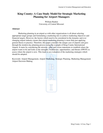
Subject code : CE 2303Name of the subject : RAILWAYS, AIRPORTSAND HARBOUR ENGINEERINGDate of deliverance :VSA Educational and Charitable Trust’s Group ofInstitutions, Salem – 636 010Department of Civil EngineeringChapterReference details :Airport Engineeringby Rangwala As such the aircraft rises above the ground much earlier and in a shorter length ofrunway. During landing, the head wind provides a braking effect and the aircraft comes toa stop in a smaller length of runway Landing and take-off operate if done alongthe wind direction, would require longer runway.Wind Rose The wind data, ie., direction, duration and intensity are graphically represented bya diagram called wind rose. The wind data should usually bi collected for a period of at least 5 years andpreferably of to years, so as to obtain in average data with sufficient accuracy. As far as possible, these observations should be taken at or near ‘site selected,since the wind conditions may vary considerably with location particularly inhilly regions.Wind rose diagrams can be plotted in two types as follows:Type I Showing direction and duration of windType 11: Showing direction, duration and intensity of windType I Wind Rose This type of wind rose is illustrated in Figure The radial lines indicate the wind direction and each circle represents the durationof wind. From the Table, it is observed that the total percentage of time in a year duringwhich the wind blows from north direction is 10.3 percent. ‘Ibis value is plottedalong the north direction in Similarly other values are also plotted along the respective directions, All plotted points are then jointed by straight lines as shown in Figure The best direction of runway is usually along the direction of the longest line onwind rose diagram. In Figure the best orientation of runway is thus along NS direction. If deviation of wind direction up to (22.5’ I 1.25’) from the direction of landingPrepared by Mr.R.YUVARAJA, Assistant Professor / CivilPage 9
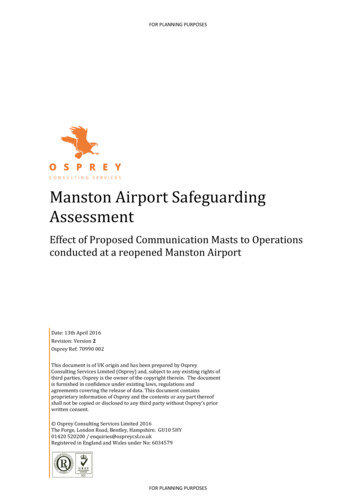
Subject code : CE 2303Name of the subject : RAILWAYS, AIRPORTSAND HARBOUR ENGINEERINGDate of deliverance :VSA Educational and Charitable Trust’s Group ofInstitutions, Salem – 636 010Department of Civil EngineeringChapterReference details :Airport Engineeringby Rangwalaand take-off is permissible, the percentage of time in a year during which therunway can safely be used for landing and take-off, will be obtained by summingthe percentages of time along NNW. N. NNE, SSE. S and SSW directions. This comes to 57.0 per cent. Calm period, i.e., the percentage of time duringwhich wind intensity is less than 6.4 kmph is also added to the above period. The total percentage of the time therefore comes to 57.0 13.5 705. This type ofwind rose does nut account for the effect of cross wind component.Type II Wind Rose This type wind data is used for of wind rose is illustrated in Figure The wind data as in the previous type. i.e. of Table 6.1 is used for this case. Each circle represents the wind intensity to some scale. The values entered in each segment represent the percentage of time in ayear during which the wind, having particular intensity, blows from therespective direction. The procedure for determining the orientation of runway is described below Draw three equi-spaced parallel lines on a transparent paper strip in such a waythat the distance between the two near by parallel lines is equal to the permissiblecross wind component. This distance is measured with the same scale with which the wind rose diagramis drawn. In Figure, the permissible cross wind component is 25 kmph. Place the transparent paper strip over the wind rose diagram in such a way that thecentral line passes through the centre of the diagram. With the centre of wind rose, rotate the tracing paper and place it in such aposition that the sum of all the values indicating the duration of wind, within thetwo outer parallel lines, is the maximum. The runway should be thus oriented along the direction indicated by the centralline. The wind coverage can be calculated by summing up all the percentages shownin segment. The percentage value is assumed to be equally distributed over the entire area ofthe segment.Prepared by Mr.R.YUVARAJA, Assistant Professor / CivilPage 10
Subject code : CE 2303Name of the subject : RAILWAYS, AIRPORTSAND HARBOUR ENGINEERINGDate of deliverance :VSA Educational and Charitable Trust’s Group ofInstitutions, Salem – 636 010Department of Civil EngineeringChapterReference details :Airport Engineeringby Rangwala When of the outer parallel lines of the transparent strip crosses a segment, afractional part of the percentage appearing in that segment within the outsidelines is also counted in the summation. Fractional areas are determined by judgment to the nearest decimal place. In Figure 6.3, the maximum wind coverage in per cent is obtained as (Calmperiod) 7.40 5.70 2.40 1.20 0.80 0.30 4.30 5.50*9.70 6.30 3.60.00 0.40-4-0.20 5.30 4.00 -f-2.70 2.l0 0.50 0.I0 0.03 2.lO 3.20 4.60 3.20 0.30 0.25 Read the bearing of the runway on the outer scale of wind rose where the centralline on the transparent paper crosses the angular scale. In Figure the best orientation of runway is along the direction whose whole circlebearing is zero degree i.e. along NS direction. If the coverage provided by a single runway is not sufficient, two or more numberof runways are planned in such a manner that the total coverage provided by themis as required.Correction for Gradient Steeper gradient results in greater consumption of energy and as such longerlength of runway is required to attain the desired ground speed. ICAO does notrecommend any specific correction for the gradient. FAA recommends that the runway length after having been corrected forelevation and temperature should be further increased at the rate of 20% for everyI per cent of effective gradient. Effective gradient is defined as the maximum difference in elevation between thehighest and lowest points of runway divided by the total length of runway.RUNWAY GEOMETRIC DESIGNRunway Length The basic runway lengths as recommended by ICAOfor different types of airportsare given in Table To obtain the actual length of runway, corrections for elevation, temperature andgradient are applied to the basic runway lengthRunway Width ICAO recommends the pavement width varying from 45 m (150 ft to 18 m (60 ft)for different types of airports. The typical transverse distribution of traffic on a runway is shown in Figure The figure indicates that the aircraft traffic is more concentrated in the central 24m (80 ft) width of the runway pavement. Another consideration in determining the runway width is that the outermostmachine of large jet aircraft using the airport should not extend off the pavementto the shoulders. This is because the shoulder is usually of loose soil or established soil etc. whichis likely to get into the engine and damage it;Prepared by Mr.R.YUVARAJA, Assistant Professor / CivilPage 11
Subject code : CE 2303Name of the subject : RAILWAYS, AIRPORTSAND HARBOUR ENGINEERINGDate of deliverance :VSA Educational and Charitable Trust’s Group ofInstitutions, Salem – 636 010Department of Civil EngineeringChapterReference details :Airport Engineeringby Rangwala The outer engines of a large jet transport are about 13.5 m (45 feet) from thelongitudinal axis of the aircraft. As such a pavement width of 45 m t provide adequate protection to the enginefrom the shoulder material during normal operations.TERMINAL AREA It is the portion of an airport other than the landing area. It serves as a focal point for activities on the airport. It includes terminal andoperational buildings, vehicle parking area aircraft service hangars etc. The terminal and operational buildings usually house all managerial andoperational activities for the aircrafts. Vehicular circulation and parking also require careful study, if congestion andinconvenience to the airport users have to be avoided. The airport entrance or ac road from a highway must be located in such a way thatit will avoid conflict with airport future development. Vehicle parking facilities should also be designed with a view to accommodatefuture expansion. The terminal apron is the loading and unloading area for passengers and cargo.Aircraft may also be fueled and parked here. At every airport provision of hangers for servicing and maintenance of aircrafts isplanned. The size of these facilities is determined by the expected type and volume ofairport activities.BUILDING AND BUILDING AREA The purpose of airport building is to provide shelter for various surface activitiesrelated to the air transportation. As such they are planned for the maximum efficiency, convenience and economy.The extent of the building area in relation to the landing area depends upon thepresent and future anticipated u of airport. Location of building area with respect to runway and taxiway should provideadequate space for future expansion of all structures.Building FunctionsThe various facilities provided in the airport buildings are as follows Passengers bud baggage handling counters for booking Baggage claim section Enquiry counter Space for handling and processing mail, express and light cargo Public telephone boothPrepared by Mr.R.YUVARAJA, Assistant Professor / CivilPage 12
Subject code : CE 2303Name of the subject : RAILWAYS, AIRPORTSAND HARBOUR ENGINEERINGDate of deliverance : VSA Educational and Charitable Trust’s Group ofInstitutions, Salem – 636 010Department of Civil EngineeringChapterReference details :Airport Engineeringby RangwalaWaiting hall for passengers and visitorsToilet facilitiesRestaurants and barsFirst aid roomGeneral store and gift shopsSpace for magazines, news display etc.Office space for airport staffWeather bureauPost office and banking facilitiesCustom controlPassport and health controlsControl towerSite Location The correct placement of the terminal building with respect. to the runways andloading aprons result in a more rational approach for the airport development. As the planning of runway proceeds, the requirements of building sites are alsokept constantly in view. The location of the runways are finalized with proper designation of adequatebuilding area. The suitability of an area, as a site for terminal building development, is evolvedin accordance with the following requirements Sufficient area for the first stage of building development with possibilityof future expansion Sufficient area for roadways Adequate area for car parking Layout of above items providing functional relationship with each other Convenient access of the main highway Central location with respect to runwayPrepared by Mr.R.YUVARAJA, Assistant Professor / CivilPage 13
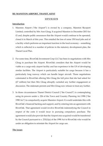
Subject code : CE 2303Name of the subject : RAILWAYS, AIRPORTSAND HARBOUR ENGINEERINGDate of deliverance :VSA Educational and Charitable Trust’s Group ofInstitutions, Salem – 636 010Department of Civil EngineeringChapterReference details :Airport Engineeringby RangwalaProximity and easy installation of utilities, e.g.telephone electricity, water,sewage, etc. papers, advertisementPlanning Considerations Two concepts are there for planning of the terminal buildings for a commercialairport, viz., centralization and decentralization. In the centralized plan, all passengers, baggage and cargo are funneled through acentral building and are then dispersed to the respective aircraft positions. In the decentralised plan, the passengers and baggage arrive at a point near thedeparting plane. All airline functions are carried out adjacent to the departing plane. The choice of a particular type of plan is governed by the space needed forparking of the aircrafts. When the aircraft parking area is located at an overall walking distance exceeding180 m. a change from the centralized system becomes necessary. Further, when the number of gate positions (loading area required for eachaircraft) required for the individual airliner at one airport exceeds thedecentralized plan also becomes operationally uneconomical. At this situation, another shift towards the ceatralization of each individual airlineOperation becomes essential. This results in a series of centralized airline spaces, arranged in a decentralizedpattern. The concept of an airport from the centralization to decentralization and finallydecentralization to centralization is illustrated in Figure In the past, passenger terminal facilities at almost all airport in the world havebeen in the form of a single central terminal building containing all the requiredfacilities and amenities. Prepared by Mr.R.YUVARAJA, Assistant Professor / CivilPage 14
Subject code : CE 2303Name of the subject : RAILWAYS, AIRPORTSAND HARBOUR ENGINEERINGDate of deliverance :VSA Educational and Charitable Trust’s Group ofInstitutions, Salem – 636 010Department of Civil EngineeringChapterReference details :Airport Engineeringby Rangwala This was satisfactor3i when the number of aeroplanes used and the gate positionsrequired were few; and when terminal building were relatively small andcentralizing all services are the cheapest convenient way of providing them. In the last 20 years, the air traffic has increased by many folds with the result thatthe centralized concept has become inoperative. The decentralized-centralized concept which is also known as Unit TerminalPrinciple is now becoming popular in the design of air terminals. There can be a number of variations of such a concept. For example the planner may exclude all or most of the amenities, such as thewaiting rooms, restaurants, shopping arcades and administrative offices etc.,which are used only by a minority of passengers who have to spend some time atairport while waiting to change planes or in case of long flight delays. Most passengers wish to move quickly and over the shortest possible distancefrom the kerb side to the gate position and vice-versa. The various amenities can be centralized separately in a building, devotedexclusively to them. It may be located close and connected with the operating units and may serve asingle Unit, or a group of them. The operating or handling units Would be purely functional with only suchessential amenities as book stall, money changer, flight insurance booths andtoilets. This concept of a separate building for amenities would lend itself conveniently tothe separation of domestic and international. The principle of a separate structure connected with the handling Units should beapplied wherever possible, leaving space for additional units to meet laterexpansion needs. The unit terminal principle fits in exceptionally well with the modern concept ofparallel runway patterns at large airports. Finally, the unit terminal concept automatically minimizes initial capitalexpenditure, while ensuring that addition can easily be made later, withoutrendering any of the previous expenditure as waste. The International Airport Committee, has recommended that full consideration begiven to the adoption of the unit terminal principle for the new terminal facilitiesto be constructed at the international airports in India.Vehicular Circulation and Parking Area Since the airport users normally active at the airport in automobiles, access roadsand parking facilities are of vital importance in the airport design The circulation of traffic and location of parking lots should be such that access tothe terminal building is as convenient as possible. Access roads are planned to provide fast connections between the airport and thecity. One of the present disadvantages of air travel is that the time saved the air travelPrepared by Mr.R.YUVARAJA,
Department of Civil Engineering Chapter Reference details : Name of the subject : RAILWAYS, AIRPORTS AND HARBOUR ENGINEERING Airport Engineering by Rangwala Date of deliverance : Prepared by Mr.R.YUVARAJA, Assistant Professor / Civil Page