Transcription
Shaft Seals & Oil Bath Seals
Our CommitmentOur commitment to the future of PEER is built on fulfilling your needs.Your satisfaction as a customer is the foundation of PEER and issupported by First class customer service On-time scheduled delivery Continuous product innovation Production tocustomizedspecifications In-depth inventory Technical andengineering support In-house andindependent testfacilities Strong complimentary bearing & chain products QS9000 / ISO/TS 16949 : 2002 certified manufacturing plants Superior quality in features and appearanceAll information in this catalog is subject to change without notice.
ContentsMaterial and specifications .2Fluid compatibility .3Metal case and spring specifications .3Storage and handling of shaft seals .4Shaft recommendations and tolerances .5Housing recommendations and tolerances .6Seal tolerances . 7, 8Lubrication .8Recommended installation methods . 9, 10Improper installation methods.11Standard seal designs .12Outer case and lip designations .13Lip, case and spring material designations .13Engineering information sheet .14Metric conversion chart .15A complete listing of PEER shaft seals.16Inch parts listing – shaft seals . 17-24Metric parts listing – shaft seals . 25-27Inch interchange – shaft seals . 28-43Metric interchange – shaft seals . 44-49Oil bath seals; materials and specifications.50Standard oil bath seal designs .51Oil bath seal installation .52Oil bath seal parts listing and interchange – POBS 5000 series . 53-55Oil bath seal parts listing and interchange – POBS 7000 series . 56, 57PEER’s sales and distribution offices .581
Materials and SpecificationsMATERIALS AND SPECIFICATIONSGENERAL ELASTOMER INFORMATIONBASEPOLYMERMaterial UOROELASTOMERN-40 to 250 FP-30 to 300 FS-80 to 350 FV-40 to 400 F-40 to 121 C-34 to 149 C-62 to 176 C-40 to 204 CEGGEFXGFXEFFGFGGGGEEFEEEGEGEGEEEOil ResistanceAcid ResistanceAlkali ResistanceWaterResistanceHeat ResistanceCold ResistanceWear ResistanceOzoneResistance* Maximum temperature limits dependent on other operating conditions.** PTFE, Ethylene Acrylate and other elastomers are available.E Excellent G Good, for most applicationsF Fair, can be used if no other materials are available X Not MER2ADVANTAGESCommonly referred to as Buna-N orNBR. Low cost. Good resistance topetroleum oils, water, silicone oils,greases and glycol based fluids.Good abrasion resistance, cold flowand tear resistance.Polymerised acrylic acidesters. Goodresistance to mineral oils, hypoid gearoils, E.P. additives, greases, agingand flex cracking.DISADVANTAGESPoor resistance to ozone andweather aging.Broad temperature range. Goodozone resistance. Resistant tocompression set.Low resistance to hydrocarbonfluids like gasoline and paraffin orsteam above 50 psi. Higher costthan Polyacrylate.Good temperature resistance.Compatible with a wide range of fluids.Commonly chosen as a hightemperature replacement for Nitrile orPolyacrylate.Fair resistance to water and dryrunning. High cost.Fair cold temperature limit. Lowermechanical strength. Higher costthan Nitrile. Poor dry runningability and water resistance.
Fluid Compatibility & Metal CaseSpring SpecificationsFLUID COMPATIBILITYTYPE OF FLUID TO BE SEALEDSAE 30 Wt.Engine OilSAE 10 Wt.Super GearGear OilHypoid GearTurbine Oil No.2Machine Oil No.2Auto. Transmission FluidPetroleum Base Lube OilGasolineLight Oil/KeroseneCutting OilGreaseE.P. LubricantsWater-GlycolAlcohol20% Hydrochloric Acid Solution30% Sulfuric Acid SolutionNITRILEEEEGGGEEFFEEGEEFFLIP MATERIALPOLYACRYLATE ASTOMEREEEEEEEEEGEEEFFEEE Excellent G Good, for most applicationsF Fair, can be used if no other materials are available X Not recommendedMETAL CASE AND SPRING SPECIFICATIONSSAE No.1008 - 1010AISI No.1008 - 1010MaterialCarbon ing a fully rubber covered designwith carbon steel case can reducecost.SPRINGSAE No.1070 - 1080AISI No.1070 - 1080MaterialPiano wire30304304Stainless steelApplicationGeneralCorrosion resistantconditionsCostLowHigh3
Storage & Handling of Shaft SealsSTORAGE AND HANDLING OF OIL SEALSPrior to installation, careful storage and handling of oil seals is necessary. This will helpavoid hazards which would negatively affect the service life of the seal.General StorageOil seals should be stored in a dust free and dry atmosphere and they must be kept in theiroriginal wrapping, which should only be opened just prior to installation.Storage areas should be cool (60 to 90 F) with average (40 to 70%) humidity.Excessive humidity will deteriorate some elastomers as well as cause corrosive damageto metal casings and springs.Excessive heat or exposure to ozone can cause premature aging of some sealing elements.This premature aging will significantly reduce sealing life. Avoid storage near heatsources and keep away from direct or reflected sunlight and electrical equipment thatmay generate ozone.Store seals in a horizontal position and always use on a first-in first-out basis to avoidageing on the shelf.Under proper storage conditions the following shelf life can be expected from elastomersnoted below:Type of Lip MaterialNitrile - NPolyacrylate - PSilicone - SFluoroelastomer -VPTFE - TShelf Life5 to 10 yearsUp to 20 yearsUp to 20 yearsUp to 20 yearsIndefiniteMechanical StorageFailed oil seals can often be traced back to improper handling or storage. 4Never store in unprotected open bins. Keep in the original packing.Keep seals clean.Never tag seals.Never hang seals on a hook.Avoid dropping seals. This may dislodge the spring, distort or contaminatethe seal.Never reuse old or damaged seals.
Shaft Recommendations &SHAFT RECOMMENDATIONS AND TOLERANCESTolerancesShaft MaterialMedium carbon steel or stainless steel shafts are recommended for optimum sealperformance. The processes of heat treating or nitriding are strongly suggested.Stainless steel is best suited in an application where water must be sealed at a low surfacevelocity.Shaft HardnessShaft hardness is an important factor to prevent excessive wear, deformation, scratches ornicks, and to allow proper machining for correct roughness.Under normal conditions a minimum hardness of 45 HRc is recommended where thesealing lip contacts the shaft. 55 HRc is suggested where lubrication is doubtful, shaftspeed is greater than 14m/sec. or abrasive matter is present.Shaft RoughnessSurface roughness of the shaft is very important as it has a direct affect on the amount oflip wear. The recommended roughness is:Rotating shaft: 10 to 20 µ inch Ra (.25 to 0.50 µM Ra).Reciprocating shaft: 5 to 10 µ inch Ra (.13 to 0.25 µM Ra).Rifling marks must not be present in the area of the contact surface. This finish shouldnot be overlooked as it greatly influences the lip heat.Shaft TolerancesThe shaft tolerance range should be decreased for high speed or pressure applications.SHAFT DIAMETER - INCHUp to 4.0004.001 to 6.0006.001 to 10.000Over 10.000TOLERANCE /- 0.003 /- 0.004 /- 0.005 /- 0.006SHAFT DIAMETER - METRICUp to 100100.10 to 150.00150.10 to 250.00TOLERANCE /- 0.08 /- 0.10 /- 0.135
Housing Recommendations &TolerancesHOUSING RECOMMENDATIONS AND TOLERANCESHousing MaterialSteel and cast iron provide a good surface for both rubber and metal O.D. seals. For softalloy (aluminum), plastic or nylon housings, seals with a rubber O.D. provide bettersealing capacity. It is important to note that soft alloy, plastic and nylon housings havehigher rates of thermal expansion. This should be considered when selecting a seal thatwill be used in an application with such a housing.Housing MaterialA housing inside diameter roughness of approximately 125 micro inches Ra (3.2micrometer), or smoother, should be maintained to avoid leakage. For Aluminum, thefinish should be 100 to 200 micro inches Ra (2.5 to 5.0 micrometer).Housing ConfigurationThe lead corner of the seal housing should be chamfered and free of burrs. The insidecorner of the seal housing should have a maximum radius of .031” (.079mm).Housing Tolerances6Housing Diameter - InchUp to 3.0003.001 to 6.0006.001 to 10.00010.001 to 20.00020.001 to 40.00040.001 to 60.000Housing Tolerance /- 0.001 /- 0.0015 /- 0.002 0.002 / -0.004 0.002 / -0.006 0.002 / -0.010Housing Diameter - MetricOver 6 to 10Over 10 to 18Over 18 to 30Over 30 to 50Over 50 to 80Over 80 to 120Over 120 to 180Over 180 to 250Over 250 to 315Over 315 to 400Over 400 to 500Housing Tolerance 0.022 / -0.000 0.027 / -0.000 0.033 / -0.000 0.039 / -0.000 0.046 / -0.000 0.054 / -0.000 0.063 / -0.000 0.072 / -0.000 0.081 / -0.000 0.089 / -0.000 0.097 / -0.000
Seal TolerancesSEAL TOLERANCESThere are many factors to take into consideration when selecting a seal design accordingto the application and operating conditions. PEER seals are manufactured to precisetolerances. To assure the necessary press fit see the tables below.Note that the tolerances in these tables apply to ferrous materials only. Because nonferrous materials have a higher rate of thermal expansion please contact the PEERengineering department for further assistance.Seal Width TolerancesInchMetricWidth RangeAllUp to 10Over 10Tolerance /- 0.015 /- 0.20 /- 0.30Seal O.D. TolerancesNominal Press-FitBore Diameter - InchUp to 1.0001.001 to 2.0002.001 to 3.0003.001 to 4.0004.001 to 6.0006.001 to 8.0008.001 to 10.00010.001 to 20.00020.001 to 40.00040.001 to 60.000O.D. ToleranceMetal O.D.Rubber O.D.Metal O.D.Rubber O.D.* 0.004 0.004 0.004 0.005 0.005 0.006 0.008 0.008 0.008 0.008 0.006 0.007 0.008 0.010 0.010 0.010 0.010 0.010 0.010 0.010 /- 0.002 /- 0.002 /- 0.002 /- 0.002 0.003 / -0.002 0.003 / -0.002 0.004 / -0.002 0.006 / -0.002 0.008 / -0.002 0.010 / -0.002 /- 0.003 /- 0.003 /- 0.003 /- 0.004 /- 0.004 /- 0.004 /- 0.004 /- 0.004 /- 0.004 /- 0.004* Rubber covered seals using materials other than Nitrile may require different tolerancesto be agreed upon between PEER and the end-user.7
Seal TolerancesBore Diameter - MetricUp to 50Over 50 to 80Over 80 to- 120Bore DiameterMetricOverto 180Up 120to 50Over 50180toto80300OverOver80300500Overtoto120Nominal Press-FitMetal O.D.Rubber O.D.* 0.20 0.30 0.10 0.15 0.23 0.35 0.13 0.20 0.25 0.35Nominal Press-Fit 0.15 0.20Metal O.D.RubberO.D.* 0.28 0.45 0.20 0.30 0.18 0.25 0.10 0.15 0.30 0.45 0.23 0.35 0.20 0.25 0.13 0.20 0.35 0.55 0.25 0.35 0.23 0.30 0.15 0.20 0.28 0.45 0.35 0.23 0.55 0.30Over 120to 180 seals using materials other than Nitrile may* Rubbercovered 0.18 0.25require different tolerances tobe agreed upon 0.45between PEER 0.30to 300andOverthe 180end-user. 0.20 0.25Over 300 to 500LUBRICATION* Rubber covered sealsusing materials other than Nitrile mayrequire different tolerances to be agreed upon between PEERand the end-user.LubricationLubrication is very important for the correct functioning of a seal. The sealing lip doesnot actually run on the shaft directly, but on an oil film, called meniscus. The thicknessof this meniscus is usually between 1 to 3 µm, but is influenced by many factors, such as:oil viscosity, shaft surface finish andseal radial load.LUBRICATIONThe first few hours of new seal operation is called the bedding-in period. This isnecessary not only for the meniscus to form, but also for the sealing edge to flatten. It isimportant tois noteduringforthisthetimelimitedleakage nctioninga seal. The sealing lip doesnot actually run on the shaft directly, but on an oil film, called meniscus. The thicknesslubricationof thebetweensealing 1liptowillensureminimumwearmaximumlife andofEfficientthis meniscusis usually3 µm,but isinfluencedby andmanyfactors, rundry!Forthisreason,boththe sealoil viscosity, shaft surface finish and seal radial load.and shaft must be greased or oiled prior to installation to assure sealing lip lubricationduringof the applicationandbedding-inperiodThisof theThefirstthefewcriticalhours initialof newstart-upseal operationis called thebedding-inperiod.is seal.necessary not only for the meniscus to form, but also for the sealing edge to flatten. It isimportant to note that during this time limited leakage is possible.Efficient lubrication of the sealing lip will ensure minimum wear and maximum life andseal efficiency. Oil seals must never be allowed to run dry! For this reason, both the sealand shaft must be greased or oiled prior to installation to assure sealing lip lubricationduring the critical initial start-up of the application and bedding-in period of the seal.8
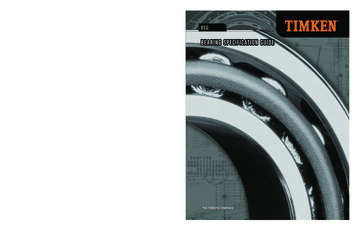
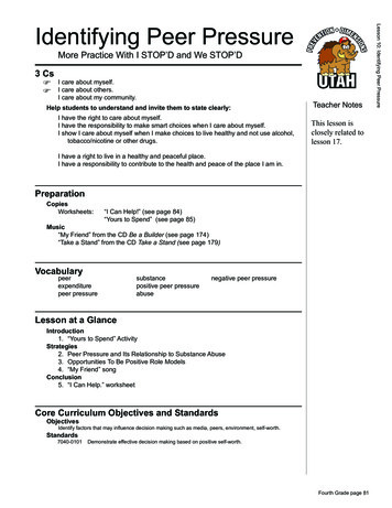
Recommended InstallationMethodsRECOMMENDED INSTALLATION STALLATIONMETHODSAn installation tool should always be used when installing an oil seal. The use of a toolwillmake theinstallationeasierlowerthepossibilityof nstallingseal.a heninstallingan anoilseal.TheTheuseuseof aoftoolmakeinstallationeasierlowerpossibilityof dandlowerthethepossibilityof sealcocking.Remove any burrs, nicks or grooves from the bore and shaft. Sharp edges should becoveredwitha nickslubricatedsleeveorboretapetoprotectthe edgesseallip.MakeRemoveburrs,nicksor assemblygroovesfromshaft.Sharpedgesshouldbe thatRemoveanyanyburrs,or used.Makesurethatthecoveredwitha lubricatedassemblysleeveor tapeto protectMakesurecoveredwitha lubricatedassemblysleeveor tapeto thethelubricantthatis thebeingretained.newfacesinsamedirectionas theoriginalone.Generally,facesnewsealsealfacesin thesamedirectionas theoriginalone.Generally,thethelip lipfacesthethelubricantis beingretained.lubricantthatthatis beingretained.Before installation, wipe the seal lip and shaft with the lubricant that is being retained.Theinstallation,O.D.of a stallation,wipethelipandshaftwiththelubricantis ined.helpstheseallipduringinitialrun-in.O.D.a nTheTheO.D.of aofrubbercoveredsealsealshouldalwaysbe tialrun-in.helpsthethesealseallip lipduringinitialrun-in.Select thethe correctcorrect installationinstallation tool.tool. installationtool.results,centerof orForbestbestresults,thethecenterof thetooltoolshouldbe beopenofseal!surfaceof thetheseal!tosurfacethatpressureisappliedonlyat theouteredge.Neverhammerdirectlyto thatpressureis appliedonlyat thesealsealouteredge.Neverhammerdirectlyon onthethesurfaceof theseal!surfaceof theseal!DIAMETER .020 TO .040 LESS THAN BORE DIA.DIAMETERTO .040LESSTHANBOREDIAMETER.020.020TO .040LESSTHANBOREDIA.DIA.INSTALLATION TOOLINSTALLATIONTOOLINSTALLATIONTOOLTOOL STOPS AGAINSTSUPPORT ACESUPPORTSURFACEHOUSINGHOUSINGHOUSINGMINIMUM DIAMETER .20 TO .40 LARGER THAN SEAL O.D.MINIMUMDIAMETER.20 .40TO LARGER.40 LARGERTHANSEALMINIMUMDIAMETER.20 TOTHANSEALO.D.O.D.INSTALLATION TOOLINSTALLATIONTOOLINSTALLATIONTOOLEE EHOUSINGHOUSINGHOUSINGWIDTH "E" TO CHAMFER WIDTH PLUS .020TOOL STOPS AGAINST HOUSING FACE.WIDTHTO CHAMFERWIDTHPLUSWIDTH"E" "E"TO E.TOOLSTOPSAGAINSTHOUSINGFACE.9
Recommended InstallationMethodsMINIMUM DIAMETER .20 TO .40 LARGER THAN SEAL O.D.INSTALLATION TOOLSURFACE STOPS TOOLSTRIKE PLATEHOUSING10HOUSING
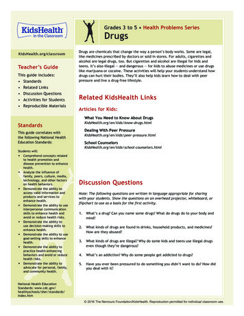
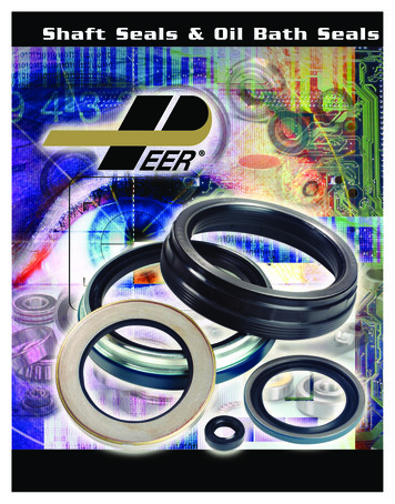
Improper Installation MethodsIMPROPER INSTALLATION METHODSIMPROPER INSTALLATION METHODSIMPROPER INSTALLATION METHODSSMALLDIA.SMALLDIA.SMALLDEFORMED SEALDIA.DEFORMED SEALINSTALLATION TOOLINSTALLATION TOOLDEFORMED SEALINSTALLATION TOOLHOUSINGHOUSINGHOUSINGDeformed seal.Deformed seal.Deformed seal.HOUSINGHOUSINGHOUSINGDeformed seal.Deformed seal.Deformed seal.INSTALLATION TOOLINSTALLATION TOOLINSTALLATION TOOLO.D. PEELINGO.D. PEELINGHOUSINGHOUSINGO.D. PEELINGHOUSINGCOCKED SEALCOCKED SEAL Misalignment(cocking).Misalignment (cocking).COCKED SEALMisalignment (cocking).11
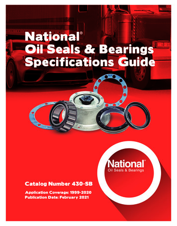
Standard Seal DesignsCase SymbolDescription andLip SymbolApplicationSTVK12BAMetal O.D. with groundMetal O.D. with an innersurface and front chamfer.case for lip protection andMost common andgreater structural rigidity.economical.CFRubber covered O.D. forimproved O.D. sealingability. Preferred for softalloy or plastic housings.Rubber covered O.D.Similar to design C.Preferred where corrosioncould be a problem.Single lip with agarter spring. Sealsin low pressure (up to7psi). Notrecommended in Dual lip with a garterspring. Seals in lowpressure (up to 7psi).Additonal dust lipprovides protectionfor the primary lip.Single lip without agarter spring. Sealsgrease or viscousfluids in a nonpressure medium.Also used for dustand dirt exclusion.Dual lip without agarter spring. Asstyle V above.Additional dust lipprovides protectionfor the primary lip.
Outer Case& Lip DesignationsOTHER CASE AND LIP DESIGNATIONSCASEDESIGNATIONSIt is important toOTHERnote that thereare aANDnumberLIPof sealslisted in this catalog that do notmatch the lip and case styles noted on the previous page. Please refer to the followinglists to help identify the designs that are not represented by a line drawing.Itis importantLipSymbol to note that there are a number of seals listed in this catalog that do notmatch the lip and case styles noted on the previous page. Please refer to the followinglists to help identify the designs that are not represented by a line drawing.D Double Lip, Double Spring LoadedO ExternalLipSymbol Seal TypeU Triple LipD DoubleLip, Double Spring LoadedCaseSymbolO External Seal TypeU Triple LipH Reverse Case StyleJCase SpecialFlanged Indented CaseSymbolM Fully Rubberized Inner CaseN Short Flex High Pressure DesignH SpecialReverseFeatureCase StyleS JY SpecialFlangedIndentedCaseDesign Variationfrom StandardM FullyRubberizedInnerCaseZ Rubber Covered ChamferN Short Flex High Pressure DesignS SpecialOther,more Featurecomplex designs are available for special applications. Please contact PEERY DesignVariationStandardif further assistanceis fromrequired.Z Rubber Covered ChamferOther, moreare availableMATERIALfor special applications.Please contact PEERLIP, complexCASE designsAND SPRINGDESIGNATIONSif further assistance is required.Lip, Case & Spring ONSUnless LIP,otherwisenoted,all casesand springsfor PEER sealsare produced using carbonsteel and all rubber coating and lips are produced using nitrile.LipMaterialCaseMaterialUnlessotherwise noted, all casesandMaterialsprings for PEER sealsSpringare producedusing carbonsteel and all rubber coating and lips are produced using nitrile.N NitrileC Carbon SteelC Carbon SteelP PolyacrylateS StainlessSteel(304)S StainlessSteel (304)Lip MaterialCase MaterialSpringMaterialS SiliconeT PTFENC Carbon SteelC Carbon SteelV NitrileFluoroelastomerP PolyacrylateS Stainless Steel (304)S Stainless Steel (304)S SiliconeT PTFEThedesignation for O.D. sealant on the outer case of the seal is an “-S” at the end of theV Fluoroelastomerpartnumber, for example, the part number POS22530037TB-S. This O.D. sealant isavailable on any metal case design, upon request.The designation for O.D. sealant on the outer case of the seal is an “-S” at the end of thepart number, for example, the part number POS22530037TB-S. This O.D. sealant isavailable on any metal case design, upon request.13
Engineering Information sheet14
Metric Conversion 34.921125.0055.000127.0015
A Complete Listing of PEERA COMPLETEShaftSealsLISTING OF PEER OIL SEALSThe following pages show a complete listing of seals that are already manufactured orcan be manufactured by PEER. Please note that the range of sizes and styles of sealsavailable from PEER is not limited to those listed in this catalog. PEER has thecapability to produce seals of many different sizes and styles. Special types of seals canalso be produced, according to your specific requirements. Please contact PEER directlyfor further assistance if you need help with a seal that is not listed in this catalog.The following section contains a listing of inch size seals immediately followed by alisting of metric sizes. After the product listing is a complete interchange for the inchsizes followed by the metric sizes.It is important to note that all seals manufactured by PEER begin with the prefix “POS”which stands for “PEER Oil Seals”. The “POS” signifies that the seal has beenmanufactured according to the exacting standards of PEER Bearing Company.Inch seals have a part number that is directly related to the critical dimensions of the seal.For example, the POS22530037TB-S is made for a 2.25” (2-1/4”) shaft, to fit intoapproximately a 3” housing bore, and is approximately .37” (3/8”) wide. The “TB”signifies a double lip seal with a garter spring and a single case configuration. The “-S”signifies that this particular seal has an O.D. sealant on the outer case of the seal. Pleasenote that exact dimensions of the seal, including the remainder of the decimaldimensions, can be found listed in this catalog.MetricMetric sealsseals havehave aa partpart numbernumber thatthat isis veryvery simplesimple toto understand.understand. ForForexample,example,thethePOS40567TC isis mademade forfor aa 40mm25mm shaft,shaft, 56mm56mm housinghousing bore,bore, andand 7mm7mm width.width. TheThePOS40567TCsignifies a double lip seal with a garter spring and a single case with a rubber“TC” signifiescovered O.D.O.D.covered16
Inch Parts Listing – Shaft SealsAll PEER Part #’s prefixed with “POS”PEER Part #ShaftBoreWidthLip Mat.PEER Part #ShaftBoreWidthLip 0751
Failed oil seals can often be traced back to improper handling or storage. Never store in unprotected open bins. Keep in the original packing. Keep seals clean. Never tag seals. Never hang seals on a hook. Avoid dropping seals. This may dislodge the spring, distort or contaminate the s