Transcription
GWPD 10—Estimating discharge from a pumped well byuse of a circular orifice weirVERSION: 2010.1PURPOSE: To estimate the discharge from a pumped well from a non-vertical standard pipe by using acircular orifice weir.Materials and Instruments1.Steel orifice plate2.Hand level3.Piezometer tube, 1/8-inch or 1/4-inch diameter4.Glass tube, 1/8-inch or 1/4-inch diameter5. Accurate yardstick, or other suitable ridged scale6.Graduated tape7.Pencil or pen, blue or black ink. Strikethrough, date, andinitial errors; no erasures8.Field notebook9.Groundwater Site Inventory (GWSI) System Groundwater Site Schedule, Form 9-1904-AData Accuracy and Limitations1. The circular orifice weir method is accurate to within2 percent.2. The hole in the steel plate of the orifice weir must beaccurately cut, be centered, be circular, and have a beveled edge. The steel plate restricts the flow through theorifice and creates a pressure head in the discharge pipe.3.For the orifice weir to function properly, the gate valvethat controls the rate of discharge must be placed at least10 pipe diameters from the piezometer tube connectionto keep pipe turbulence to a minimum.4. The piezometer tube must be completely free of anyobstruction and free of air bubbles when a reading ofthe pressure head is made. The head in the line is cor-related with discharge by use of tables calibrated for theparticular ratio between the orifice and the discharge pipediameters (table 1).5. The discharge pipe must be level, and the water flowfrom the end of the discharge pipe must fall freely.Advantages1. This method provides an accurate means of determiningthe discharge rate from turbine or centrifugal pumps.2.No special training is needed to use this method.Disadvantages1. This method cannot be used to measure the pulsatingflow from a piston pump.2. Well flow must be constant.Assumptions1. An appropriately sized orifice plate is available and wasbuilt accurately.2. The diameter of the orifice plate is less than eight-tenthsof the inside diameter of the pipe that serves as the channel of approach.3. The last 6 feet of the discharge line is level and containsa fitting that is screwed into a 1/8-inch or 1/4-inch tappedhole centered on the discharge line, exactly 24 inchesfrom the orifice plate.
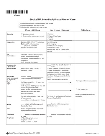
82 Groundwater Technical Procedures of the U.S. Geological SurveyInstructions1.2.3.Figure 1 shows the essential details for setting up acircular orifice weir for measuring the discharge rate ofa well that is being pumped with a turbine or centrifugalpump.Select an appropriately sized circular orifice weir andattach it to the end of the discharge pipe. Table 1 lists3- to 10-inch circular orifice weirs that can be used withdischarge pipes ranging from 4- to 12-inches in diameter.Place a short piece of glass tubing into the upper end ofthe piezometer tube. Attach the lower end of the piezometer tube to the fitting on the discharge line that is located24 inches from the orifice plate (fig. 1). Tape the piezometer tube to the scale making sure that the zero mark onthe scale lines up with the center of the piezometer fittingin the discharge pipe.4. The water level in the piezometer tube represents thepressure in the approach pipe when water is beingpumped through the orifice. The water level can beobserved in the glass tube.Between water-level readings, check for air bubbles inthe piezometer tube. If air bubbles are present, they canbe eliminated from the piezometer tube by dropping thetube between readings so that water flows from it.8.Record estimated discharge in the field notebook and inthe discharge data section of the GWSI Groundwater SiteSchedule (fig. 2, Form 9-1904-A).Data RecordingData are recorded in a field notebook. Discharge datashould also be recorded in the discharge data section of theGWSI Groundwater Site Schedule (Form 9-1904-A).ReferencesDriscoll, F.G., 1986, Groundwater and wells (2d ed.): St. Paul,Minnesota, Johnson Filtration Systems, Inc., 1089 p.Hoopes, B.C., ed., 2004, User’s manual for the National WaterInformation System of the U.S. Geological Survey, GroundWater Site-Inventory System (version 4.4): U.S. GeologicalSurvey Open-File Report 2005–1251, 274 p.5. To read the pressure head in the glass tube, hold thepiezometer tube in an upright position perpendicularto the discharge pipe. Read the water level using theattached scale.6.7.Determine the well discharge from table 1. For example,if the pressure head is 25.5 inches, the orifice plate is5 inches in diameter and the discharge pipe is 8 inchesin diameter; follow the 25.5-inch line from the left scaleuntil it intersects with the 5-inch orifice and 8-inch pipecolumn. The well discharge rate obtained from table 1 is500 gallons per minute.Layne & Bowler, Inc., 1958, Measurement of water flowthrough pipe orifice with free discharge: Memphis, TN,Layne & Bowler, Inc., Bulletin 501, p. 22–25.U.S. Geological Survey, Office of Water Data Coordination,1977, National handbook of recommended methods forwater-data acquisition: Office of Water Data Coordination,Geological Survey, U.S. Department of the Interior, chap. 2,p. 2-17.1/16 inch605959575655541/8 – 3/8 inchDetail oforifice platePiezometer tubeGate valve13121110987654321ScaleOrifice plate4 feet, minimum24 inchesFigure 1. Essential details of the circular orifice weir commonly used for measuringwelldischargewhendetailspumpingby circularmeans oforificea turbineDischargemust beFigure1. Essentialof thewerepump.commonlyused pipefor measuringlevel(Driscoll,1986).well discharge when pumping by means of a turbine pump. Discharge pipe must belevel (Ground Water and Wells, 1975).
GWPD 10—Estimating discharge from a pumping well by use of a circular orifice weir 83Table 1. Orifice table for measurement of water through pipe orifices with free discharge. Values are in gallons per minute to thenearest whole number. (Compiled by the Engineering Department of Layne and Bowier, Inc., from original calibrations by PurdueUniversity)—Continued[—; no data]Head,ininches3-inch orifice4-inchpipe6-inchpipe4-inch orifice5-inch orifice6-inch 2,5392,565
84 Groundwater Technical Procedures of the U.S. Geological SurveyTable 1. Orifice table for measurement of water through pipe orifices with free discharge. Values are in gallons per minute to thenearest whole number. (Compiled by the Engineering Department of Layne and Bowier, Inc., from original calibrations by PurdueUniversity)—Continued[—; no 49.53-inch nch nch nch 63,4433,460
GWPD 10—Estimating discharge from a pumping well by use of a circular orifice weir 85Table 1. Orifice table for measurement of water through pipe orifices with free discharge. Values are in gallons per minute to thenearest whole number. (Compiled by the Engineering Department of Layne and Bowier, Inc., from original calibrations by PurdueUniversity)—Continued[—; no .56464.56565.56666.56767.56868.56969.5703-inch 722732742752762772782804-inch 774794814834854874894915-inch 7817847877907937967998028058088116-inch �————————————
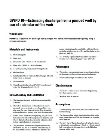
86 Groundwater Technical Procedures of the U.S. Geological SurveyFORM NO. 9-1904-ARevised Sept 2009, NWIS 4.9File CodeCoded byChecked byEntered byAGENCYCODE (C4)DateU.S DEPT. OF THE INTERIORGEOLOGICAL SURVEYGROUNDWATER SITE SCHEDULEGeneral Site DataSITE ID(C1)USGSPROJECT(C5)STATION NAME (C12/900)SITETYPE1 (C802)-PrimarySTATE (C7)COUNTRY (C41)DISTRICT (C6)SecondaryCOUNTY or TOWN (C8)County )CLAT/LONGMETHOD (C35)D GlandnetDGPSLGPSALTITUDEACCURACY(C18)M NLORAN mapALTITUDEMETHOD(C17)R S ULAT/LONGDATUM (C36)inter- reported survey unknownpolateddigital mapA D G IaltimeterDGPS 3North AmericanDatum of 1983L M N RLiDAR LevelLAND NET (C13)TOPOGRAPHICSETTING(C19)NAD27North AmericanDatum of 1927hilltopHYDROLOGICUNIT CODE(C20)1/4KsinkholeUunknownsectionLMH 1 5Hndrth tenthsec.sec.halfsec.S R F T M Usec.3sec.5sec.10sec.min. UnknownALTITUDE(C16)ALTITUDEDATUM(C22)National GeodeticNGVD29NAVD88North AmericanVertical Datum of 1929 Vertical Datum of 1988TtownshipOPlake or mangroveoffswamp swampshorepedimentDRAINAGEBASIN raingagetipping acoustic electro- pressurebucket velocity magnetic transducerrainmeter flowmetergageSTANDARD TIMEZONE (C813)DAYLIGHTSAVINGS TIMEFLAG (C814)Y OR NMAPSCALE (C15)MAP NAME(C14)AGENCYUSE (C803)Aactiveno/naDILdiscon- inactive activesitetinuedwrittenMDATA TYPE (C804)Place an 'A' (active), an'I' (inactive), or an 'O'(inventory) in theappropriate boxINSTRUMENTS (C805)(Place a "Y' in theappropriate corderORWLcontWLint2 NATIONALWATER-USE(C39)active inventory ORD READYFOR WEB (C32)monthdayyearREMARKS (C806)EVintwindvel.stillingwellYCR eady to condi- proprie- local usedisplay tionaltaryonlyFOOTNOTES1 SITE TYPE(C802)GLWEATESLALA -EXLA -OULA -SNKLA -SHLA utcropSinkholeSoil holeShoreOCOC -COLKSPSTST -CAST -DCHST -TSFA-WIWOceanCoastalLake, Reservoir,ImpoundmentSpringStreamCanalDitchTidal strea mWaste-Injection wellWS DO CO IN IR MI LV PH STwater domestic commer- industrial irrigation mining livestockcialsupplypowerwastehydrowaterelectric treatmentRM TE AQremediationthermoelectricpoweraquacultureFigure 1.2. ormForm9-1904-A.9-1904-A.GWGW -CRGW -EXGW -HZGW -IWGW -THGW -MWWellCollector or Ranney type wellExtensometer wellHyporheic -zone wellInterconnected wellsTest hole not completed as a wellMultiple wellsSBSB- CVSB-GWDSB-TSMSB-UZSubsurfaceCaveGroundwater drainTunnel, shaft, or mineUnsaturated zoneC22 Other (see manual for codes)C36 Other (see manual for codes)C39 is mandatory for all sites having data in SWUDS.
GWPD 10—Estimating discharge from a pumping well by use of a circular orifice weir 87GENERAL SITE DATACDATA RELIABILITY (C3)LMfieldpoorchecked locationUSE OFSITE(C23)USE OFWATER(C24)UDATE OF FIRST CONSTRUCTION alseismicheatreservoirmineobservationoil orgasAB CDE FHair bottling comm- de- power firecond.ercial alundatacheckedCunconfined confinedmultiplesingleI JKMXmixedSrecharge repressurizeMdomes- irriindus- miningticgation trial(cooling)confinedmultipleRNPmedi- hdrawalwastedestroyedRSTUYSECONDARY USEOF SITE(C301) (SeePRIMARYAQUIFER (C714)TERTIARYUSE OFSITE(C302) (Seeuse of site)use of site)SECONDARY USEOF WATER(C25) (see useZaqua- recrea- stock insti- unused desalin- otherculture tionstutionalationTERTIARYUSE OFWATER(C26)(see use of water)of water)NATIONALAQUIFER lydaySOURCEOF DEPTHDATA erRSZother reportingreported agencyotherWATER-LEVEL DATADATE WATER-LEVEL MEASURED (C235)dayyearWATER LEVEL(C237/241/242)land meas. verticalsurface pt. datumMP SEQUENCE NO. (C248)(Mandatory if WL type M)WATER-LEVELDATUM (C245)(Mandatory if WL type S)SITE STATUSFOR WATERLEVEL (C238)L M SWATER-LEVEL TYPECODE (C243)TIME (C709)monthANGVD29Batmos.tidepressure stageMETHOD OF WATER-LEVELMEASUREMENT(C239)WATER-LEVELACCURACY (C276)NAVD88North AmericanVertical Datum 0f 1988National GeodeticVertical Datum 0f 19290footCDicedry1FG9IJnearby injectorrecentlysiteflowingEDCanalog calibrated differairlineentialGPS2Hrecently flowing nearbyflowingflowingBAairlinetenthEOther (See manual for codes)GFestimatedMPERSON MAKINGMEASUREMENT (C246)(WATER LEVEL PARTY)OHLPMtrans- pressure calibrated geophysiducergage press. gage cal logsSOURCE OF WATER-LEVELDATA (C244)hunnot todredth nearestfootNinjector plugged measure- obstruc- umpednearbypumpingOTRPacoustic reportedpulsemano- non-rec. tanceSwelldestroyedTsteeltapeVXZaffected bysurfacewaterotherZelectric calibrated othertapeelec. sical ASURING AGENCY (C247)(SOURCE)EQUIP ID (C249)(20 char)REMARKS (C267)RECORD READY FOR(256 char)WEB (C858)YCready todisplayPLcondi- proprie- local usetionaltaryonlyCONSTRUCTION DATARECORD TYPE (C754)CON SNAME OF CONTRACTOR(C63)SOURCE OF DATA(C64)METHOD OFCONSTRUCTION (C65)TYPE OFFINISH (C66)DATE OF COMPLETEDCONSTRUCTION (C60)RECORD SEQUENCE NO. STVWZcabletooldughydraulicrotaryjettedair percussionreverserotarysonictrenchingdrivendrive screenhoriz.galleryopenendperf orslottedscreensandpointwalledopenholeotherMETHOD OF DEVELOPMENT (C69)TYPE OFSEAL(C67)Sother reportingreported agencybored oraugeredG2 - Groundwater Site ScheduleAothergov'tyearAFHOURS OF DEVELOPMENT (C70)dayair-rotaryCBOTTOM OF SEAL therABCJNPSZair-liftpumpbailedcompressed airjettednonepumpedsurgedotherSPECIAL TREATMENT (C71)CDEFHMZchemicalsdry other
88 Groundwater Technical Procedures of the U.S. Geological SurveyCONSTRUCTION HOLE DATA (3 sets shown)HO L ERECORD TYPE (C756)SEQUENCE NO. OF PARENT RECORD (C59)RECORD SEQUENCE NO. (C724)DEPTH TO TOP OFINTERVAL (C73)DEPTH TO BOTTOM OFINTERVAL (C74)DIAMETER OFINTERVAL (C75)RECORD SEQUENCE NO. (C724)DEPTH TO TOP OFINTERVAL (C73)DEPTH TO BOTTOM OFINTERVAL (C74)DIAMETER OFINTERVAL (C75)RECORD SEQUENCE NO. (C724)DEPTH TO TOP OFINTERVAL (C73)DEPTH TO BOTTOM OFINTERVAL (C74)DIAMETER OFINTERVAL (C75)CONSTRUCTION CASING DATA (4 sets shown)C S NGRECORD TYPE (C758)RECORD SEQUENCE NO. (C725)DEPTH TO TOP OFCASING (C77)SEQUENCE NO. OF PARENT RECORD (C59)DEPTH TO BOTTOM OFCASING (C78)4 CASING MATERIAL (C80)DIAMETER OFCASING (C79)CASING THICKNESS (C81)SEQUENCE NO. OF PARENT RECORD (C59)RECORD SEQUENCE NO. (C725)DEPTH TO TOP OFCASING (C77)DIAMETER OFCASING (C79)DEPTH TO BOTTOM OFCASING (C78)4 CASING MATERIAL (C80)CASING THICKNESS (C81)SEQUENCE NO. OF PARENT RECORD (C59)RECORD SEQUENCE NO. (C725)DEPTH TO TOP OFCASING (C77)4DIAMETER OFCASING (C79)DEPTH TO BOTTOM OFCASING (C78)CASING MATERIAL (C80)CASING THICKNESS (C81)SEQUENCE NO. OF PARENT RECORD (C59)RECORD SEQUENCE NO. (C725)DEPTH TO TOP OFCASING (C77)4DIAMETER OFCASING (C79)DEPTH TO BOTTOM OFCASING (C78)CASING MATERIAL (C80)CASING THICKNESS (C81)FOOTNOTE:4 CASING MATERIALCODESA B CabsDEF G HIJK L M NP Qbrick concrete copper PTFE Fiber- galv. Fiber- wrought Fiber- PVC glass other PVC PVC or FEPiron glass threadmetal glued plasticglass iron glassplasticepoxyedRS T U Vrock or steelstoneW X YZ4 6tile coated stain- wood steel steel other stain- staincarbon galva- mat. less lesssteel lessnizedsteel304 316Groundwater Site Schedule - 3
GWPD 10—Estimating discharge from a pumping well by use of a circular orifice weir 89CONSTRUCTION OPENINGS DATA (3 sets shown)RECORD TYPE (C760)O P E NRECORD SEQUENCE NO. (C726)SEQUENCE NO. OF PARENT RECORD (C59)DEPTH TO BOTTOM OFINTERVAL (C84)DEPTH TO TOP OFINTERVAL (C83)5MATERIAL TYPE (C86)6 TYPE OF OPENINGDIAMETER OFINTERVAL (C87)LENGTH OF OPENING(C89)(C85)WIDTH OF OPENING(C88)RECORD SEQUENCE NO. (C726)DEPTH TO TOP OFINTERVAL (C83)DIAMETER OFINTERVAL (C87)DEPTH TO BOTTOM OFINTERVAL (C84)5MATERIAL TYPE (C86)6 TYPE OF OPENINGWIDTH OF OPENING(C88)LENGTH OF OPENING(C89)(C85)RECORD SEQUENCE NO. (C726)DEPTH TO TOP OFINTERVAL (C83)DIAMETER OFINTERVAL (C87)DEPTH TO BOTTOM OFINTERVAL (C84)5MATERIAL TYPE (C86)6 TYPE OF OPENINGWIDTH OF OPENING(C88)LENGTH OF OPENING(C89)(C85)FOOTNOTES:5 TYPE OF MATERIAL CODES FOROPEN SECTIONSA BCDEF G HJIKLABS brass concrete ceramic PTFE fiber- galv. fiber- wrought fiber- PVC glassorglass iron glassironglass threadbronzeplasticepoxyedNMothermetalPPVC PVCgluedQRSFEPstainlesssteelsteelTtileVbrickWX Y Z 4 6mem- steel steel other stain- stainbrane carbon galvaless lessnized304 3166 TYPE OF OPENINGS CODESFfracturedrockLlouvered orshutter-typeMmeshscreenPperforated,porous reenWwalled orshoredXopenholeZotherCONSTRUCTION MEASURING POINT DATARECORDTYPE(C766)MP N TM.P. HEIGHT (C323)ALTITUDEDATUM(C328)RECORDSEQUENCENO. (C728)BEGINNINGDATE(C321)monthALTITUDE OFMEASURINGPOINT LTITUDEACCURACY(C327)M.P. REMARKS (C324)RECORD READY FORWEB (C857)Yready todisplay4 - Groundwater Site ScheduleCPLcondi- proprie- local usetionaltaryonly
90 Groundwater Technical Procedures of the U.S. Geological SurveyCONSTRUCTION LIFT DATARECORD TYPE(C752)DATERECORDED(C38)L I F TmonthRECORD SEQUENCENO. (C254)dayPUMPINTAKEDEPTH (C44)yearHORSEPOWERRATING(C46)TYPE OF TYPE OFPOWER (C45)MANUFACTURER(C48)STsubmer- turbinesibleDEGHLNdieselelectricgasolinehandLP gasnaturalgasUXZunknownno liftotherS WsolarwindmillZotherSERIAL NO.(C49)POWER COMPANY ACCOUNTNUMBER (C51)POWER COMPANY (C50)POWER METERNUMBER (C52)PUMP RATING (C53)(million gallons/units of fuel)PERSON OR COMPANYMAINTAINING PUMP (C54)ADDITIONAL LIFT(C255)RATED PUMP CAPACITY(gpm) (C268)STANDBY POWER (C56)(see TYPE OF POWER)HORSEPOWER OF STANDBY POWER SOURCE (C57)MISCELLANEOUS OWNER DATARECORD TYPE (C768)WU OWNERTYPE(C350)CPCorporationOWN RGVGovernmentRECORD SEQUENCE NO. SupplierDATE OF OWNERSHIP (C159)END DATE OF OWNERSHIP (C374)OWNER'SNAME(C161)EXAMPLES:JONES, RALPH A.JONES CONSTRUCTION COMPANYOWNER'SPHONENUMBER(C351)ACCESS TOOWNER'SNAME(C352)0P ublicAcces s1C ooperator2US G SOnly34Dis trict P roprietaryOnlyOWNER'S ADDRESS(LINE 1)(C353)OWNER'S ADDRESS(LINE 2)(C354)OWNER'S CITYNAME(C355)OWNER'S ZIPCODE (C357)STATE (C356)OWNER'S COUNTRYNAME(C358)ACCESS TO OWNER'SPHONE/ADDRESS(C359)0P ublicAcces s1C ooperator23US G SOnly4Dis trict P roprietaryOnlyMISCELLANEOUS VISIT DATARECORD TYPE (C774)V I S TRECORD SEQUENCE NO. (C737)DATE OF VISIT (C187)monthdayyearNAME OF PERSON (C188)Groundwater Site Schedule - 5
GWPD 10—Estimating discharge from a pumping well by use of a circular orifice weir 91MISCELLANEOUS OTHER ID DATA (2 sets shown)RECORD TYPE (C770)O T I DRECORD SEQUENCENO. (C736)OTHER ID (C190)ASSIGNER (C191)RECORD SEQUENCENO. (C736)OTHER ID (C190)ASSIGNER (C191)MISCELLANEOUS OTHER DATAO T D TRECORD TYPE (C772)RECORD SEQUENCE NO. (C312)OTHER DATATYPE (C181)OTHER DATA LOCATION ngAgencyotherDATA FORMAT CELLANEOUS LOGS DATA (3 sets shown)RECORD TYPE (C778)L OG SRECORD SEQUENCE NO. (C739)ENDINGDEPTH(C201)BEGINNINGDEPTH(C200)DATA FORMAT (C225)RECORD TYPE (C778)RECORD TYPE (C778)FMPZmachinereadablepublishedotherL OG SRECORD SEQUENCE NO. (C739)FMPZmachinereadablepublishedotherL OG SMPZpublishedotherACOUSTIC LOG:AS SonicAV Acoustic velocityAW Acoustic waveformAT Acoustic televiewerCALIPER LOG:CP CaliperCS Caliper, single armCT Caliper, three armCM Caliper, multi armCA Caliper, acousticDRILLING LOG:DT Drilling timeDR DrillersDG GeologistsDC CoreELECTRIC LOG:EE ElectricER Single-point resistanceEP Spontaneous potentialEL Long-normal resistivityES Short-normal resistivityEF Focused resistivityET Lateral resistivityEN MicroresistivityEC Microresistivity, forusedEO Microresistivity, lateralED Dipmeter6 - Groundwater Site ScheduleA D Gothergov'tSOURCE OFDATA(C202)machinereadableNUCLEAR LOG:NG GammaNS Spectral gammaNA Gamma-gammaNN NeutronNT Neutron activitationNM Neuclear magneticresonanceM ORmemory ownerotherreportedSZreporting otheragencydrillergeologistLM ORlogsmemory ownerotherreportedSZreporting otheragencyA D Gothergov'tdrillergeologistLM ORlogsmemory ownerotherreportedSOPTICAL LOG:OV VideoOF Fisheye videoOS Sidewall videoOT Optical televiewerCOMBINATION LOG:ZF Gamma, fluidresistivity, temperatureZI Gamma, electromagneticinductionZR Long/short normalresistivityZT Fluid resistivity,temperatureZM Electromagnetic flowmeter,fluid resistivity,temperatureZN Long/short normalresistivity, spontaneouspotentialZP Single-point resistance,spontaneous potentialZE Gamma, long/shortnormal resistivity,spontaneous potential,single-point resistance,fluid resitivity,temperatureWELL CONSTRUCTION LOG:WC Casing collarWD Borehold deviationOTHER LOG:OR OtherZreporting otheragencyOTHER DATALOCATION (C226)ELECTROMAGNETIC LOG:MM Magnetic logMS Magnetic susceptibiity logMI Electromagnetic induction logMD Electromagnetic dual induction logMR Radar reflection image logMV Radar direct-wave velocity logMA Radar direct-wave amplitude logFLUID LOG:FC Fluid conductivityFR Fluid resistivityFT Fluid temperatureFF Fluid differential temperatureFV Fluid velocityFS Spinner flowmeterFH Heat-pulse flowmeterFE Electromagnetic flowmeterFD Doppler flowmeterFA Radioactive tracerFY Dye tracerFB Brine tracerLlogsTYPE OF LOG (C199)ENDINGDEPTH(C201)FgeologistOTHER DATALOCATION (C226)RECORD SEQUENCE NO. (C739)filesdrillerTYPE OF LOG (C199)SOURCE OFDATA(C202)filesA D Gothergov'tOTHER DATALOCATION (C226)ENDINGDEPTH(C201)BEGINNINGDEPTH(C200)DATA FORMAT (C225)SOURCE OFDATA(C202)filesBEGINNINGDEPTH(C200)DATA FORMAT (C225)TYPE OF LOG (C199)
92 Groundwater Technical Procedures of the U.S. Geological SurveyMISCELLANEOUS NETWORK DATA (3 types shown)RECORD TYPE(C780)TYPE OFANALYSIS(C120)N E esticidesnutrientssanitaryanalysisN E C,D&Eall ormostcodesB&C&radioactivecodesB,C&Aother8TYPE OFNETWORK(C706)RECORD SEQUENCENO. (C730)WLwaterlevelMETHOD OFCOLLECTION(C133)7 FREQUENCY OFCOLLECTION (C118)WDpumpageor withdrawalsCcalculatedENETWORKSITE (C708)BEGINNINGYEAR (C115)ENDINGYEAR (C116)8 SECONDARYNETWORKSITE (C257)TYPE OFNETWORK(C706)RECORD SEQUENCENO. (C730)8SECONDARYPRIMARYNETWORKSITE (C257)8 PRIMARYCOLLECTION (C118)SOURCEAGENCY (C117)ENDINGYEAR (C116)waterquality7 FREQUENCY OFN E TWBEGINNINGYEAR (C115)ANALYZINGAGENCY (C307)COLLECTION (C118)SOURCEAGENCY (C117)RECORD TYPE(C780)GcodesD&B7 FREQUENCY OFSOURCEAGENCY (C117)RECORD TYPE(C780)TYPE OFNETWORK(C706)RECORD SEQUENCENO. (C730)NETWORK SITE (C708)BEGINNINGYEAR (C115)Mesti- metermatededUZunknownotherSWENDINGYEAR (C116)8 SECONDARY8 PRIMARYNETWORKSITE (C257)NETWORKSITE (C708)FOOTNOTES:A7 FREQUENCY OF COLLECTIONCODES8annuallyNETWORK SITE roject,DFIdailysemimonthlyintermittentMOQmonthly one-time every 3yearsevery 4years5Xevery 5 every 10yearsyears4cooperator,MISCELLANEOUS REMARKS DATA (4 types shown)RECORD TYPE(C788)RMK SRECORD SEQUENCE NO. (C311)DATE OF REMARK (C184)REMARKS (C185)monthdayyearmonthdayyearSubsequent entries may be used to continue the remark. Miscellaneous remarks field is limited to 256 characters.RECORD TYPE(C788)RMK SRECORD SEQUENCE NO. (C311)DATE OF REMARK (C184)REMARKS (C185)Subsequent entries may be used to continue the remark. Miscellaneous remarks field is limited to 256 characters.Groundwater Site Schedule - 7
GWPD 10—Estimating discharge from a pumping well by use of a circular orifice weir 93DISCHARGE DATARECORD SEQUENCE NO. (C147)DATE DISCHARGEMEASURED (C148)monthTYPE OFDISCHARGE(C703)yeardayFflowDISCHARGE (gpm)(C150)SOURCE OF DATA (C151)ACCURACY OFDISCHARGEMEASUREMENT (C310)EGFPADothergov'texcellent goodfairpoor(LT 2%), (2%-5%) (5%-8%) (GT 8%)METHOD rDopplermete
GWPD 10—Estimating discharge from a pumped well by use of a circular orifice weir VERSION: 2010.1 PURPOSE: To estimate the discharge from a pumped well from a non-vertical standard pipe