Transcription
HDPE Standard Practice (3/5/2018)THIS STANDARD PRACTICE WAS DEVELOPED AS A GUIDE TO ASSIST THE ACPAINFRASTRUCTURE COMMITTEE’S MARKET TEAMS IN CREATING OR MODIFYINGSPECIFICATIONS IN THEIR MARKET AREAS. IT IS EXPECTED THAT CERTAIN PORTIONS OFTHIS STANDARD MAY NOT BE APPLICABLE TO ALL MARKETS. SOME OF THE CONTENTS INTHIS DOCUMENT COULD BE COPYRIGHTED. AS SUCH, THE USER SHOULD NOT “CUT ANDPASTE” LARGE SECTIONS OF THIS DOCUMENT AND PLACE INTO A NEW OR EXISTINGSPECIFICATION. THIS IS AN INTERNAL DOCUMENT INTENDED FOR THE USE OF ACPAMEMEBERS WORKING WITH AGENCIES TO IMPROVE THEIR SPECIFICATIONS, BUT IT SHOULDNOT BE DISTRIBUTED TO OUTSIDE AGENCIES.STANDARD PRACTICE FOR THE DESIGN AND CONSTRUCTION OF HIGHDENSITY POLYETHYLENE PIPE (HDPE)PART 1:GENERAL1.01 SCOPEA.This standard practice covers the design and construction of High DensityPolyethylene (HDPE) pipe for use in installations within the .B.Buried HDPE pipes are a composite structure consisting of a plastic tube and thesurrounding soil envelope. Both the plastic tube and soil envelope play a vital partin the structural design requirements for HDPE pipes. It is essential that the designerand installer recognize that the composite soil-pipe interaction in a typical trenchinstallation is comprised of the select embedment zone soils immediately surroundingthe pipe and the native trench wall soils. The interaction of these materials can playa significant role in the overall pipe's structural performance.C.Part 2 presents the design method for HDPE pipe design using the standardinstallation configurations that are specified herein. The limit states design methodpresented herein evaluates the pipe for deflection, thrust, strain, localize buckling andglobal buckling.D.Part 3 presents the construction requirements for thermoplastic pipe designed andinstalled in accordance with this standard practice.E.This standard practice shall be used as a reference by ACPA Infrastructure MarketTeams to assist in modifying existing agency standard specifications or specificproject specifications. It is not intended to be shared with specifying agencies.F.The design procedures given in this standard are intended for use by engineers whoare familiar with the concept of soil-pipe interaction and of the factors that mayimpact both the performance of the pipe and of the soil envelope. Before using thedesign procedures given in Part 2, the engineer should review the guidance andrequirements given in other sections of this standard practice and its accompanyingcommentary.Page 1 of 56
HDPE Standard Practice (3/5/2018)G.The values of dimensions and quantities are expressed in English unit values.1.02 APPLICABLE DOCUMENTSA. AASHTO (American Association of State Highway and Transportation Officials)AASHTO LRFD Bridge Construction SpecificationsAASHTO LRFD Bridge Design SpecificationsM43 Standard Specification for Sizes of Aggregate for Road and BridgeConstructionM145 Standard Specification for Classification of Soils and Soil-AggregateMixtures for Highway Construction PurposesM294 Standard Specification for Corrugated Polyethylene Pipe, 300 to 1500 mm(12 to 60 in.) DiameterPP63-09 Standard Practice for Pipe Joint Selection for Highway Culvert and StormDrainsB. AREMA (American Railway Engineering and Maintenance-of-Way Association)AREMA Manual for Railway EngineeringC. ASTM (ASTM International)C923 Standard Specification for Resilient Connectors Between ReinforcedConcrete Manhole Structures, Pipes, and LateralsD420 Standard Guide to Site Characterization for Engineering Design andConstruction PurposesD698 Standard Test Methods for Laboratory Compaction Characteristics of SoilUsing Standard EffortD1586 Standard Test Method for Standard Penetration Test (SPT) and Split-BarrelSampling of SoilsD2321 Standard Practice for Underground Installation of Thermoplastic Pipe forSewers & Other Gravity-Flow Applications.D2412 Standard Test Method for Determination of External LoadingCharacteristics of Plastic Pipe by Parallel-Plate LoadingD2487 Standard Practice for Classification of Soils for Engineering Purposes(Unified Soil Classification System)D3212 Standard Specification for Joints for Drain and Sewer Plastic Pipes UsingFlexible Elastomeric SealsD3350 Standard Specification for Polyethylene Plastics Pipe and Fittings MaterialsD5397 Standard Test Method for Evaluation of Stress Crack Resistance ofPolyolefin Geomembranes Using Notched Constant Tensile Load TestF477 Standard Specification for Elastomeric Seals (Gaskets) for Joining PlasticPipeF894 Standard Specification for Polyethylene (PE) Large Diameter Profile WallSewer and Drain PipePage 2 of 56
HDPE Standard Practice (3/5/2018)D. AWWA (American Water Works Association)M45 Manual of Practice for Fiberglass Pipe DesignE. OSHA (Occupational Safety and Health Standards)29 CFR Part 1926, OSHA Standards for the Construction Industry1.03 DEFINITIONSFigure 1 illustrates the definitions and limits of the terms: foundation, bedding, haunching,initial backfill, final backfill, pipe zone, pipe embedment, pipe width, excavated trenchwidth and springline as used in this standard practice.Note: Drawing not to scale.Figure 1 – Standard Terminology11Standard, A. S. T. M. (2014). D2321-14e1 Standard Practice for the Underground Installation of ThermoplasticPipe for Sewers and Other Gravity-flow Applications. ASTM International, West Conshohocken, PA.Page 3 of 56
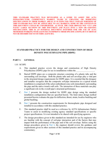
HDPE Standard Practice (3/5/2018)1.04 SUMMARY OF STANDARD PRACTICE APPROACHA. The design approach of this standard practice is based upon the assumptions inherentin the original Spangler load distribution2 for flexible pipe. In this approach, the verticalreaction on the bottom of the pipe is equal to the vertical load on the top of the pipe andis equally distributed over the bedding. Passive horizontal pressures on the sides of thepipe have a parabolic distribution over the middle 100 degrees of the pipe (see Figure2).Figure 2 – Load Distribution Based on Spangler3B. Earth load effects are computed based upon the pressure distributions presented herein.While both embankment loading and trench loading nomenclature are presented forclarity, all design is based upon developing full prism loads as opposed to Marston loadtheory.2Watkins, R. K., & Spangler, M. G. (1958). Some Characteristics of the Modulus of Passive Resistance of Soil: AStudy in Similitude. In Highway Research Board Proceedings (Vol. 37).3Association, U. B. P. P. (2013). Handbook of PVC Pipe Design and Construction. Industrial Press.Page 4 of 56
HDPE Standard Practice (3/5/2018)C. Soil stiffness values (modulus of soil reaction, E') for material in the embedment zoneare based upon the research of Duncan and Hartley4 and McGrath5. The soil stiffnessvalues to be utilized in design are based upon a direct substitution of the onedimensional constrained modulus, Ms, for E'. In the absence of direct measurement ofconstrained modulus values, the design values presented in Table 12.12.3.5-1 of theAASHTO LRFD Bridge Design Specifications are recommended for use herein.D. The soil stiffness values should be further modified, if required, based on the trenchwidth and the nature and properties of native soils encountered in accordance with theprocedure articulated in AWWA Manual of Practice M456. Leonhardt Factor.E. Lastly, the Modified Iowa formula, as developed by Spangler-Watkins, should becorrected to solve for vertical as opposed to horizontal deflection in accordance withthe procedure proposed by Masada7 and reproduced herein and the recommendationspresented in Part 2 of the Standard Practice.4Hartley, J. D., & Duncan, J. M. (1987). Eʹ and its variation with depth. Journal of Transportation Engineering,113(5), 538-553.5McGrath, T. J. (1998). Replacing E' with the Constrained Modulus in Flexible Pipe Design. In Pipelines in theConstructed Environment.6AWWA. (1995). Manual M45, Fiberglass Pipe Design Manual.7Masada, T. (2000). Modified Iowa Formula for Vertical Deflection of Buried Flexible Pipe. Journal ofTransportation Engineering, 126(5), 440-446.Page 5 of 56
HDPE Standard Practice (3/5/2018)PART 2: DESIGN2.01 GENERALA.Design criteria and methodology shall conform to the applicable sections of thisstandard practice.B.The designer shall carry out design checks in accordance with this standard practiceto ensure that the maximum localized distortion and net tension strain of the installedthermoplastic pipe shall not exceed the specified limits based upon the pipe selectedfor use, the embedment material properties specified, the native soil conditions thatare anticipated to be encountered, and the installation configuration specified.C.The native soil component can significantly impact both short and long-term pipeperformance, and its impact may vary with both trench configuration and embedmentmaterial selection. The designer shall clearly indicate the combination of native soils,embedment soils, and installation configuration assumed in design. This informationshall be provided to the installer in the manner prescribed by Article 2.02, ParagraphB.2.02 DESIGN REQUIREMENTSA.General Design Approach1.The performance limits for thermoplastic pipe include: wall crushing (stress),localized wall buckling, reversal of curvature (over-deflection), excessivedeflection (i.e., deflection that compromises functional performance), strainlimits, longitudinal stresses, shear loadings, and fatigue.2.The designer should understand that he alone is responsible for carrying out allnecessary performance limit checks for each specific design situation.3.The three parameters that are essential in flexible pipe design include: load(design fill height, surcharge loads and live loads), soil stiffness in the pipe zone(both embedment and native soil), and pipe stiffness.4.Soil is a major component in developing soil-pipe interaction. The designermust take this into account during design and properly communicate/specifythe soil requirements to the installer and field inspector. Should the installer orfield inspector identify soil conditions in the field differing from those specifiedby the designer, the design should be modified to account for the actual fieldconditions.5.The design process, therefore, consists of:a.Determining external loading conditions,b.Assessing whether any special design conditions other than conventionaltrench and/or embankment loadings will govern in design,c.Determining or estimating in-situ soil conditions based on either sitespecific geotechnical investigations or experience,d.Selection of the desired balance of soil and pipe stiffness to meet theanticipated loading conditions for the duration of the design period, andPage 6 of 56
HDPE Standard Practice (3/5/2018)e.B.Articulating the assumptions utilized in design to the installer to ensurethat any conditions that arise or become apparent during construction thatare at variance with the design assumptions can be reviewed to confirmwhether the design is still valid or requires some modification to meet thedesign objective.Minimum Information Transfer to Contractor and Contract Administrator: Theminimum level of information transfer to the installer for each design where the useof flexible thermoplastic pipe is contemplated includes:1.Pipe material and minimum pipe stiffness2.Assumed installation configuration3.Embedment material and required placement density4.Assumed embedment width and assumed native soil characteristics (qualitativedescription and E'native value)2.03 PIPE MATERIAL REQUIREMENTSA.Pipe material requirements are general pipe material requirements to conform to thisStandard Practice. They are not to be construed as general approval for the use ofthese products within the . Specific products approvals areaddressed by the on a product-by-product basis outside of thisStandard Practice.B.Polyethylene (PE) Profile Wall Products1.Closed profile and open profile PE pipe products and fittings shall conform tolatest version of ASTM D3350 for all basic material requirements andmanufactured quality and dimensional tolerance for sanitary and storm sewerapplications in accordance with AASHTO M294 and ASTM F894.2.Materials used for pipe and fabricated fittings shall come from a singlecompound manufacturer and shall be made from virgin polyethylenecompounds having the minimum cell classifications as provided in Table 1:Table 1 – Minimum Cell Classifications for Pipe and Fabricated FittingsOutside Profile,Lining,Corrugations Inside Waterway WallProductStorm Sewer and Fabricated Fittings324432 C, or324432 E324432 C, or324432 ESanitary Sewer and Fabricated Fittings324432 C, or324432 E324432 C, or324432 E3.Resin compounds shall be tested for slow crack growth resistance in accordancewith Appendix SP-NCTL in ASTM Standard D5397.2.04 BEDDING AND FOUNDATION MATERIAL REQUIREMENTSPage 7 of 56
HDPE Standard Practice (3/5/2018)A.Classification of Materials: Materials for use as foundation, embedment, and backfillare classified in Table 2. They include natural, manufactured, and processedaggregates and the soil types classified according to ASTM Test Method D2487.Table 2 – Classes of Embedment and Backfill MaterialsASTM D2321ASTM D 2487SoilPercent PassingAASHTO AASHTOGroupClass Description SymbolASTM D 2321AtterbergDescriptionLimitsNo.M 43M 145SymbolSymbol1-1/2"None100%3/8"No. 4200LLPIUniformit CurvaytureCUCCN/AN/A 41 to 3Angular, crushedstone or rock,crushed grav el,CrushedIArock,NoneangularBbroken coral,#5, #56Ccrushed slag,#57C, #8cinders or shells; 25% 15% 12% Non Plastic#67large v oid content,contain little or nofines.Well-graded sandsGWand grav elly sands;little or no fines.Poorly -graded sandsCoarse-GPlittle or no fines.GrainedSoils;clean.and grav elly sands;#5#6 50%ofcoarse#56, #57fraction#67100%Well-graded sandsSWand grav elly sands;SPD 5%A1, A3 1 or 3Non Plastic 6 50%little or no fines.II 41 to 3ofPoorly -graded sandscoarseand grav elly sands;fraction 6little or no fines. 1 or 3CoarseGrainedSoils;borderlineclean w /e.g.,GW-GC,SP-SMSands and grav elsw hich are borderlinebetw een clean andNone100%w ith fines.Varies5% to12%Same as forNon PlasticGW, GP, SWand SP.fines.ABCDClass I materials allow for a broader range of fines than previous versions of ASTM D2321. When specifying Class I materialfor infiltration systems, the engineer shall include a requirement for an acceptable level of fines.All particle faces shall be fractured.Assumes less than 25% passes the 3/8” sieve.Class IV materials require a geotechnical evaluation prior to use and should only be used as backfill under the guidance of aqualified engineer.Page 8 of 56
HDPE Standard Practice (3/5/2018)Table 2 – Classes of Embedment and Backfill Materials (continued)ASTM D2321ASTM D 2487SoilPercent PassingAASHTO AASHTOGroupClass Description SymbolASTM D 2321AtterbergDescriptionM 43M 145SymbolSymbolLimitsNo.1-1/2"3/8"No. 4200LLGrav el &GMytureCUCCN/AN/AN/AN/A 4Sitly grav els, grav el- sand w ithsand-silt mix tures.PIUniformit Curva-or 10%fines 50%"A"ofLinecoarseCoarseGrainedfractionClay ey grav els,GCgrav el-sand-clay12% tomix tures.Soils; w ithA-2-4,fines.SM50%SCA-2-5, 4or mix tures.A-4 or Aw ithClay ey sands, sand-moreclay mix tures. 50%"A"ofLinecoarse100% 7 &fraction "A"than 30%Lineretainedv ery fine sands,on the 4rocks flour, silty or#200or clay ey fine sands,siev eFine-silts w ith slightGrainedplasticity .Soils;Inorgainic clay s ofinorganic.low to mediumCLLineA-2-6, orInorgainic silts andML "A"N/ASilty sands, sand-silt6 soilsIII 7&"A" 30%100%(retained)Line 50% 7&plasticity , grav ely "A"clay s, sandy clay s,Linesilty clay s, leanclay s.Inorgainic silts andv ery fine sands,MLIVErocks flour, silty orclay ey fine sands, 4N/AA-2-7 orA-4 or A-"A"6 soilsLineFine-silts w ith slightGrainedplasticity .Soils;Inorgainic clay s ofor lessinorganic.low to mediumretainedCLplasticity , grav elyclay s, sandy clay s,w ith 30%N/Aor 30%100%on #200siev esilty clay s, lean100%(retained) 50% 7& "A"Lineclay s.EUniform fine sands (SP) with more than 50% passing a 100 sieve behave like silts and should be treated as Class III soils ifallowed.Page 9 of 56
HDPE Standard Practice (3/5/2018)Table 2 – Classes of Embedment and Backfill Materials (continued)ASTM D2321ASTM D 2487SoilPercent PassingAASHTO AASHTOGroupClass Description SymbolASTM D 2321AtterbergDescriptionM 43M 145SymbolSymbolLimitsNo.1-1/2"3/8"No. 4200LLytureCUCCN/AN/AInorganic silts,Fine-micaceous orGrainedMHSoils;diatomaceous fine "A"N/ALinesandy or silty soils,inorganic.100%elastic silts.100% 50% 50Inorganic clay s ofOrganicCHSoilshigh plasticity , fat "A"N/ALineclay s.VFOrganic silts andOLorganic silty clay s of 4A5, A7N/A 50low plasticity .HighlySoilsOHmedium to highplasticity , organic100%PTorganic soils.100%"A" 50%N/A 50silts.Peat and other highor LineOrganic clay s ofOrganicFPIUniformit Curva- "A"LineN/AClass V materials shall not be permitted as bedding and backfill material.B.Installation and Intended Use of Materials1.Table 3 provides recommendations on installation and use based on class of soilor aggregates and their location in the trench.2.Class I (manufactured crushed stone) and Class II (AASHTO A1 and A3)materials are highly preferred for use in the foundation and embedmentzones. When properly placed, these materials provide a high degree of stiffnessand strength in limiting long term pipe deflection as compared to Class III andClass IV materials. Depending on the gradation and the in situ conditions, theuser is advised that geotechnical fabric may be warranted to prevent themigration of fines.3.Class III (AASHTO A2-4, A2-5, A2-6, A-4 and A-6) materials contain apercentage of clays and silts. Being such, Class III materials are sensitive tomoisture, require a high degree of compactive effort and control. As comparedto Class I and Class II materials, Class III materials are less stiff and offer lessstrength in limiting long term pipe deflection.4.Class IV (AASHTO A2-7, A-4 and A-6) materials contain a percentage of claysand silts. Compared to Class III materials, Class IV materials are highlysensitive to moisture, require a higher degree of compactive effort andcontrol. Class IV material are less stiff and offer less strength in limiting longterm pipe deflection.5.Class V (AASHTO A5 and A7) Soils, and frozen materials are not recommendedfor embedment These types of materials should be excluded and avoided fromthe embedment zone.Page 10 of 56
HDPE Standard Practice (3/5/2018)Page 11 of 56
HDPE Standard Practice (3/5/2018)Table 3 – Recommendations for Installation and Use of Soils and Aggregates for Foundation, andPipe-Zone Embedment8ASoil Classes (See Table 2)Class IBClass IIClass IIIClass IVGeneral Recom-Acceptable and commonWhere hydraulic gradientDo not use where watermendations andwhere no migration isexists check gradation toconditions in trench prevent stiffness. Do not use whereRestrictionsprobable or when combined minimize migration. Cleanwith a geotextile filtergroups are suitable for useproper placement andcompaction. Notmedia. Suitable for use as a as a drainage blanket andrecommended for use with and compaction. Notdrainage blanket and under underdrain (see Table 2).drain where adjacentUniform fine sands (SP)pipes with stiffness of 9 psi recommended for use withor less.pipes with stiffness of 9 psimaterial is suitably gradedwith more than 50 %or when used with apassing a #100 sievegeotextile filter fabric.(0.006 in.) behave like siltsand should be treated asDifficult to achieve high-soilwater conditions in trenchprevent proper placementor less.Class III soils.Foundation BeddingSuitable as foundation andSuitable as foundation andSuitable for replacing over- Suitable for replacing over-for replacing overexcavated and unstablefor replacing overexcavated and unstableexcavated trench bottom as excavated trench bottom forrestricted above. Install and depths up to 12 in. astrench bottom as restrictedtrench bottom as restrictedcompact in 6 in. maximum restricted above. Use onlyabove.above. Install and compact layers.in 12 in. maximum layers.where uniform longitudinalsupport of the pipe can bemaintained, as approved bythe engineer. Install andcompact in 6 in. maximumlayers.BeddingSuitable as restrictedSuitable as restrictedSuitable as restrictedSuitable as restrictedabove. Work material under above. Work material under above. Difficult to place and above. Difficult to place andpipe to provide uniformpipe to provide uniformcompact in the haunchcompact in the haunchhaunch support.Minimum Recom-See Notehaunch support.Cmended PercentCompaction, SPD85% (SW and SP soils)zone.zone.90%95%For GW and GP soils, seeDRelative CompactiveNoteElowmoderatehighvery highvibration or impactvibration or impactimpactimpactnonenoneEffort Required toAchieve MinimumPercent CompactionCompaction MethodsRequired MoistureContentABMaintain near optimum toMaintain near optimum tominimize compactive effort. minimize compactive effort.Class V materials are unsuitable as embedment, They may be used as final backfill as permitted by the engineer.Class I materials have higher stiffness than Class II materials, but data on specific soil stiffness values are not available at thecurrent time. Until such data are available the soil stiffness of placed, uncompacted Class I materials can be taken equivalent toClass II materials compacted to 95% of maximum standard Proctor density (SPD95), and the soil stiffness of compacted ClassI materials can be taken equivalent to Class II materials compacted to 100% of maximum standard Proctor density (SPD100).8Standard, A. S. T. M. (2014). D2321 Standard Practice for the Underground Installation of Thermoplastic Pipe forSewers and Other Gravity-flow Applications. ASTM International, West Conshohocken, PA.Page 12 of 56
HDPE Standard Practice (3/5/2018)CDEven if placed uncompacted (that is, dumped), Class I materials should always be worked into the haunch zone to assurecomplete placement.Suitable compaction typically achieved by dumped placement (that is, uncompacted but worked into haunch zone to ensurecomplete placement).SPD is standard Proctor density as determined by Test Method D698.C.Description of Embedment Material1.2.The characteristics of materials recommended for use in the embedment zoneare classified as follows:a.Class I Materials: These materials provide maximum stability and pipesupport for a given percent compaction due to the low content of sand andfines. With minimum effort these materials can be installed at relativelyhigh-soil stiffnesses over a wide range of moisture contents. In addition,the high permeability of Class I materials may aid in the control of water,and these materials are often desirable for embedment in rock cuts wherewater is frequently encountered. However, when ground-water flow isanticipated, consideration should be given to the potential for migrationof fines from adjacent materials into the open-graded Class I materials.(see commentary in Appendix B).b.Class II Materials: When compacted, these materials provide a relativelyhigh level of pipe support. However, open graded groups may allow soilsmigration and the sizes should be checked for compatibility with adjacentmaterial (see commentary in Appendix B).c.Class III Materials: These materials provide less support for a givendensity than Class I or Class II materials. Higher levels of compactiveeffort are required and moisture content must be near optimum tominimize compactive effort and achieve the required percent compaction.These materials provide reasonable levels of pipe support once properpercent compaction is achieved.d.Class IV Materials: These materials require a geotechnical evaluationprior to use. Moisture content must be near optimum to minimizecompactive effort and achieve the required percent compaction. Properlyplaced and compacted, Class IV materials can provide reasonable levelsof pipe support; however, these materials may not be suitable under highfills, surface-applied wheel loads, or under high-energy-level vibratorycompactors and tampers. Do not use where water conditions in the trenchmay prevent proper placement and compaction.The moisture content of embedment materials must be within suitable limits topermit placement and compaction to required levels with reasonable effort. Fornon-free draining soils (that is, Class III, Class IV, and some borderline ClassII soils), moisture content is normally required to be held to 3% of optimum(see ASTM Test Methods D698). The practicality of obtaining and maintainingthe required limits on moisture content is an important criterion for selectingmaterials, since failure to achieve required density, especially in the pipe zone,may result in excessive deflection. Where a chance for water in the trenchexists, embedment materials should be selected for their ability to be readilyPage 13 of 56
HDPE Standard Practice (3/5/2018)densified while saturated (that is, free-draining, cohesionless granularmaterials).3.The maximum particle size for embedment is a function of the pipe diameterand wall corrugation. However, in no case should the maximum particle sizeexceed the ¾-inch sieve. The annular space between wall corrugation is afunction of pipe diameter. Smaller diameter pipes (e.g. 10 inch to 15 inch) tendto have a small corrugated annular space as compared to larger diameter pipes(e.g. 48 inch to 60 inch). As such, to enhance placement around the corrugatedplastic pipe and to completely fill the annular space between the wallcorrugations so as to eliminate voids and to limit long term deflection, thedesigner should specify the maximum particle size as a function of pipediameter and the annular space between the wall corrugation.2.05 CHARACTERIZATION OF NATIVE SOIL CONDITIONSA.Native soils must be characterized to determine their potential impact on both shortand long-term pipe performance. Soil characterization to evaluate short-termimplications shall be geared towards assessing the impact of native soils on themodulus of soil reaction, E'. Soil characterization to evaluate potential long-termimplications shall be geared towards assessing the potential for migration of nativesoils into the embedment material or other conditions that may cause degradation ofthe embedment material’s performance with time.B.Implication of Native Soils versus Embedment Material Selection1.Short-term performance shall be evaluated to determine whether the modulusof soil reaction in design, E'design, needs to be adjusted based on native soilconditions in accordance with Article 2.08, Sub-paragraph B.3.b.6).2.Potential native soil impact on long-term pipe performance shall be assessed inaccordance with the recommendations for matching various embedment classesto native soil conditions in Table 3.2.06 STANDARD INSTALLATION CONFIGURATIONSStandard installation configurations are presented on Figure 7, Figure 8, and Figure 9 inPart 3 of this Standard Practice for narrow, sub-ditch, and wide trenches.2.07 EXTERNAL LOADSA.The designer shall evaluate external loads in response to both dead and live loads.Based upon the specifics of the installation, the designer may be required to assessspecialized loading conditions such as those noted in Article 2.07, Paragraph D.B.Dead Load Design Requirements1.The earth load from fill over the pipe shall be calculated based on the prismload as determined by:𝑊" 𝛾 𝐻 𝐵(where:Page 14 of 56(1)
HDPE Standard Practice (3/5/2018)WDgHBc2.C.D.earth load (lb/ft)backfill unit weight (lb/ft3)height of cover (ft)width of pipe (ft)The minimum backfill unit weight for use in design shall be 120 lb/ft3. Shouldan engineered backfill be utilized with unit weights markedly higher or lowerthan this value, the designer shall review the specifics of the material’s longterm performance characteristics with the Approving Authority to seekapproval for use of alternate design values.Minimum Live Load Requirements1.Minimum live load requirements shall be the live load generated by the HL-93Highway Load as defined by AASHTO LRFD Bridge Design Specifications.Where warranted based on traffic volumes, sewer alignment, and the nature ofthe traffic route, the designer shall review the possible impact of dual or passingHS-20 loads.2.Where pipes cross or could be impacted by railway loads, live loads shall beestimated based on the AREMA designated Cooper E-series loads. Theminimum live load for consideration in design shall be a Cooper E-80 live load,unless the Approving Authority indicates that a greater live load needs to beaccommodated.3.Requirements for aircraft or other live loads shall be as required by ApprovingAuthority in each specific design.4.Minimum cover (depth of backfill above top of pipe) shall be at least 24 in. orone pipe diameter, whichever is larger, for Class IA and IB embedment, and acover of at least 36 in. or one pipe diameter, whichever is larger, for Class IIand III embedment.Special Design Considerations1.The designer shall note that the primary design checks articulated in thisStandard Practice relate to dead and live loads acting on a single conduit in avariety of conventional trench configurations.2.In design, there can exist several conditions that warrant special considerationas unique design conditions that are beyond the scope of the design checkssuggested by Article 2.08. This could include:a.9 Shallow Parallel Pipes Subjected to Heavy Surface Loads: Where buriedpipes are installed in parallel as illustrated in Figure 3 below, theprinciples of analysis for single pipes still apply. The design of parallelpipes, however, subjected to heavy surface loads requires additionalanalysis to determine minimum cover requirements. The designer shouldconsult a suitable reference to conduct this analysis such as the analyticaltechnique proposed by Moser9.Moser, A. P. (2001). Buried Pipe Design. In Buried Pipe Design. McGraw-Hill.Page 15
Handbook of PVC Pipe Design and Construction. Industrial Press. HDPE Standard Practice (3/5/2018) Page 5 of 56 . c. Determining or estimating in-situ soil conditions based on either site specific geotechnical investigations or experience, d. Selection of the desired balanc