Transcription
1.Service and Repair ManualSerial Number RangeGTH-5519 (Deutz Tier 4i)From GTH5514B-101to GTH5516B-4410From GTH5516M-4411to GTH5516M-5799From GTH55M-5800This manual includes:Repair proceduresFault CodesElectrical and HydraulicSchematicsFor detailed maintenanceprocedures, Refer to theappropriate MaintenanceManual for your machine.Part No. 1272852Rev A1September 2016
September 2016IntroductionImportantTechnical PublicationsRead, understand and obey the safety rules andoperating instructions in the Genie GTH-5519Operator's Manual before attempting anymaintenance or repair procedure.Genie has endeavored to deliver the highestdegree of accuracy possible. However, continuousimprovement of our products is a Genie policy.Therefore, product specifications are subject tochange without notice.This manual provides troubleshooting and repairprocedures for qualified service professionals.Basic mechanical, hydraulic and electricalskills are required to perform most procedures.However, several procedures require specializedskills, tools, lifting equipment and a suitableworkshop. In these instances, we stronglyrecommend that maintenance and repair beperformed at an authorized dealer service center.Readers are encouraged to notify Genie of errorsand send in suggestions for improvement. Allcommunications will be carefully considered forfuture printings of this and all other manuals.Contact Us:http://www.genielift.come-mail: awp.techpub@terex.comFind a Manual for this ModelComplianceGo to http://www.genielift.comMachine ClassificationGroup B/Type 3 as defined by ISO 16368Use the links to locate Operator's, Parts or ServiceManuals.Machine Design LifeUnrestricted with proper operation, inspection andscheduled maintenance.Copyright 2016 by Terex Corporation1272852 Rev A1 September 2016First Edition, First Printing"Genie" and "GTH" are registered trademarks ofTerex South Dakota, Inc. in the USA and many othercountries.Printed on recycled paperiiGTH-5519Part No. 1272852
September 2016Revision re / Page / DescriptionInitial ReleaseIntroductionSerial Number LegendREFERENCE EXAMPLES:Section 2 Specifications, Machine SpecificationsSection 3 Repair Procedure, 3-2Section 4 Fault Codes, 4-3Section 5 Schematics, 5-3Part No. 1272852GTH-5519Electronic VersionClick on any procedure or page numberhighlighted in blue to view the update.iii
September 2016REVISION HISTORY, CONTINUEDRevisionDateProcedure / Page / DescriptionSectionREFERENCE EXAMPLES:Section 2 Specifications, Machine SpecificationsSection 3 Repair Procedure, 3-2Section 4 Fault Codes, 4-3Section 5 Schematics, 5-3ivGTH-5519Electronic VersionClick on any procedure or page numberhighlighted in blue to view the update.Part No. 1272852
September 2016INTRODUCTIONSerial Number legendPart No. 1272852GTH-5519v
September 2016This page intentionally left blank.viGTH-5519Part No. 1272852
September 2016Section 1 Safety RulesSafety RulesDangerFailure to obey the instructions and safety rulesin this manual and the appropriate Operator'sManual on your machine will result in death orserious injury.Many of the hazards identified in theOperator’s Manual are also safety hazardswhen maintenance and repair procedures areperformed.Do Not Perform MaintenanceUnless:You are trained and qualified to performmaintenance on this machine.You read, understand and obey:- manufacturer’s instructions and safety rules- employer’s safety rules and worksiteregulations- applicable governmental regulationsYou have the appropriate tools, liftingequipment and a suitable workshop.Part No. 1272852GTH-5519vii
September 2016Section 1 Safety RulesSAFETY RULESPersonal SafetyWorkplace SafetyAny person working on or around a machine mustbe aware of all known safety hazards. Personalsafety and the continued safe operation of themachine should be your top priority.Read each procedure thoroughly. Thismanual and the decals on the machine,use signal words to identify the following:Safety alert symbol—used to alertpersonnel to potential personalinjury hazards. Obey all safetymessages that follow this symbolto avoid possible injury or death.Be sure to keep sparks, flames andlighted tobacco away from flammable andcombustible materials like battery gasesand engine fuels. Always have anapproved fire extinguisher within easyreach.Be sure that all tools and working areasare properly maintained and ready foruse. Keep work surfaces clean and free ofdebris that could get into machinecomponents and cause damage.DANGERIndicates an imminentlyhazardous situation which, if notavoided, will result in death orserious injury.Be sure any forklift, overhead crane orother lifting or supporting device is fullycapable of supporting and stabilizing theweight to be lifted. Use only chains orstraps that are in good condition and ofample capacity.WARNINGIndicates a potentially hazardoussituation which, if not avoided,could result in death or seriousinjury.Be sure that fasteners intended for onetime use (i.e., cotter pins and self-lockingnuts) are not reused. These componentsmay fail if they are used a second time.CAUTION Indicates a potentially hazardoussituation which, if not avoided,may cause minor or moderateinjury.NOTICEIndicates a potentially hazardoussituation which, if not avoided,may result in property damage.Be sure to properly dispose of old oil orother fluids. Use an approved container.Please be environmentally safe.Be sure that your workshop or work areais properly ventilated and well lit.Be sure to wear protective eye wear andother protective clothing if the situationwarrants it.Be aware of potential crushing hazardssuch as moving parts, free swinging orunsecured components when lifting orplacing loads. Always wear approvedsteel-toed shoes.viiiGTH-5519Part No. 1272852
September 2016Table of ContentsIntroductionImportant Information . iiRevision History.iiiSerial Number Legend. vSection 1Safety RulesGeneral Safety Rules .viiSection 2SpecificationsMachine Specifications .2 - 1Performance Specifications .2 - 2Hydraulic Specifications .2 - 3Hydraulic Components Specifications .2 - 4Function Manifold Specifications .2 - 5Air Conditioner Refrigerant Specifications .2 - 5Deutz TD 2.9 L4 Engine .2 - 6Comer Axle .2 - 7Hydraulic Hose and Fitting Torque Specifications .2 - 8Torque Procedure.2 - 9SAE and Metric Fasteners Torque Charts.2 - 10Section 3Repair ProceduresIntroduction .3 - 1Boom ComponentsPart No. 12728521-1Boom .3 - 21-2Boom Lift Cylinder .3 - 61-3Boom Extend Cylinder.3 - 71-4Fork Level Cylinder .3 - 81-5Fork Tilt Cylinder .3 - 9GTH-5519ix
September 2016TABLE OF CONTENTSSection 3Repair Procedures, continuedOperator's compartment2-1Operator’s Compartment .3 - 122-2Machine Controls .3 - 14Fuel and Hydraulic Tanks3-1Fuel Tank .3 - 183-2Hydraulic Tank .3 - 19Engines4-1Engines .3 - 204-2Engine Fault Codes .3 - 20Axle5-1Axle .3 - 21Hydraulic pumps6-1Boom and Steering Function Pump .3 - 226-2Hydrostatic Transmission Pump.3 - 26ManifoldsSection 47-1Function Manifold .3 - 307-2Valve Coils .3 - 34Fault CodesIntroduction .4 - 1Diagnostic Display .4 - 2Engine Fault Codes - Models with Deutz TD 2.9 L4.4 - 3xGTH-5519Part No. 1272852
September 2016TABLE OF CONTENTSSection 5SchematicsIntroduction .5 - 1Electrical and Hydraulic Symbol Legends .5 - 2Electrical Schematic .5 - 3Hydraulic Schematic .5 - 27Part No. 1272852GTH-5519xi
September 2016TABLE OF CONTENTSThis page intentionally left blank.xiiGTH-5519Part No. 1272852
September 2016Section 2 SpecificationsSpecificationsMachine SpecificationsTires and wheelsTire sizeFluid capacities12 x 16.5Tire ply rating10Fuel tank15.9 gallons60 litersWeight, rough terrain tire wheel(air filled)106 lbs48 kgHydraulic tank16.4 gallons62 litersWeight, rough terrain tire wheel(foam filled)320 lbs145 kgWeight, rough terrain solid tirewheel278 lbs126 kgTire pressure(models with air-filled tires)65 psi4.5 barHydraulic system(including tank)25 gallons95 litersFor operational specifications, refer to theOperator's Manual.Lug nut torqueLug pattern295 ft-lbs400 Nm8 x 10.827Wheel diameter32.3 in820 mmWheel width12.3 in313 mmContinuous improvement of our productsis a Genie policy. Product specifications aresubject to change without notice.Part No. 1272852GTH-55192-1
September 2016Section 2 SpecificationsSPECIFICATIONSPerformance SpecificationsDrive speed, maximumBoom function speeds, maximum16 mph25,8 km/hDraw bar pull9200 lbs4173 kgLift capacity, maximum5500 lbs2500 kgBoom up7 secondsBoom down7 secondsBoom extend7 secondsBoom retract4 secondsFork tilt up4 secondsFork tilt down3 secondsContinuous improvement of our productsis a Genie policy. Product specifications aresubject to change without notice.2-2GTH-5519Part No. 1272852
September 2016Section 2 SpecificationsSPECIFICATIONSHydraulic SpecificationsOptional fluidsBiodegradableHydraulic Oil SpecificationHydraulic oil typeViscosity gradeViscosity indexChevron Rando HD equivalentMulti-viscosity200Cleanliness level,minimum15/13Water content,maximumFire resistantMineral based200 ppmChevron Rando HD oil is fully compatible andmixable with Shell Donax TG (Dexron III) oils.Genie specifications require hydraulic oils whichare designed to give maximum protection tohydraulic systems, have the ability to perform overa wide temperature range, and the viscosity indexshould exceed 140. They should provide excellentantiwear, oxidation, corrosion inhibition, sealconditioning, and foam and aeration suppressionproperties.NOTICEPetro Canada Environ MV46Statoil Hydra Way Bio Pa 32BP Biohyd SE-SUCON Hydroluble HP-5046Quintolubric 822Shell Tellus S2 V 32Shell Tellus S2 V 46Chevron Aviation AEni Arnica 32Continued use of Chevron AviationA hydraulic fluid when ambienttemperatures are consistentlyabove 32 F / 0 C may result incomponent damage.Note: Use Chevron Aviation A hydraulic fluid whenambient temperatures are consistently below0 F / -17 C.Note: Use Shell Tellus T46 hydraulic oil when oiltemperatures consistently exceed 205 F / 96 C.Genie specifications require additional equipmentand special installation instructions for theapproved optional fluids. Consult the GenieService Department before use.Continuous improvement of our productsis a Genie policy. Product specifications aresubject to change without notice.Part No. 1272852GTH-55192-3
September 2016Section 2 SpecificationsSPECIFICATIONSHydraulic ComponentsSpecificationsHydrostatic Transmission MotorType:DisplacementBoom and Steering Functions PumpType:fixed displacement gearpumpDisplacement16.5 cu in27 ccFlow rate @ 2600 rpm18.5 gpm70 L/minPump pressure, maximum(measured at test port TP1)3915 psi270 barHydrostatic Transmission PumpType:DisplacementFlow rate @ 2600 rpmvariable displacementpiston pump0 to 5.2 cu in0 to 85 cc30.9 gpm117 L/minMotor pressure, maximum(measured at test port TP2)7180 psi495 barRelief valve pressure,maximum(measured at test port TP2)7540 psi520 barContinuous improvement of our productsis a Genie policy. Product specifications aresubject to change without notice.0 to 2.75 cu in0 to 45 cc30.9 gpm117 L/minPump pressure, maximum(measured at test port TP2)7180 psi495 barRelief valve pressure,maximum(measured at test port TP2)7540 psi520 barPump charge relief valvepressure, maximum(measured at test port TP3)360 psi25 bar2-4Flow rate @ 2600 rpmvariable displacementpiston motorGTH-5519Part No. 1272852
September 2016Section 2 SpecificationsSPECIFICATIONSFunction ManifoldSpecificationsFunction ManifoldSystem relief valve pressure, maximum(measured at test port TP1)3915 psi270 barFork tilt relief valve pressure, maximum4205 psi290 barSecondary Function ValvesSteer relief valve pressure, maximum2030 psi140 barSteer anti-shock relief valve pressure,maximum2900 psi200 barParking brake relief valve pressure,maximum (measured at test port TP4)360 psi25 barAuxiliary line relief valve pressure,maximum (measured at test port TP3)3915 psi270 barAir Conditioner RefrigerantSpecificationsSystem Full ChargeR134a750 g1 lbs 10 ozContinuous improvement of our productsis a Genie policy. Product specifications aresubject to change without notice.Part No. 1272852GTH-55192-5
September 2016Section 2 SpecificationsSPECIFICATIONSDeutz TD 2.9 L4 EngineDisplacementFuel requirements2925 cm3Number of cylindersBore and stroke43.62 x 4.33 inches92 x 110 mmFor fuel requirements, refer to the engine OperationManual on your machine.Fuel injection pressureEngine coolantHorsepower74 HP @ 2600 rpm55.4 kW @ 2200 rpmCapacityPeak Torque192 lb-ft @ 1800 rpm260 Nm @ 1800 rpmTypeFiring orderCompression ratio1-3-4-217,4:11595 psi110 bar3.3 gallons12,5 litersExtended LifeAlternatorOutput95 A, 12V DCStarter MotorGovernorElectronicNominal power3.2 kWLow idleFrequency1000 rpm100 HzNominal current267 AHigh idleFrequency2700 rpm270 HzCranking speed130 - 200 rpmGlow PlugsLubrication systemMinimum oil pressure17.4 psi1,2 barMaximum oil capacity(including filter)2.11 gallons8 litersInitial load (0-10 sec)40 ampsContinuous load ( 10 sec)15 ampsBatteryTypeGroupOil viscosity requirementsQuantityUnits ship with 15W-40 Shell Rimula R4 L.Extreme operating temperatures may require the useof alternative engine oils. For oil requirements, referto the Engine Operation and Maintenance Manual onyour machine.Cold cranking ampere @ 0 F2-6Nominal capacity12V DCG281720 A100 AhContinuous improvement of our productsis a Genie policy. Product specifications aresubject to change without notice.GTH-5519Part No. 1272852
September 2016Section 2 SpecificationsSPECIFICATIONSComer AxlesSteeringIntegrated steer cylinderJointsHeavy duty doubleU-jointsSteering angle,maximum40 Front Axle LubricationFront differential1.32 gallons5 litersAxle planetary end (each)0.25 gallons0,95 literDrop Box LubricationDrop Box0.26 gallons1 litersRear Axle LubricationRear differentialAxle planetary end (each)5.28 quarts5 liters1 quart0.95 litersOil viscosity requirementsDifferentialAPI GL5(MIL L-2105)Planetary endsAPI GL5(MIL L-2105)For additional axle information, refer to the ComerAxle S128 Service ManualComer Axle Service ManualGenie part number57.4700.0020Continuous improvement of our productsis a Genie policy. Product specifications aresubject to change without notice.Part No. 1272852GTH-55192-7
September 2016Section 2 SpecificationsSPECIFICATIONSHydraulic Hose and FittingTorque SpecificationsSAE O-ring Boss Port(tube fitting - installed into Aluminum)(all types)Your machine is equipped with Parker Seal-Lok ORFS or 37 JIC fittings and hose ends.Genie specifications require that fittings and hoseends be torqued to specification when they areremoved and installed or when new hoses orfittings are installed.SAE Dash sizeTorque-414 ft-lbs / 19 Nm-623 ft-lbs / 31.2 Nm-836 ft-lbs / 54.2 Nm-1062 ft-lbs / 84 Nm-1284 ft-lbs / 114 Nm-16125 ft-lbs / 169.5 Nm-20151 ft-lbs / 204.7 Nm-24184 ft-lbs / 249.5 NmSeal-LokTM Fittings(hose end - ORFS)SAE Dash sizeTorque-410 ft-lbs / 13.6 Nm-630 ft-lbs / 40.7 Nm-840 ft-lbs / 54.2 Nm-1060 ft-lbs / 81.3 Nm-1285 ft-lbs / 115 Nm-16110 ft-lbs / 150 Nm-20140 ft-lbs / 190 Nm-24180 ft-lbs / 245 NmJamb nutAdjustablefitting (Adj)SAE O-ring Boss Port(tube fitting - installed into Steel)SAE Dash sizeJIC 37 Fittings2-8Thread SizeFlats-47/16-202-69/16-181 1/4-83/4-161-107/8-141-121 1/16-121-161 /16-121-201 5/8-121-241 7/8-1215Torque-4ORFS / 37 (Adj)ORFS (Non-adj)37 (Non-adj)15 ft-lbs / 20.3 Nm26 ft-lbs / 35.3 Nm22 ft-lbs / 30 Nm-6ORFS (Adj / Non-adj)37 (Adj / Non-adj)35 ft-lbs / 47.5 Nm29 ft-lbs / 39.3 Nm-8ORFS (Adj / Non-adj)37 (Adj / Non-adj)60 ft-lbs / 81.3 Nm52 ft-lbs / 70.5 Nm-10ORFS (Adj / Non-adj)37 (Adj / Non-adj)100 ft-lbs / 135.6 Nm85 ft-lbs / 115.3 Nm-12(All types)135 ft-lbs / 183 Nm-16(All types)200 ft-lbs / 271.2 Nm-20(All types)250 ft-lbs / 339 Nm-24(All types)305 ft-lbs / 413.5 Nm(swivel nut or hose connection)SAE Dash sizeNon-adjustablefitting (Nonadj)GTH-5519Part No. 1272852
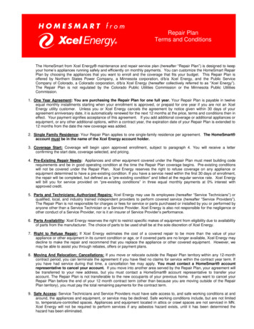
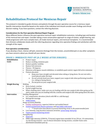
September 2016Section 2 SpecificationsSPECIFICATIONSTorque ProcedureSeal-LokTM fittingsa1 Replace the O-ring. The O-ring must bereplaced anytime the seal has been broken.The O-ring cannot be re-used if the fitting orhose end has been tightened beyond fingertight.bcFigure 1Note: The O-rings used in the Parker Seal Lok fittings and hose ends are custom-size O-rings.They are not standard SAE size O-rings. They areavailable in the O-ring field service kit (Genie partnumber 49612).2 Lubricate the O-ring before installation.3 Be sure that the face seal O-ring is seated andretained properly.4 Position the tube and nut squarely on the faceseal end of the fitting and tighten the nut fingertight.abchex nutreference markbody hex fitting3 Working clockwise on the body hex fitting,make a second mark with a permanent inkmarker to indicate the proper tighteningposition. Refer to Figure 2.Note: Use the JIC 37 Fittings table on theprevious page to determine the correct number offlats for the proper tightening position.Note: The marks indicate that the correcttightening positions have been determined. Usethe second mark on the body hex fitting to properlytighten the joint after it has been loosened.5 Tighten the nut or fitting to the appropriatetorque per given size as shown in the table.6 Operate all machine functions and inspect thehoses and fittings and related components toconfirm that there are no leaks.bacbJIC 37 fittingsFigure 21 Align the tube flare (hex nut) against the noseof the fitting body (body hex fitting) and tightenthe hex nut to the body hex fitting to hand-tight,approximately 30 in-lbs / 3.4 Nm.2 Make a reference mark on one of the flats ofthe hex nut, and continue it on to the body hexfitting with a permanent ink marker. Refer toFigure 1.Part No. 1272852abcbody hex fittingreference marksecond mark4 Tighten the hex nut until the mark on the hexnut is aligned with the second mark on the bodyhex fitting.5 Operate all machine functions and inspect thehoses and fittings and related components toconfirm that there are no leaks.GTH-55192-9
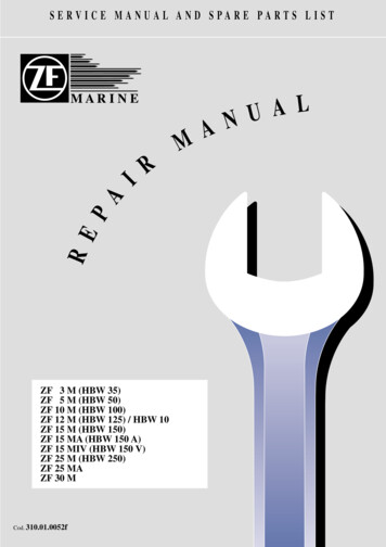
September 2016Section 2 SpecificationsSPECIFICATIONSSAE FASTENER TO RQ UE C HART This chartis to be used as a guide only unless noted elsew here in this m anual S IZEG rade 5TH READLUBED20281/4DRY5/163/87/161/29/165/83/47/811 1/81 1/41 01320121811181016914812712712612A 574 High StrengthBlack O xide BoltsLUBEDG rade 04067M ETRIC FASTENER TO RQ UE C HART This chartis to be used as a guide only unless noted elsew here in this m anual Class 4.6Size(m m 202224C lass 31420Nm19.137.866105170233330450570Class 269371525715909GTH-551912.9DRYin-lbsDRYft-lbsC lass 12.910.9Nm42.684.41472343655037139701233Part No. 1272852
September 2016Section 3 Repair ProceduresRepair ProceduresAbout This SectionMost of the procedures in this section should onlybe performed by a trained service professionalin a suitably equipped workshop. Select theappropriate repair procedure after troubleshootingthe problem.Observe and Obey:Perform disassembly procedures to the pointwhere repairs can be completed. Then to reassemble, perform the disassembly steps inreverse order.Repair procedures shall be completed by aperson trained and qualified on the repair ofthis machine.Immediately tag and remove from service adamaged or malfunctioning machine.Symbols LegendSafety alert symbol—used toalert personnel to potentialpersonal injury hazards. Obey allsafety messages that follow thissymbol to avoid possible injury ordeath.Repair any machine damage or malfunctionbefore operating the machine.Before Repairs Start:Read, understand and obey the safety rulesand operating instructions in the appropriateoperator’s manual on your machine.DANGERBe sure that all necessary tools and parts areavailable and ready for use.Indicates an imminentlyhazardous situation which, if notavoided, will result in death orserious injury.WARNING Indicates a potentially hazardousUse only Genie approved replacement parts.situation which, if not avoided,could result in death or seriousinjury.Read each procedure completely and adhereto the instructions. Attempting shortcuts mayproduce hazardous conditions.CAUTION Indicates a potentially hazardousUnless otherwise specified, perform each repairprocedure with the machine in the followingconfiguration:Machine parked on a firm, level surfaceBoom in the stowed positionKey switch in the off position with the keyremovedWheels chockedsituation which, if not avoided,may cause minor or moderateinjury.NOTICEIndicates a potentially hazardoussituation which, if not avoided,may result in property damage.Note: Used to indicate additional operation orprocedure information.Indicates that a specific result is expected afterperforming a series of steps.Indicates that an incorrect result has occurredafter performing a series of steps.Part No. 1272852GTH-55193-1
September 2016Section 3 Repair ProceduresBoom Components1-1BoomHow to Remove the LiftingFork Frame1 With the boom in the stowed position, attach alifting strap from an overhead crane to the topof the lifting fork frame at the front of the boom.Support the frame. Do not apply any liftingpressure.How to Replace theBoom Wear Pads1 Extend the boom until the wear pads areaccessible.2 Fork end of the boom - lower wear pads:Using a lifting strap from an overhead craneor a fork lift of sufficient capacity, lift the boomtube just enough to remove the weight from thepads.2 If the machine is equipped with the lifting forkframe locking cylinder, disconnect the lockingcylinder hoses from the boom.WARNING3 Pivot end of the boom - lower and upperwear pads: Use a prisebar to remove theweight of the boom inner section from the pads.Bodily injury hazard. Sprayinghydraulic oil can penetrate andburn skin. Loosen hydraulicconnections very slowly to allowthe oil pressure to dissipategradually. Do not allow oil tosquirt or spray.4 Remove the wear pad retainer plates andremove the wear pads from the boom.3 Remove the screw securing the fork levelcylinder pivot pin to the lifting fork.5 Lubricate the wear surface of the new pads.Refer to Maintenance Procedure A-4, Lubricatethe Boom.4 Use a soft metal drift to remove the pivot pin.Note: Do not lubricate the side wear pads.5 Remove the screw securing the fork framepivot pin to the boom.6 Use a soft metal drift to remove the pivot pin.6 Install the wear pads. Install and securelytighten the retainer plates. Do not over tighten.7 Using the overhead crane, lift and remove thefork frame from the boom.CAUTION Crushing hazard. The forkframe could fall if not properlysupported when the lock pin isremoved from the machine.3-2GTH-5519Part No. 1272852
September 2016Section 3 Repair ProceduresBOOM COMPONENTSHow to Remove the BoomWARNING8 Flip the slave cylinder towards the cab.Bodily injury hazard. Thisprocedure requires specificrepair skills, lifting equipmentand a suitable workshop.Attempting this procedurewithout these skills and toolscould result in death or seriousinjury and significant componentdamage. Dealer service isstrongly recommended.Note: When removing a hose assembly or fitting,the O-ring on the fitting and/or hose end must bereplaced and then torqued to specification duringinstallation. Refer to Section 2, Hydraulic Hoseand Fitting Torque Specifications.9 Using a soft metal drift, remove the lift cylinderlocking pin, boom side.10 Operate the 2 overhead cranes at the sametime to lower the boom being careful to rest thelift cylinder onto the support previously placedunderneath, and the boom tip onto anotherstand positioned to support the front part of theboom.11 Hook the 3 lifting points and then slowly lift theboom.12 Tag, disconnect and plug the hydraulic hosesthat go to the extend, retract, fork tilt and forkleveling cylinders, and the quick couplingcylinder (if equipped).WARNING1 Remove the forks from the boom.2 Disconnect the electric cables from the boom,if present.3 Lift the boom until the pin locking the liftcylinder is in a position above the cab roof.4 Place a stand under the lift cylinder to properlysupport it once the pin connecting the cylinderto the boom will be removed.13 Using a soft metal drift, remove the pinsecuring the boom to the machine.DANGER5 Attach a lifting strap from an overhead crane tothe fork support and slightly lift the boom. Donot apply any lifting pressure.6 Attach a second strap from the overhead craneto the lifting cylinder, rod side, and put sometension on it.Bodily injury hazard. Sprayinghydraulic oil can penetrate andburn skin. Loosen hydraulicconnections very slowly to allowthe oil pressure to dissipategradually. Do not allow oil tosquirt or spray.Crushing hazard. The boomwill fall if not properly supportedwhen the pivot pin is removedfrom the machine.14 Carefully remove the boom assembly from themachine and place it on a structure capable ofsupporting it.7 Using a soft metal drift, remove the slavecylinder locking pin from the boom support.DANGERCrushing hazard. The cylinderwill fall if not properly supportedwhen the pivot pin is removedfrom the machine.Part No. 1272852GTH-55193-3
September 2016Section 3 Repair ProceduresBOOM COMPONENTSHow to Disassemble the BoomBodily injury hazard. Thisprocedure requires specificrepair skills, lifting equipmentand a suitable workshop.Attempting this procedurewithout these skills and toolscould result in death or seriousinjury and significant componentdamage. Dealer service isstrongly recommended.WARNINGNote: When removing a hose assembly or fitting,the O-ring on the fitting and/or hose end must bereplaced and then torqued to specificati
1. Service and Repair Manual GTH-5519 (Deutz Tier 4i) From GTH5514B-101 to GTH5516B-4410 From GTH5516M-4