Transcription
PRECASTCONCRETEMANHOLES
WHY PROVIDE GUIDELINES?Past Problems Was tedious to keep track ofvariables Was easy to make mistakes Wanted: A design tool to reduceproblems
TOPICS Overview on Precast Manholes Applications Design Procedures andApplicable Standards Watertight Structures Quality Installation
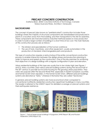
PRECAST CONCRETE MANHOLESRound Structures ASTM C478, “StandardSpecification for PrecastReinforced ConcreteManhole Sections”
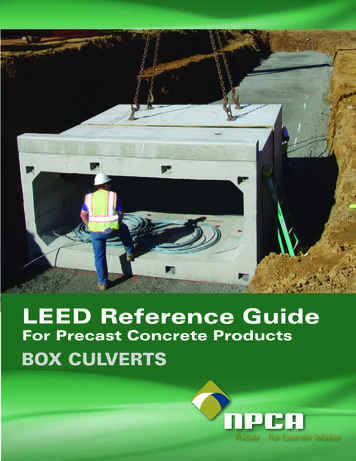
PRECAST CONCRETE MANHOLESRectangle / Square Structures ASTM C913, “StandardSpecification for Precast ConcreteWater and Wastewater Structures” DO NOT Specify a Box Culvertfor a vertical application. BoxCulverts are designed forhorizontal installations andloading conditions. Specify ASTM C913 for squarestructures.
COMMON SIZESRound – ASTM C478 Internal Diameter (I.D.) 36” – 144” Check with localmanufacturer foravailability of largerdiameter structures.Custom box structuresare easily fabricatedusing universal formingequipment.
COMMON SIZESRectangle / SquareASTM C913 24” x 24” to 72” x 72” sizes increase by 6”increments
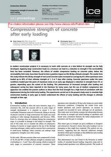
MANUFACTURING METHODSWet-Cast Cast with an inner and outer form. Product cured in the form. Blockouts/hole formers can easily be incorporated.
MANUFACTURING METHODSWet-Cast Cast with conventional concrete or self-consolidatingconcrete. Base sections are typically wet-cast. Wet-cast is common for sanitary applications.
MANUFACTURING METHODSDry-Cast (Machine Made) Product is cast utilizing mechanized equipment. Form vibrators consolidate zero-slump concretebetween core and jacket.Manufacturing Methods The product is immediately stripped and the form isreused. Products typically cured in a kiln or a combination oftarps and moisture curing is used.
MANUFACTURING METHODSDry-Cast (Machine Made) Both round and square structures may be dry-cast. Hole formers may be incorporated, or coring is doneas needed.Manufacturing Methods Surface may appear rough due to manufacturingprocess.
PRECAST ADVANTAGES Readily Available (more than 400 NPCA members supply precast concrete manholes) Modular Flexible Design May be designed to accommodate existing utilities Produced in a Quality Controlled Plant Environment
PRECAST ADVANTAGES Watertight Structures Easily Achieved Resists Buoyant Forces Superior Strength
APPLICATIONSSanitary and Stormwater Sewer Provide access for inspection and maintenance. Monolithic drop manholes available.Stormwater Inlet and Treatment Structures Structure for housing stormwater treatment equipment. Various proprietary treatment systems available.
APPLICATIONSPump/Lift Stations Sanitary andstormwater sewerapplications. Accommodate elevationchanges in gravity flowsewer systems.
APPLICATIONSUtility Manholes Provide access tounderground utilitiesand/or vaults. Used by electrical,telecommunications, fiberoptics, water and gascompanies. May be referred to as avalve vault.
DESIGN StructureSizing Round Structures ASTM C478 ASTM C497 Rectangle/Square Structures ASTM C913 ASTM C890 Lifting and Handling Corrosion Mitigation
SIZING CONSIDERATIONS The structure (round or square) must be large enough toaccept the maximum size pipe. The structure size is a function of the number, size,elevation and entry angle of pipes connecting to thestructure. The structural integrity must be maintained by providing aminimum structural leg of concrete between pipe holes. Ageneral rule of thumb is to provide a minimum of 6 inchesas measured from the interior of the structure.
SIZING CONSIDERATIONS The type of pipe entering the structure and accompanyingconnection method (boot, compression or mortar) must beknown to accurately determine the required hole size andstructure size. Transition sections may be incorporated above a largerbase section to utilize smaller riser sections, which mayminimize overall project costs.
SIZING CONSIDERATIONS Square and/or rectangular structures are typically usedwhere pipes can intercept at 90 degrees or 180 degrees.Most roadways and some stormwater site drainage systemsemploy these types of structures. Round structures allow more flexibility in the system designand layout. Various sizes of pipes entering at differentangles can more easily be accommodated by a roundstructure, ensuring watertight connections are maintained.
SIZING CONSIDERATIONS When possible, avoid pipes entering into structure joints andcorners, as this may compromise the structural integrity andwatertightness of the structure. However, this practice maybe necessary for certain installations and should be left tothe discretion of an experienced precast concretemanufacturer. Consult your local precast concrete manufacturer andconnector supplier for exact design requirements andproduct specifications.
SIZING CONSIDERATIONSHole Sizing for Reinforced Concrete Pipe (ASTM C76)Relationships between Inside Diameter(I.D.), Wall Thickness (W.T.), OutsideDiameter (O.D.) and Hole Size (H.S.)* forconcrete pipe.W.T. (in inches) I.D./12 1O.D. I.D. (W.T. x 2)H.S. O.D. (2” to 4”)* H.S. may vary depending on type of pipeand connection used. H.S. diameter maybe 2-4 inches larger than O.D.Example: ? Hole Size for 24” RCPW.T. 24/12 1 3”O.D. 24 (3 x 2) 30”Hole Size (H.S.) 30 4 34”O.D. 30”W.T. 3”I.D. 24”H.S. 34”
SIZING CONSIDERATIONSMinimum Dimensions For Structures Local specifications and designhandbooks may include minimumrequirements and design tables toassist in the sizing of manholestructures. The adjacent table addressesstructure sizing when usingconcrete pipe for storm drains.RectangularRoundSide DimensionDiameter30 in.3 -6”4 ft.36 in.4 ft.5 ft.42 in.5 ft.6 ft.48 in.6 ft.6 ft.54 in.6 ft.8 ft.60 in.7 ft.8 ft66 in.7 ft.8 ft72 in.8 ft.8 ft78 in.9 ft.10 ft.PipeSizeTable 4-2Florida DOT Drainage Handbook: StormDrains (January 2004)
SIZING CONSIDERATIONSMinimum Angle Between Pipes Entering RoundStructures Pipe opening (H.S.) is assumedto be: H.S. I.D. W.T. (2” to 4”) Recommended minimumstructural leg is 6 inches asmeasured from the interior of thestructure. Structure #1 would not providethe minimum structural leg. Increasing the manhole diameterto the next size (Structure #2)provides the required structuralleg.
SIZING CONSIDERATIONS Required minimum structural leghas not been achieved. A larger diameter manhole baseshould have been specified. Authorities havingjurisdiction may require aminimum amount of concreteabove openings.
SIZING CONSIDERATIONSSkewed pipes entering rectangularstructures Watertight connections may be difficult to achieve. Typically done in stormwater structures using mortarjoints. Consider the use of a round structure and flexibleconnector when requiring a watertight structure.
SIZING CONSIDERATIONSSkewed pipes entering rectangularstructures Authorities having jurisdiction may provide design tablesaddressing pipe size and maximum allowable skew angles.Table 4-3 Florida DOT Drainage Handbook: Storm Drains (January 2004)Pipe ��19o17o16o16o15o14o14o13oThese values are based on 2" of construction tolerance, precaststructures with 8" walls, and concrete pipe dimensions.
SIZING CONSIDERATIONSTransition Slabs Allow the use of a larger basesection to accommodate pipesizes and entry angles. Provides transition to smallersize riser sections.
SIZING CONSIDERATIONSTransition Slabs Slabs must be designed properlyto withstand the anticipatedloads (riser sections, backfilledsoil, surcharge loads, etc.).
DESIGN Structure Sizing Round Structures ASTM C478 ASTM C497 Rectangle/Square Structures ASTM C913 ASTM C890 Lifting and Handling Corrosion Mitigation
ROUND STRUCTURESMaximum DepthASTM C478 and ASTM C497Products Grade RingsFlat Slab TopsRisers and Conical TopsBase SectionsSteps and Ladders
ROUND STRUCTURESMaximum DepthASTM C478 and ASTM C497Reinforcement Options Conventional Reinforcing SteelWelded Wire ReinforcementHoop Steel ReinforcementFiber Reinforcement
ROUND STRUCTURES According to the American Concrete PipeAssociation (ACPA), the maximum allowabledepth of a typical precast concrete roundmanhole is in excess of 500 feet. Let’s check that statement for riser sectionswith no openings.
ROUND STRUCTURESAssume the water table is at the same elevationas the ground surface.Forces Acting on the Manhole Structure Include: Lateral Earth Pressure Hydrostatic Pressure
ROUND STRUCTURESBecause both loads are uniformly distributed around theperiphery of the manhole, no bending moment is experiencedby the manhole section. The following equation may be usedto calculate the total lateral pressure at a given depth (H):Where:p total lateral earth and hydrostatic pressure (pounds per square foot)ws effective unit weight of the backfill materials (pounds per cubic foot)H depth of manhole (feet)Ks conjugate ratio for soili angle between backfill surface and the horizontal (degrees)ww unit weight of water (62.4 pounds per cubic foot)Kw conjugate ratio for water (1.0)
ROUND STRUCTURES Most backfill top surfaces are flat and “i” typically equals 0;therefore, cos(i) 1. Using a common angle of internal friction of 30 degrees forthe backfill material, Ks simplifies to 1/3. Assuming the saturated unit weight of the backfill materialequals 120 pounds per cubic foot, the effective unit weightwould be 120 – 62.4 57.6 pounds per cubic foot. Using the above information, the equation simplifies to thefollowing:
ROUND STRUCTURESIn theory the pressure (p) acts equally around the periphery of the round manholesection, placing the ring in pure compression without introducing bending momentsinto the concrete section in the horizontal plane. The compressive stress in anysection of the round manhole riser is given by the equation:Where:s unit compressive stress in the ring (pounds per square foot)p total lateral earth and hydrostatic pressure (pounds per square foot)D diameter of the manhole (feet)t thickness of the manhole wall (feet)t must be a minimum of 1/12 the largest diameter riser section.
ROUND STRUCTURESSubstituting the known values into the above equationsyields the following:81.6 H Ds 1144 2 D12thens 3.4 H
ROUND STRUCTURESs 3.4 HWhere:s unit compressive stress in the ring (pounds per square foot)H depth of manhole, feetUsing an allowable concrete stress of 45% of the minimum specifiedcompressive strength of 4,000 psi, the allowable compressive stresswould be 1,800 psi. Substituting this value for s yields the following:1,800 3.4Hthen H 530 feetThe above example illustrates that precast concrete manholesections may be installed to considerable depths. However, ensurethe base sections and/or transition slabs are properly designed towithstand the anticipated loads.
ASTM C478: ROUND STRUCTURESStandard Specification for Precast ConcreteManhole Sections ASTM C478 covers the manufacture and purchaserequirements of products used for the assembly andconstruction of circular precast reinforced concretemanholes used in sewer and water works. The standard is divided into two parts. Part I covers general requirements on materials, design,reinforcement, manufacturing, acceptance, repair,inspection and product marking.
ASTM C478: ROUND STRUCTURESStandard Specification for Precast ConcreteManhole Sections Part II covers the minimum requirements for the variousmanhole components. The following products are addressed: grade rings, flatslab tops, risers/conical tops, base sections andsteps/ladders. It should be noted that ASTM Standards are minimumdesign specifications.
ASTM C478: OVERVIEW PART IThe concrete constituents shall conform to theapplicable ASTM Standards. Cement – ASTM C150, Aggregates – ASTM C33, etc.Minimum compressive strength shall be 4,000 psi. Maximum water-cementitious ratio of 0.53 specified. A typical precast wet-cast mix has a w/c ratio of 0.38 – 0.45. A typical precast dry-cast mix has a w/c ratio of 0.24 – 0.30.
ASTM C478: OVERVIEW PART IAbsorption Test Requirements as outlined in ASTM C497. Test Method A: Max 9% (specimen shall have maxweight of 0.22 lb.) Test Method B: Max 8.5%Repairs to product are allowed.
ASTM C478: OVERVIEW PART IProducts shall be marked w/ ASTM designation,date manufactured and manufacturer’s name orlogo.Reinforcement options will be covered in thefollowing slides.
REINFORCEMENTConventional Reinforcing Steel Typically used in base slabs and flatslab tops. Additional bars may be placed aroundblockouts. Conforms to ASTM A615. Although not included in ASTM C478,plants may use ASTM A706 reinforcingsteel when welding reinforcing mats.
REINFORCEMENTWelded Wire Reinforcing (WWR) Steel Commonly used for reinforcing risers and conicalsections. Available in prefabricated rolls with varying spacing andsteel area per foot. Plain WWR - ASTM A185 Deformed WWR - ASTM A497 Cages may be manufactured at the plant withmechanized equipment using steel wire. Plain Wire - ASTM A82 Deformed Wire - ASTM A496
REINFORCEMENTHoop Steel Reinforcement Not allowed for reinforcing base sections. Allowed for reinforcing risers and conical tops up to 48inches in height and 48 inches in diameter. Welded splices shall have a min. lap of 2 inches and shalldevelop 50% of the minimum specified strength of thesteel. Butt welded splices shall develop at least 75% of theminimum specified strength of the steel. Continuity of steel should be maintained.
REINFORCEMENTSecondary Synthetic Fibers Fiber reinforcement shall not be used to replace primaryreinforcing steel. Allowed for use in steel reinforced manholes assecondary reinforcement. Helps minimize handling damage (chips and spalls). Only fibers designed and manufactured specifically foruse in concrete and so certified by the manufacturer shallbe accepted.
ASTM C478: OVERVIEW PART IIPart II covers the specificrequirements for the variousproducts used to construct aprecast concrete manhole system.Products: Grade Rings Flat Slab Tops Risers and Conical Tops Base Sections Steps and Ladders
ASTM C478: OVERVIEW PART IIRequirements covered in eachproduct section: Design Joints Reinforcement
GRADE RINGS Precast concrete grade rings are used forfinal adjustment of manholes to grade andavailable in a range of heights anddiameters. Grade rings are often supplied in bulk orby the pallet. Grade rings are not required to have a male/female joint. The minimum wall thickness is 1/12 of the internaldiameter of the grade ring or 4 inches, whichever isgreater.
GRADE RINGSCircumferential ReinforcementRequirements Minimum steel area of 0.07 squareinches per vertical foot, but not lessthan 0.024 square inches in any onegrade ring. A minimum of inch of concretecover must be provided.
FLAT SLAB TOPSFlat slab tops are often used to provide a transition from alarger diameter base to a smaller diameter riser section.Design Flat slab tops must be designed to withstand theanticipated loads from supported riser sections, soiland hydrostatic loads, surcharge loads, live loads andimpact loads. Tops shall be designed in accordance with ACI 318. Acceptance on the basis of Proof-of-Design testing asoutlined in ASTM C497.
FLAT SLAB TOPSDesign Slab Thickness: For risers 48 inches in diameter and smaller,minimum of 6 inches. For risers larger than 48 inches in diameter,minimum of 8 inches. Access opening shall be a minimum of 24 inches indiameter. Joints may or may not be designed with a male orfemale end. Shear load testing of joints is not required.
FLAT SLAB TOPSReinforcement Requirements Tops with a joint or with other indication of a top andbottom side shall have one layer of steel reinforcementplaced near the bottom surface so that the protectivecover over the reinforcement is 1 inch. Tops without a joint or without other indication of a topand bottom side shall have two layers of steelreinforcement, one located near the bottom surface andone near the top surface so that the protective coverover each layer is 1 inch.
FLAT SLAB TOPSReinforcement Requirements The minimum area of reinforcing steel is 0.12 squareinches per linear foot in both directions Additional reinforcing steel is required aroundopenings: A minimum of 0.20 square inches of steel at 90degrees and the length of the reinforcing must begreater than the diameter of the opening plus 2inches.
FLAT SLAB TOPSReinforcement Requirements Required concrete cover: A minimum of inch is required. 1 inch required above and/or below baseslab reinforcement.
RISERS and CONICAL TOPSPrecast concrete manufacturers typically stock a variety ofriser sections and conical tops. Conical tops are oftenreferred to as cones and are available in both concentricand eccentric designs.DesignMinimum Wall Thickness 1/12 of the largest internal diameter of the riser orconical top.
RISERS and CONICAL TOPSDesignCircumferential Reinforcing Steel Shall consist of one or two lines of steel.* The total area of circumferential reinforcing steel pervertical foot shall be not less than 0.0025 times theinternal diameter of the section, in inches. Example: minimum circumferential reinforcing steel for a48-inch-diameter manhole is 48 x 0.0025 0.12 in2*See ASTM C478 for requirements when two lines of steel are used.
RISERS and CONICAL TOPSDesignCircumferential Reinforcing Steel Steel shall be placed in the center third of the wall. A minimum of inch concrete cover is required. The spacing center to center of circumferentialreinforcement in a cage shall not exceed 6 inches.
RISERS and CONICAL TOPSDesignSteel Hoop Reinforcement Risers and conical tops 24 inches in height No fewer than two hoops of steel wire or reinforcingbars. Must have a minimum cross-sectional diameter of0.250 inches. Must be located in each end quarter of the sectionand be a minimum of 1 inch from the shoulder ofthe section.
RISERS and CONICAL TOPSSteel Hoop ReinforcementRisers and conical tops 24 inches and 48 inches in height No less than three hoops of steel wire or reinforcingbars. Must have a minimum cross-sectional diameter of 0.250inches. One hoop must be located in each end quarter of thesection and be a minimum of 1 inch from the shoulder ofthe section. The third or middle hoop shall be located in the middle ofthe section as measured from the shoulder, /- 6 inches.
RISERS and CONICAL TOPSSteel Hoop ReinforcementHoop steel location and cover Placed in the middle third of the wall. A minimum of inch of concrete cover must beprovided.
RISERS and CONICAL TOPSJoints Sections shall be designed andmanufactured with male andfemale ends. The tongue and groove of the jointare not required to containcircumferential reinforcement. Joint sealants will be covered inthe watertightness section.
BASE SECTIONSThere are three different methods for fabricating precastconcrete base sections: The riser wall and base slab may be castmonolithically. Such sections are often cast upsidedown and flipped the following day during thestripping process. A base may be cast utilizing a previously cast risersection with a secondary poured base slab, with orwithout benching. A separate precast concrete base slab and risersection may be cast and sealed with a male/femalejoint between the two pieces.
BASE SECTIONSDesignSlab Thickness For bases 48 inches in diameter and smaller: minimumof 6 inches. For bases larger than 48 inches in diameter: minimumof 8 inches.Slab Thickness: Monolithically Cast Base with Bench Inverts Minimum concrete thickness from the invert to bottom ofthe base slab shall be 4 inches.
BASE SECTIONSDesignBenched Inverts The slope shall be a minimum of inch per foot from thechannel to the inside diameter (ID) of the riser wall for thebenching. Channel invert depth shall be a minimum of one-half thepipe ID. Secondary poured channels shall have a minimumthickness under the invert of 2 inches. The width of the channel at the top of benching shall be ata minimum equal to the pipe ID.
BASE SECTIONSDesignBenched Inverts Minimum channel centerline radius shall be equal tothe pipe ID.Reinforcement The base riser section shall conform to the samereinforcement requirements for risers and conicaltops.Base Slab Reinforcement A minimum of 0.12 square inches per linear foot inboth directions.
BASE SECTIONSDesignBase Slab Reinforcement (cont.) Shall be placed above the midpoint of the base slab. A minimum of 1 inch concrete cover shall bemaintained. Joints are not required to contain reinforcing steel.
STEPS and LADDERS Steps and ladders provide a means ofingress for precast concrete manholestructures. They may be cast,mortared or attached by mechanicalmeans to the manhole components. Manhole steps and ladders shallconform to the requirements of theOccupational Safety and HealthStandards, U.S. Department of Labor.
STEPS and LADDERSStep designs are required to be tested inaccordance with ASTM C497: Horizontal pullout load shall be 400 Vertical load shall be 800 lb. Spacing of steps shall be limited to a maximumdistance of 16 inches.
ASTM C497Standard Test Methods for Concrete Pipe,Manhole Sections and Tile ASTM C497 addresses various testmethods used during production andacceptance of concrete pipe, manholesections and tile. AHJ may require one or more of thesetests to be performed on a routine basisor that the manufacturer maintain currenttest result documentation.
ASTM C497The following test methods pertain totesting procedures for precast manholes: Flat Slab Top Test Method Absorption Test Method Hydrostatic Test Method Manhole Step Test Methods Cylinder Strength Test Method(casting dry-cast compression specimens)
DESIGNStructure SizingRound Structures ASTM C478 ASTM C497Rectangle/Square Structures ASTM C913 ASTM C890 Lifting and Handling Corrosion Mitigation
RECTANGULAR / SQUARESTRUCTURESASTM C890, Standard Practice for Minimum StructuralDesign Loading for Monolithic or Sectional PrecastConcrete Water and Wastewater Structures ASTM C890 addresses the minimum loads to beapplied when designing monolithic or sectionalprecast concrete water and wastewater structures. ASTM C890 does not address: Concrete Pipe Box Culverts Utility Structures Manholes (ASTM C478)
RECTANGULAR / SQUARESTRUCTURESASTM C913, Standard Specification for Precast ConcreteWater and Wastewater Structures ASTM C913 covers the recommended designrequirements and manufacturing practices formonolithic or sectional precast concrete water andwastewater structures, excluding the previouslymentioned products.
DESIGN LOADSDead LoadsPermanent vertical loads to consider: Roads Walkways Earth backfill Access opening covers
DESIGN LOADSWeights of common materialsTable 1 Unit Weights of Materials (ASTM C890)Weight, lb/ft3MaterialConcrete (plain or reinforced)150Lightweight concrete (reinforced)100 to 130Cast Iron450Steel490Aluminum175Earth Fill100 to 150Macadam140
DESIGN LOADSTraffic Loads Vehicle and Pedestrian loads are provided inTable 2 of ASTM C890. Table 2 corresponds to the AASHTO loaddesignations (i.e., HS20-44). Wheel load distribution area.Above ground structuresA W x L
DESIGN LOADSTraffic LoadsBelow ground structuresA (W 1.75H) x (L 1.75H)Where:A wheel load area (ft2)W wheel width, ftL wheel length, ftH height backfill betweenwheels and structure, ftTable 2 Wheel Load Increases for Impact (ASTM C890)Height of Backfill Between Wheel and StructureIncrease0 to 12 in.30%13 to 24 in.20%25 to 35 in.10%36 in or greater0%
DESIGN LOADSHydrostatic Loads Water pressure acting on both the interior and exterior of thestructure must be taken into consideration.Lateral Earth Loads Ground water levels must be known. Backfill soil properties must be known: Unit weight of the earth backfill. Internal friction angle of earth backfill. Pressure on walls of buried structures should be calculatedusing the equations provided in ASTM C890. Structures must be designed for all possible loadingconditions.
DESIGN LOADSSurcharge Loads When traffic can come within a horizontal distance fromthe structure equal to one half of the height of thestructure, a lateral surcharge pressure will be applied tothe wall of the structure. Water pressure acting on boththe interior and exterior of the structure must be takeninto consideration. Lateral surcharge pressures for corresponding vehicleload designations are provided in Table 4 of ASTMC890.
DESIGN LOADSSurcharge Loads Lateral surcharge loads from traffic are considerednegligible past a vertical distance of 8 ft below thewheel.Other loads to consider Snow and ice loads when applicable (use local buildingcodes). Pedestrian live loads (above ground structures). Lifting loads. Buoyancy should be checked.
ASTM C913: OVERVIEWConcrete Constituents shall conform to the applicable ASTMStandards. Air Entrainment is required when there is a potential forfreeze/thaw. 5.5 /- 1.5% air by volume as measured by ASTM C231. Minimum compressive strength of 4,000 psi at 28 days.
ASTM C913: OVERVIEWReinforcement Wire: A82 or A496 Wire Fabric: A185 or A497 Prestressed Wire and Strand: A416 or A421 Bars: A184, A615, A616 or A617 Minimum Concrete cover Water retaining structures: 1 inch Other structures: inchDesign In accordance with ACI 318 and ASTM C890. Performance test (Proof-of-Design) is subject to approval ofthe customer.
ASTM C913: APPENDIXESThe appendixes of ASTM C913 provides designs for standardsized box structures as a convenience for specifying,purchasing and manufacturing.Structural Analysis Analysis based on slope-deflection solution of a framewith nonprismatic members. Loads are based on ASTM C890.Design Calculations Concrete strength of f’c 4,000 psi. Reinforcing steel shall be Grade 60. Wall thickness is 6 inches.
ASTM C913: APPENDIXESDesign Calculations ACI 318 strength design method is used with U.L.F. 1.7. Minimum reinforcement is 0.002 times the gross concretearea of the section. Standard designs provided for 2 ft by 2 ft structures up to6 ft by 6 ft. Dimensions increase by foot in either direction. If the calculated loads are greater than those provided inthe table, an engineer should be engaged to provide thedesign.
DESIGNStructure SizingRound Structures ASTM C478 ASTM C497Rectangle/Square Structures ASTM C913 ASTM C890Lifting and HandlingCorrosion Mitigation
LIFTING and HANDLING DEVICESLifting devices should bedesigned with a minimumsafety factor of 4.There are a number ofproprietary devices availablefor lifting and handling precastconcrete products.Bent reinforcing steel barsshould not be used as liftingdevices.
LIFTING and HANDLING DEVICESPlant-manufactured liftingdevices are often fabricatedfrom smooth bars or braidedcables.Plant-manufactured liftingdevice designs should beevaluated by a ProfessionalEngineer, or proof of designtesting should be performedand documented using a safetyfactor of 4.
CORROSION MITIGATIONPrecast Concrete Manholes may be subjected tovarious corrosive environments.Sanitary Sewer Applications The formation of hydrogen sulfide (H2S) gas mayincrease the potential for Microbial Induced Corrosion(MIC). The release of H2S can be controlled by proper hydraulicdesign of the sanitary sewer system. Consult the ACPA Design Manual, “Sulfide andCorrosion Prediction and Control,” for additionalinformation.
CORROSION MITIGATIONPrecast Concrete Manholes may be subjected to variouscorrosive environments.Light Industrial Applications Chemicals and solvents with varying pH levels may havean adverse effect on concrete. It is important to know as much information on theintended use of the products so appropriate corrosionmitigation methods may be selected.
CORROSION MITIGATIONCast-in linersmay be used tocombat theeffects ofcorrosive agents.Coatings on boththe interiorand/or exteriormay be specified.
CORROSION MITIGATIONMix designs can be adjusted to improve the durability ofthe concrete. Use a low water-to-cementitious ratio Incorporate supplementary cementitious materials.Corrosion Mitigation Admixtures Various admixtures available on the market. ASTM Subcommittee C13.03 is developing a standardtest method to verify the performance of the admixtures. The test method is currently in developmental stage.
WATERTIGHTNESSWatertight joints and connections should be specified forprecast concrete manhole structures used for sanitary andstorm sewer applications.Why? 80% of drinking water comes from ground water. Exfiltration from both sanitary and stormwater sewersmay contaminate local ground water supplies. Yes, stormwater contains a number of pollutants,especially during the initial flush, which occurs shortlyafter the start of a heavy storm.
WATERTIGHTNESS Infiltration of water into a sewer may exceed the system’sdesign capacity. Infiltration from contaminated soils increases theconcentration of pollutants in a stormwater sewer system,which may flow directly into a local lake or stream. Infiltrating water may erode surrounding backfill material,increasing the potential for sinkholes. Increased suspended solids and pollutants will disruptsensitive ecosystems.
WATERTIGHTNESS: MORTAR Mortar joints and connections do notensure a watertight system. The quality of the mortar installationvaries considerably in the field. Breaches to watertightness increasethe chances for groundwatercontamination and the erosion ofsurrounding backfill materials.
WATERTIGHTNESS: JOINTSASTM C990, “Standard Specification for Joints forConcrete Pipe, Manholes, and Precast Box SectionsUsing Preformed Flexible Jo
Was tedious to keep track of variables Was easy to make mistakes Wanted: A design tool to reduce problems. TOPICS Overview on Precast Manholes Applications Design Procedures and Applicable St