Transcription
INSPECTIONOFFIELD WELDING
ObjectiveTypes of Projects Involving Welding Common Welding Terms & Symbols Welder Qualifications Common Welding Requirements Welding Inspection
Types of Projects Involving FieldWelding New Structures: Bridge Rail Strip Seal Extrusions / Armor Angles Pile-to-Girder Connections Pile splice
Types of Projects Involving FieldWelding Rehabilitation Projects Bridge Rail Strip Seal Extrusions / Armor Angles Fatigue Retrofits Weld Repairs
Common Field Weld Types Fillet Welds Groove WeldsSquare Groove WeldFillet WeldV - Groove Weld
Symbols for Fillet Welds When symbol is belowthe line, the weld is tobe placed on the sideto which the arrowpoints
Symbols for Fillet Welds When the symbol isabove the line, the weldis to be placed on theopposite side of thejoint to which the arrowis pointing.
Symbols for Fillet Welds Weld symbols bothsides of the lineindicate that the weld isto be placed on bothsides of the joint.
Symbols for Groove Welds Arrow SideOpposite SideBoth SidesTypical Groove WeldSymbols
Additional Weld MarkingsField WeldWeld All AroundTail on end of weld iswhere any specialinstruction are placed
Surface Contours of WeldsIt may be specified that the weld surface of agroove weld have a certain contour:Weld Flush WithoutGGrindingGrind to ConvexGGrind to Flush
Welding PositionsFlatPositionHorizontalPosition
Welding PositionsVerticalPositionOverheadPosition
Welding PositionsSide ViewSide ViewEnd View
Welding PositionsSide ViewEnd View
Welding PositionsSide ViewEnd View
Welding PositionsSide ViewEnd View
Welder Certification 2004 StandardSpecifications Requirethat a Welder beCertified in TestPosition 3G (Vertical)for Unlimited ThicknessGroove Welds.
Welders Wanting to be CertifiedNeed to: Tested in accordance withANSI/AASHTO/AWS D1.5 Bridge WeldingCode to at least 3G (vertical up) Qualification to ANSI/AWS D1.1 StructuralWelding Code is NOT Acceptable.(Refer to Section 410.3.H)
Welders Wanting to be CertifiedNeed to: Welder Qualification needs to be performedunder the supervision of an AWS CertifiedWelding Inspector (CWI) and certified inaccordance with AWS QC1. Testing Firms Vo-Tech Schools
Welding ElectrodesField welding is done with a coveredelectrode (Stick Electrode) SMAW (Shielded Metal Arc Welding) Metal wire with a protective covering Current is passed through the electrode.–This causes metals to melt and fusetogether.
Welding Electrodes Only “Low HydrogenElectrodes” shall be used. E7016 E7018 Most Common E7028Approved List or Certificateof Compliance. Electrodes exposed to theatmosphere will absorbmoisture, therefore: Electrodes in unopenedoriginal containers may beused directly from container. Electrodes not used within 4hours or brought to the job inopen containers must bedried.
Drying Electrodes Electrodes not used with 4 hours or fromopen containers shall be dried as follows: E7018 2 hrs. @ 450 F to 500 FAfter drying, store in storage ovens @ 250 FReject Electrodes that have been wet.
Weather and Temperature Steel Must be preheated Welds shall not be placed whenthere is rain rain or snow Preheat will remove any wateron cold days
Preheat For A36 and A709 Gr. 36 & Gr.50:PLATETHICKNESSMIN. INTERPASSANDPREHEAT TEMP F3/4” or Less 3/4” thru 1 1/2” 1 1/2” thru 2 1/2”Over 2 1/2”5070150225
Preheat Carefully Review Plans/Shop Plans for OtherPreheat Conditions. Other Types of Steels May Require HigherPreheat. High Restraint Details May Require HigherPreheat.
Preheat Methods of Monitoring Preheat Surface Thermometer Thermomelt Stick– Thermomelt Sticks are made for severaldifferent temperatures.– Make sure proper stick is used.
Fillet Welds
Preparation of Base Metal Weld Connection Area Must be Free ofDefects and be Cleaned 2” Each Sideof Weld: No loose mill scale, rust, oil, or grease Galvanizing / Paint Removed Moisture Free
Fit-Up of Plates With Fillet Welds Proper Fit-up and Weld Size Plate separations of 1/16” to 3/16” requireleg of weld to be increased by the amountof seperation.
Fit-Up of Plates With Fillet Welds Separations of More than 3/16” Should Notbe Allowed. Contractor must correct
Alignment of Plates Plates Welded With Fillet or Groove WeldsNeed to be Held in Proper Alignment. Erection Bolts Tack Welds Clamps, Jacks, etc.
General Field Welding ProceduresUse Flat Welding Position if Possible Vertical Welds from Bottom Up Remove Slag Between Passes Chipping Hammer Wire Brush Arc Must be Struck in Immediate Weld Area
Inspection of Field WeldsMost Field Welding is in Low Stress Areas. Visual Inspection Welds in High Stress Areas are Much MoreCritical: Visual Inspection Non-Destructive Testing
Visual Inspection Groove Welds Weld Reinforcement of 1/32” to 1/8”– Except when a “Flush” weld is specified.Reinforcement
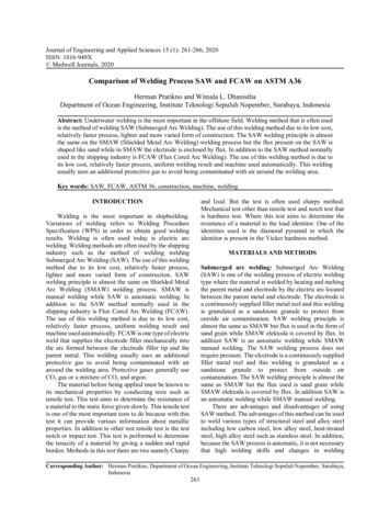
Visual Inspection Fillet Welds - Proper Size Concave Convex Near Flat Preferred
Fillet Weld GaugeSizeConcaveSideConvex SideType of Gauge Used By Department of Transportation
Concave Fillet Weld Effective Size of Concave Fillet Weld Shouldbe at Least the Weld Size Specified.
Concave Fillet Weld Weld Size Measured With Fillet Gauge
Convex Fillet Weld Weld Size Measured With Fillet Gauge
Weld Defects Types of Weld Defects: Undercut Overlap Porosity Cracks Spatter
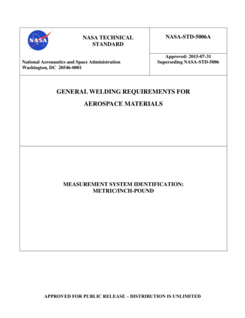
Undercut Undercut:Causes: Excessive Current Too Rapid of Welding Speed Excessive Manipulation ofElectrode Electrode at Wrong AngleReduction in Base MetalThickness Alongside Weld Correction: Add Weld Metal at undercut.
Undercut
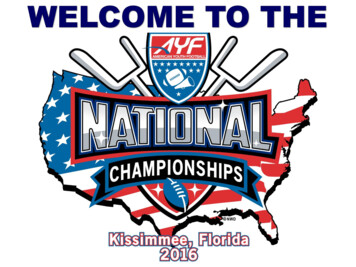
OverlapOverlap: Incorrect Current Too Slow Welding Speed Electrode at Wrong AngleOverflow Onto Base MetalWithout Fusion. OverlapCauses:Correction: Remove Excess or DefectiveWeld Metal– Grinder– Air Carbon Arc Re-Weld to Correct Size
Overlap
Porosity Porosity:Causes: Excessive Moisture Low Welding Current Improper Arc LengthCavities Caused by TrappedGases. Correction: Remove Defective Weld– Grinding– Air Carbon Arc Re-Weld to Proper Size
CracksCracks: Causes: Shrinkage of Weld Metal andResistance to Movement ofJoined Parts. Excessive Current WithRapid Cooling. Low Air Temperature.Separation in Weld Metal orAdjacent Base Metal.“All Cracks Must Be Repaired” Correction: Remove Defective Weld Re-Weld
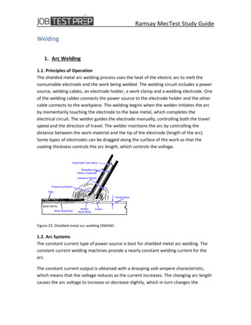
Spatter Spatter:Small Pieces of MetalScattered Over Weld Surfaceand Base MetalCauses: Excessive Current Improper Arc Correction: Remove Spatter With WireBrush and/or ChippingHammer
Spatter
Seal Weld Occasionally Used to Seal Out Moisture Not a Structural Weld Should be Visually Inspected
SaftyDo not watch the welding with out a weldinghelmet Do not touch the red hot stuff
Welding Electrodes Field welding is done with a covered electrode (Stick Electrode) SMAW (Shielded Metal Arc Welding) Metal wire with a protective covering Current is passed through the e