Transcription
WITH USER’S MANUALFebruary 2020
CopyrightNext Wave AutomationAll Rights Reserved.Ready2Control and Virtual Zero Unlimitedare registered trademarks of Next Wave Automation.Software copyright by Next Wave Automation. All rights reserved.All other trademarks are the property of their respective owners.Information in this manual is subject to change without notice.This manual is periodically updated.New versions (when available) can be downloadedfrom Help menu in the software.2Ready2Control User’s Manual
Table of ContentsPageTo Our Customers . . 4Software Warranty . . . . 4System Requirements . . . . . . 4Technical Support . . . . 5Safety . . 5START HERE:1.2.3.4.5.Overview (READ FIRST) . . . . . .Machine Registration . . . . First time Software Installation . . . . Connecting your CNC machine . . . . Firmware Updates . . . Software Updates . . . 6713192034Software OverviewMain Window . . . Menu Bar . . Update Icons . . . Job List Panel . . Viewport . Machine Controls . . Keypad Disabled view . Keypad Enabled View . . How to Zero Z with Touchplate . General Settings Window . . . Theme Settings . Speed Settings . . . Control Settings . . Viewport Settings . . . . Virtual Zero Unlimited Settings . . .Report an Issue . More Settings Menu . 3738394042434344464849495052535455Ready2Control Workflow Guide . . . . . Virtual Zero Unlimited Workflow Guide . . 5862
Back to TOCTo Our CustomersThank you for purchasing Ready2Control/Virtual Zero Unlimited software.Ready2Control includes a broad set of machine control tools useful inoperating your Next Wave CNC tool from your computer. The powerfulVirtual Zero Unlimited surface mapping application enables you to applyyour CNC designs to a wide variety of curved and uneven surfaces.Pease read this manual carefully. It provides setup and operationalinformation for your Ready2Control/Virtual Zero Unlimited software. It hasbeen written with the assumption that the user is experieced with the basicoperation of a computer as well as the technical knowledge required tosafely operate power tools including your Next Wave Automation CNCmachine. Refer to the owner's manual for your specific CNC product forinformation on its operation.WarrantyNext Wave Automation (NWA) warrants Ready2Contol to perform asintended and will provide customer support to the original purchaser whenpurchased from an authorized retail distributor. Warranty only applies tothe current version or the support needed to update a past version. The costof the software upgrade (if any) is not covered by the warranty.System RequirementsReady2Control and Virtual Zero Unlimited software can be used on any PCcomputer that is running Windows 10 and has a USB output port. Thesoftware can be used with any CNCShark or CNC Piranha that has a controlbox equipped to use a Next Wave Pendant. The Control box firmware mayneed to be updated to run the software, and that process is covered in thismanual.If your Control box doesn’t use a Pendant, please call our Sales team at(419) 318-4822 to discuss your upgrade options.Next Wave Automation, LLC,info@nextwaveautomation.com600 W. Boundary St., Perrysburg, Ohio 43551 USAMain Office Phone (419) 318-48224Ready2Control User’s Manual
Back to TOCFor Technical Supportwith Ready2Control/Virtual Zero softwareor any of your Next Wave Automation productsplease visit our Support webpage atwww.nextwaveautomation.com/supportor email our support team at support@nextwaveautomation.comInclude your product model number, date of purchase,, and any otherpertinent information that may be helpful such as .tap files, .crv files, screencaptures, and photos of your setup or problem.When operating machinery always wear the appropriate earand eye protection and follow all safety instructions per yourmachine’s owner’s manual and related equipment manuals.February 20205
START HERE – OVERVIEW (READ FIRST)Back to TOCThe START HERE Instructions are divided into 5 majorsections. The instructions are written in great detail and coverthe steps involved in setting up your tool to use with theReady2Control software.IMPORTANT Follow the steps in order. Don’t skip any steps unless instructed to do so.START HERE instructions1. Machine registration . . . . 2. Software Installation . . . 3. Connecting to your CNC machine . . . . 4. Firmware Updates . . . 5. Software Updates . . 88888PROBLEMS?If something doesn’t seem to be working correctly, tryrepeating the previous step(s) a couple times. If that doesn’tsolve the problem, please contact our Tech Support team.They are there to help.Email: support@nextwaveautomation.comPhone: (419)491-4520Available 9am – 5 pm Monday-Friday (Eastern time).6Ready2Control User’s Manual
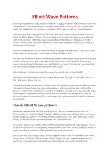
1. Register your machineBack to TOC1.1 Visit https://portal.nextwaveautomation.com to create a new UserAccount or open your existing account.UsernamePassword1.2 Click on the Hardware tab1.3 If your machine is already showing in this list, you can SKIP to Step 2.1on page 13.OR1.4 If your machine is not showing in this window click on the green buttonto add your machine.NOTE:For security reasons, your web browser may cause this screen to becomeunresponsive after a few minutes of idleness. If that happens, log back intoyour account to regain access to the screen.February 20207
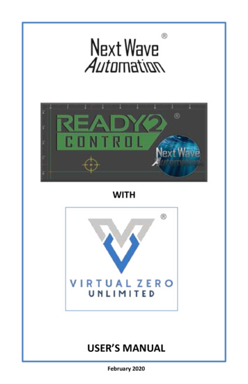
1. Register your machineBack to TOC1.5 Select your tool from thedrop down list.1.6 This window will pop-up.Continue to step 1.7 on thenext page.8Ready2Control User’s Manual
1. Register your machineBack to TOCTurn OFFTurn OFFPendant cable1.7 Turn off the power to the CNCShark or CNCPiranha control box andconnect Pendant Cable.- If your Pendant is already connected – you can skip to the next step.Always turn off the power to the control box before connecting ordisconnecting the Pendant or motor cables. Failure to do so can damagethe tool or parts.Turn ONTurn ONTurn ON1.8 Turn on the power to the control box.February 20209
1. Register your machineBack to TOC‘Enter Access Code” screen1.9 If the screen on your Pendant looks like the picture above, then recordthe serial numbers below and skip to step 1.11 on page 11.LCD Pendant #Controller #- If your pendant does not show the ‘Enter Access Code” Screen, skip tostep1.10a below.Pendant Main Control screen1.10a If the screen on your Pendant shows the Main Control screen thenPress the Apps button.10Ready2Control User’s Manual
1. Register your machineBack to TOC1.10b Press AboutLCD to open the LCDinfo screen.1.10c Then Open theAbout Controllerinfo screen. Recordthe serial numbersbelow.Apps screenRecord your LCDPendant Serialnumber:#About LCD screenRecord yourController Serialnumber:#About Controller screenFebruary 202011
1. Register your machineBack to TOC1.11 Using the information you gathered onpages 10 or 11, enter the Serial numbers foryour tool in Register Hardware window. Thenclick Register Hardware.1.12 Your machine should nowshow in the list. The Unlock AccessCode is also shown.Unlock Access Code1.13 Enter the Access Code in thependant and press Submit toUnlock the pendant. Then go tostep 1.14 below.If your pendant doesn’t show thisscreen, skip to step 1.14 below.‘Enter Access Code” screen1.14 The Access Code unlocksthe Pendant and makes the MainControl screen available (right).Machine registration is nowcomplete.This completes the MachineRegistration setup. Continue toSections 2 – Software InstallationMain Control screen12Ready2Control User’s Manual
START HERE – Section 2 – First time Software InstallationBack to TOC2.1 If need be, sign back into your portal account athttps://portal.nextwaveautomation.com2.2 Click on the Software tab and then the green button to add yoursoftware.Ready2Control2.3 Select Ready2Control from the dropdown list. Enter the AB License Paircodes that you received by email, or from the License Pair Card that camewith your tool. Then click Register Software.February 202013
2. First Time Software InstallationBack to TOCOpen/Save pop-up window2.4 Ready2Control now shows in the list. The download pop-up will alsoappear. Click Save File (See note below)NOTE: What happens after you press the Save File button will varydepending on the browser you are using. Some will automatically save thefile to your Downloads folder. Some may give you the option of picking afolder. The “Open/Save” pop-up window may look different and it may alsoautomatically disappear when you click the Save button.If the “Open/Save” pop-up window does disappear, check your Downloadsfolder – the file may be there.IF YOU NEED TO DOWNLOAD THE SOFTWARE AGAIN, click on thesoftware’s name in the list. A popup window will appear with a downloadlink.14Ready2Control User’s Manual
2. First Time Software installationBack to TOC2.5 Locate the file onyour computer anddouble click to open theinstall window.NOTE: You may need togrant permission toyour computer if it doesnot recognize theReady2Controlprogram.2.6 Check the I agreecheckbox and click theInstall button2.7 Click Launch to openReady2ControlFebruary 202015
2. First Time Software installationBack to TOC2.8 The Ready2Control logo screenwill appear briefly while theregistration window loads.2.9 Sign in to Ready2Register using the same Username and Password thatyou used for the Portal sign-in for Step 1.1 on page 7TIP: Check the box for Keep me signed in. This willhelp you streamline future updates and downloads.2.10 Click on USE SEAT to as assign a license to your computer.16Ready2Control User’s Manual
2. First Time Software installation2.11 Click CONFIRMBack to TOC2.12 Click CLOSE2.13 Check your email for your Software Key2.14 Copy and paste the Software Key into the Ready2Register window.Then click UnlockFebruary 202017
2. First Time Software installationBack to TOC2.15 Click Confirm2.16 Click Run2.17 The main Ready2Control control window opens. Nothing is active inthe window because you are not yet connected to your machine. This willtake place in the next step. Keep the Ready2Control program open.This completes the Software Installation section.Continue to Section 3 – Connecting your CNC machine.18Ready2Control User’s Manual
START HERE – Section 3 –Connecting your CNC machineBack to TOC3.1 Connect your CNC to your computer withan AB USB (Printer) cable.(It’s OK of the power is turned on for this step.CNC Shark Controller box USB cable hookupCNC Piranha Controller box USB cable hookupThis completes the Connecting your Machine section.Continue to Section 4 – Firmware UpdatesFebruary 202019
START HERE – Section 4 – Firmware updatesBack to TOCYour computer must be connected to the internet todownload the firmware updates.Your computer must be connected to your CNC machineduring the firmware update process.4.1 The first time you connect your CNC to Ready2Control, you will get aFirmware Out of Date notice. This section will step you through theprocess of updating the firmware for both the Pendant and the Control Box.The picture above shows Ready2Control using alight screen theme. Switching to a light screentheme is covered on pages 48 and 49, but youdon’t need to switch at this time.4.2 Click on the Ready2Update Firmware button. The Ready2Controlwindow will close shortly after the Install window below opens.20Ready2Control User’s Manual
4. Firmware updatesBack to TOC4.3 Check the I agree checkbox and the Install button.This will install a firmware updating program for the CNCShark andCNCPiranha.4.4 Click LaunchFebruary 202021
4. Firmware updatesBack to TOC4.5 The Ready2Update Firmware logo will briefly appear while the programloads.4.6 The What’s New window may appear. Click Close to continue.22Ready2Control User’s Manual
4. Firmware updatesBack to TOC4.7 Click the New – Download Controller button to start the install process.If you don’t see your machine listed or the Download buttons, click on theCan’t find machine link for help.4.8 The Firmware Installer window appears. The online instruction may behidden behind this window.February 202023
4. Firmware updatesBack to TOCInstructions windowInstall window4.9 Arrange the Instructions and the Install windows so you can see both.4.10 Complete (Steps 1 and 2) in the instructions. (Your controller shouldalready be connected to your computer with a USB cable)24Ready2Control User’s Manual
4. Firmware updatesBack to TOC4.11 (Step 3) Short the touchplate port. You can short the touchplate portin one of the two ways shown below and on the next page. This applies toboth the CNCShark controller (shown below) and the CNCPiranhacontroller.USB cableconnected toyour computerTouchplatecableShorting the touchplate port - Option 1 – The touchplate portcan be shorted by holding the touchplate magnet against the touchplate. This must be maintained for steps 4-7. Taping a steel washerto the aluminum plate makes this a little easier.February 202025
4. Firmware updatesBack to TOCTouchplate port1/8” drill bitShorting the touchplate port - Option 2 – Insert the smoothshank end of a 1/8-in. dia. drill bit into the touchplate port.4.12 (Step 4) Power on the controller.26Ready2Control User’s Manual
4. Firmware updatesBack to TOC(Step 5)(Step 6) – click button4.13 (Step 5) The Next Wave Firmware Installer window should now showDevice attached.4.14 (Step 6) Click Next Wave Controller Firmware buttonFebruary 202027
4. Firmware updatesBack to TOC4.15 (Step 7) The firmware update process is complete when theErase/Program/Verify Completed Successfully message appears.Close the Install window by clicking on the X in the upper right corner28Ready2Control User’s Manual
4. Firmware updatesBack to TOC4.16 (Step 8) - Power cycle the controller by following the steps below.- Turn OFF the controller- Remove the magnet from the touchplate or remove the drill bitfrom the touchplate port.- Turn ON the controller- Click OK to close the instruction window4.17 The Download Controller button should now be blue, signifying thatyour controller is up to date.February 202029
4. Firmware updatesBack to TOC4.18 Insert a USB flash drive into your computer.4.19 Click the New – Download Pendant button to start the install process.If you don’t see your machine listed or the Download buttons, click on theCan’t find machine link for help.30Ready2Control User’s Manual
4. Firmware updatesBack to TOC4.20 The download window opens. The USB flash drive (D:\ in this case) willautomatically be selected. Click DOWNLOAD to save update to the flashdrive. The instruction window (shown below) will appear when thedownload is complete.4.21 Complete Steps 1, 2 , 3 in the instruction window- Step 4 After few minutes a calibration screen will appear on thependant. Follow the calibration instructions on the pendant.- Step 5 A welcome screen (Next Wave logo) screen will display at the endof the calibration setup.4.22 Click OK to close the firmware Instruction windowFebruary 202031
4. Firmware updatesBack to TOCRemove4.23 Remove the USB flash drive from the pendantRemove files fromUSB drive*4.24 Insert the USB drive back into your computer and remove the 3pendant firmware files from the flash drive.*The files can be deleted or moved to a folder.The files should be removed because they can trigger the pendant to updateagain if you use the USB drive to run toolpath files on the pendant.32Ready2Control User’s Manual
4. Firmware updatesBack to TOC4.25 The Ready2Update – Firmware window may now look like this. ThePendant button may have disappeared because the Pendant was updated.Click the Refresh button to return the button.4.26 Both buttons should now appear blue signifying that the firmware isupdate-to-date. Click the X in the upper right corner to close this window.This completes the Firmware update section.Continue to Section 5 – Software UpdatesFebruary 202033
START HERE – Section 5 – Software updateBack to TOCYour computer must be connected to the internet to run thesoftware update.Your CNC does not need to be connected to your computer during thisupdate process – but it’s OK if it is connected.5.1 Open the Ready2Control program.5.2 If the Software Update flag is showing then anew version of the software is available.5.3 Click on the flag to start the update process.34Ready2Control User’s Manual
5. Software updateBack to TOC5.4 Click the UPDATE button5.5 Click the UPDATE button. This will start the update process.NOTE: The Ready2Control program will automatically close during theupdate process. The software cannot be updated while it is open.5.6 Check the I Agree boxand click the InstallbuttonFebruary 202035
5. Software updateBack to TOC5.7 Click Launch5.8 Connect your computerto the Controller and turn onthe controller.Your connected tool shouldbe showing in the lower rightcorner.This completes the START HERE - Software update section.You are now ready to use Ready2Control with your CNCShark or CNCPiranha.See page 37 for information on the main features and tools in R2Control.See page 57 for a Ready2Control Workflow GuideSee page 62 for a Virtual Zero Unlimited Workflow Guide36Ready2Control User’s Manual
Ready2Control overviewBack to TOC2.6.1.3.4.5.Main Control Panel windowThe R2Control main window contains six main sections:1. Menu Bar (see page 38)2. Update icons (see page 39)3. Job List, Virtual Zero and Run functions (see page 40)4. Viewport window and commands (see page 42)5. Machine controls (see page 43)6. General Settings (see page 48)More Settings menu (see page 55) Controller settings Software Shortcuts Registration window About window.For a step-by-step guide to the workflow ofReady2Control or Virtual Zero Unlimited see:Ready2Control Workflow Guide - page 58Virtual Zero Unlimited Workflow Guide - page 62February 202037
Menu BarBack to TOCFile menuLoad File – Loads a .tap cuttingfile to Job List window.Settings - Opens GeneralSettings window. See Page 48for more information.Exit - Closes Ready2Controlprogram. Ctrl Q – keyboardshortcut to Exit program.Help menuAbout– Opens the About window that contains Current Versioninformation and Change Log historyShortcuts - Opens the Ready2Control keyboard shortcuts window.View manuals – Access to the user manuals for Ready2Control and thecurrently connected machine. The most recent version of the manualdisplays when the software is connected to the internet.38Ready2Control User’s Manual
Update IconsBack to TOCFirmware Update IconWhen this icon is glowing yellow it means a machine firmware update isavailable. Clicking on the icon launches the Ready2Update – Firmwareapplication. It also automatically closes Ready2Control. See page 20 forinstruction on how to use Ready2Update to update the firmware for yourmachine’s control box and pendant.Software Update IconWhen this icon is glowing yellow it means aReady2Control software update is available. Clicking onthe icon launches Ready2Update for the software. It alsoautomatically closes Ready2Control. When Ready2Updatelaunches, follow the screen prompts to update thesoftware. Step-by-step information on updating thesoftware can be found on page 34.February 202039
Job List panelBack to TOCPress to toggle Virtual ZeroUnlimited on and off for thecurrently loaded .tap file.See page 62 for the Virtual ZeroUnlimited Workflow Guide.Press Load File to load a .tap cuttingfile. See page 58 for theReady2Control Workflow Guide.Shows that Virtual Zero Unlimited isactive for the current .tap file.The currently “loaded” file appearshere.Press Air Cut to test cut the loaded.tap file.Set Offset to thickness of thematerial plus a clearance amount.For example for .75” materialthickness add .25” clearance for anOffset amount of 1.00”. This willkeep the router bit at least .25”inches above your material duringthe Air Cut - when the Z is zeroed tothe top of the material.If the Z is zeroed to the bottom ofthe material, then the router bit willclear the material by at least 1”.Press this button toRUN/PAUSE/RESUMEthe cutting file.Press the E-STOP to stop the machine movement and cancel the cutting file.After pressing E-STOP the cutting file must be restarted from the beginning.For a temporary stop, use the blue Pause button40Ready2Control User’s Manual
(cont.) Job List panelBack to TOCHolding the cursor over the .tapfile name reveals the Pencil iconand the Trash icon.Use the Trash icon to delete the.tap file from the list.Click on the Edit icon to view theG-code for this file and to accessthe feed speed override slider(see below).G-code file. G-code can beviewed, but not edited.G-code editing will be available ina future “Pro” version ofReady2Control.Feed speed override sliderFebruary 202041
Viewport windowHorizontal andvertical linesrepresent the X Yzero locationsCenters the entirejob in the middle ofthe viewport.Back to TOCThe crosshairsshows the currentlocation of the tool(router bit center)relative to the XYzero location.Click to Move – Whenenabled, clicking on theViewport will move the tool(router/spindle) to that XYlocation on your machine.Toggles rulervisibility on and offClick this button tocenter the table area inthe viewport. You mustfirst Home the machinefor this options to work.42Visualize Height - Whenenabled toolpath lines thatare deep appear dark, shallowcuts appear light.Ready2Control User’s Manual
Machine control panelBack to TOCKeypad ENABLED viewThe Keypad ENABLED view provides quick access to axis keypad. You canactivate keypad by clicking on one of the axis position fields. This will openthe keypad control for that axis as shown at the bottom of this page.See page 50 on how to enable and disable the KeypadAxis Position fields- Show the current location ofeach axis.- Clicking on one of these fields willopen the Keypad control for thataxis – see bottom of this page.Arrow buttons – press arrows tomove axis in that direction.To change arrow buttons can also bechanged to the “classic” pendantstyle layout - see page 51.See pages 44 and 45for information onthese buttons andfunctionsAxis Keypad (pop-up view)Position fields- They show the currentlocation of each axis.- Clicking on a position field willactivate the keypad for thataxis and the keys will changecolor to match.- The location fields can beedited and used in conjunctionwith the Move to Position andSet Position buttons.- The keypad also functions as asimple calculator.February 202043
(cont.) Machine control panelBack to TOCKeypad DISABLED viewThe Keypad DISABLED view prevents access to the keypad. Instead axislocation can be entered directly in the axis position fields.See page 50 on how to enable and disable the Keypad.Axis Position fields- Show the current location ofeach axis.- When the Keypad is disabled,values can be entered directlyinto these fields and used inconjunction with the Move toPosition and Set Positionbuttons below.Jog speed setting (to changedefault speeds see page 49)Step – check this box to jog by theentered amount. (To set thedefault Step amount see page 49)Zero X, Y, Z, All Axes buttonsClicking these button will set thePosition field(s) to zero.See page 45 for information onthese buttons and functions44Ready2Control User’s Manual
(cont.) Machine control panelBack to TOC(Cont.) Keypad DISABLED viewRefresh Location button Click this button if Position fields failto update or if the machine stalls. Theneed to refresh can sometimes becaused by a underpowered computer,too many programs open or aprogram problem in Ready2Control. Ifyou frequently need to use theRefresh Location button, contactsupport@nextwaveautomation.comor call Ron at (419) 491-4520Move to Zero – Click this button tomove one or all axis to its zerolocation.Move to Position – Press this buttonafter entering an amount in one or allthe Axis Position fieldsSet Position – Press this button afterentering an amount in one or all theAxis Positions fields.ControllertoggleJobProgressConnectedtool nameZero with Touchplate – Press this button to start Z zeroing routine using aTouchplate. See page 46 for a step-by-step guide to using a touchplate.Home Machine – Press this button to start XY Homing routine(Only available on Piranha XL and CNC Shark tools that use a Pendant.)Safe Z – Enter the amount that you want the bit to raise above Z zerobetween cuts. Set to a height that keeps the bit from colliding with clamps orother objects. This amount can also be set in the Control settings window,see page 56.Job Progress – Shows the runtime and progress of the active job. Thecurrently connected tool name appears above the Job ProgressController Toggle – Switch control between Ready2Control and the Pendant.February 202045
(cont.) Machine control panelBack to TOCHow to Zero Z with a TouchplateThe Zero Z Touchplate is anaccessory available from yourlocal Next Wave Automationretailer or online atwww.nextwaveautomaiton.comStep 1Start the routine by clicking on theZero Z With Touchplate button.Step 2 Prepare the touchplate per the instruction in the pop-up windowThe Touchplate Thickness can be edited in this pop-up or in the ControlSettings window (see page 56). Editing the Touchplate Thickness is useful ifthe plate is slightly over or undersize or if you want the routine to set the ZZero slightly deeper or shallower. The Touchplate Thickness setting can alsobe used to accommodate the thickness of a custom-made plate.46Ready2Control User’s Manual
(cont.) Machine control panelBack to TOC(Cont.) How to Zero Z with a TouchplateStep 3 After the Confirmation notice appears, click NEXT.Step 4 The Z axis will move down until the tip of the router bit touches thetouchplate. It will then retract up to the Safe Z Height that was set in thecontrol panel (page 45).Step 5 Remove the magnet and touchplate from the machine beforeproceeding.February 202047
General SettingsBack to TOCSettings iconClick the Setting Icon to open the General Settings window (below)Additional setting and options can be access by clicking on the MoreSettings and More Option icons.General Settings windowSee the pages listed belowfor detailed information.More optionsOpens access to the HardReset option, which resetsall program functions tooriginal default settings.More settings menuOpens a menu with accessto additional settings andinformation windows.See page 55 for details.See page 49See page 50See page 52See page 49See page 53See page 5448Ready2Control User’s Manual
(cont.) General SettingsBack to TOCTheme SettingsThe Light themesetting uses a lightbackground colorThe Dark themesetting uses a darkbackground colorThe System Defaulttheme setting usesyour computer’stheme setting (light ordark or other)Speeds settingsUse this area to adjust the default jogging speeds for the three jog speedbuttons in the main control window.Default Speed – Sets the default jogspeed option in main Controlwindow. (See page 43)Slow, Medium, Fast - Set thedefault speed for each of thesesettings.Step Distance - Sets the default stepdistance when using the “Step”option in the main Control window.(See page 44 )February 202049
(cont.) General SettingsBack to TOCControl settingsCheck this box to enable theKeypad. When enabled theKeypad will pop-up when you clickin one of the axis position fields inthe main Control Panel (seebottom image)When checked the Keypad willreplace the direction controls.When unchecked the Keypad willappear as a separate pop-up whenclicking on one of the axis positionfields. (See images below)Axis position fieldsKeyboard “inline”Keyboard(enabled)pop-up50Ready2Control User’s Manual
(cont.) General SettingsBack to TOCControl settings (cont.)Checking the box makes theZero Axis confirmationmessage pop-up by default inthe main control window.Checking the box makes theMove to Zero confirmationmessage pop-up by default inthe main control window.IMPORTANT NOTE: Whenthis box is UNCHECKED, themachine will move to XYZzero when Move to Zerobutton is clicked in thecontrol panel.Click on the name dropdownmenu to toggle between theArrow Movement layout andthe Classic CNC Controlsbuttons. The Classic layout issimilar to the Pendant controlbutton layout.February 202051
(cont.) General SettingsBack to TOCViewport settingsDisplay Rulers – Check this box to make ruler visibilitythe default setting in the main Viewport window(See page 42)Visualize G-Code Height – Check this box to turn onthis option as the default in the main Viewportwindow. (See page 42)Z-Label Behavior(dropdown menu) The Z label becomes visible for a fewseconds each time the machine movesto a new X or Y or Z location. The Z label is always visible The Z label is always hidden( Z-Label as seen in themain Viewport window)52Ready2Control User’s Manual
(cont.) General SettingsBack to TOCVirtual Zero Unlimited (VZU)Recommended Points- These are “recommended” points that appear between the previouslycaptured points. When this box is checked, Recommended Pointsappear between the previously captured points that have a Z heightvariance greater than the Recommended Points Tolerance (see below)amount.- The Recommended Points function can be used as many times asnecessary until all captured points are within the Recommended PointsTolerance amount.- Check the box to make Recommended Points the default action in theVirtual Zero Unlimited application window (see page 73 for
Ready2Control includes a broad set of machine control tools useful in operating your Next Wave CNC tool from your computer. The powerful Virtual Zero Unlimited surface mapping application enables you to apply your CNC designs to a wide variety of curved and uneven surfaces. Pease read