Transcription
Section IIICROSS-SECTIONALANATOMYCHAPTER 15 Neuro AnatomyINTRODUCTIONCHAPTER 16 Thoracic AnatomyA radiologic technologist practicing in any field of radiologymust understand basic human anatomy and physiology inorder to perform his or her duties. Those working in CT orMRI must also be able to identify normal anatomic structures on cross-sectional images. This requires an adaptationin thinking; special attention must be paid to the relationships among structures. There are many excellent resourcesavailable that provide comprehensive images from theentire head and body, allowing readers to learn, identify,and recall anatomic structures in cross section. Some ofthese resources are listed here.CHAPTER 17 Abdominopelvic AnatomyCHAPTER 18 Musculoskeletal AnatomyThe aim of this section is to provide an introduction to cross-sectional anatomy by presentingjust a few representative slices from some of themost common examinations performed in theCT department. Each cross-sectional image isaccompanied by a drawing, in shades of gray, tohelp identify structures. All the drawings havebeen done according to the same gray scale. Regardless of where they are found in the body, airis depicted as black; bone is white. Within theseextremes, shading varies for tissues, organs, andabnormalities. Each cross-sectional image is alsoaccompanied by a reference image to help thereader imagine its location in the body.181Chap15.indd 18110/9/2009 2:36:20 PM
182Computed Tomography for Technologists: A Comprehensive TextBecause only representative slices are included,the slices displayed are not adjacent. Comparedwith an actual CT examination that includescontiguous slices, the reader is at a considerabledisadvantage in accurately identifying specificstructures from a single image. (Note: questionscontained in the certification examinationfor CT asking the examinee to identify anatomic structures most often provide only asingle cross-sectional image. Therefore, thisformat, although not reflecting actual practice,Chap15.indd 182does mirror that commonly used for the CTexamination.) In actual practice, wheneverthere is doubt the viewer should analyze adjacent superior and inferior images and comparethe structures in question.Resources:Madden ME. Introduction to Sectional Anatomy. Philadelphia: Lippincott Williams & Wilkins, 2001.Kelley LL, Peterson C. Sectional Imaging for ImagingProfessionals. St. Louis: Mosby/Elsevier, 2006.Dean D, Herbener TE. Cross-Sectional Human Anatomy.Philadelphia: Lippincott Williams & Wilkins, 2000.10/9/2009 2:36:24 PM
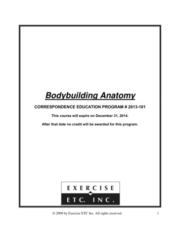
Chapter 15Neurologic Imaging Procedures183NEURO ANATOMYHEADABrainRoutine scans of the brain usually begin at the base of theskull and continue superiorly. Depending on the clinicalindication, the scans may be done without IV contrastenhancement, with IV contrast enhancement, or withoutand with IV contrast enhancement. The images includedbelow include IV contrast enhancement.B12121131045698Chap15.indd 18371.2.3.4.5.6.Nasal bonesEye, lensMaxillary sinusVomerSphenoid boneMedulla oblongata7. Occipital bone8. Vertebral artery9. Mastoid air cells10. Zygoma11. Eye, globe12. Ethmoid sinus10/9/2009 2:36:26 PM
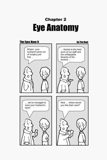
184Computed Tomography for Technologists: A Comprehensive TextA114223134512681199710B1.2.3.4.5.6.Chap15.indd 1841. Medial rectus m.2. Globe of eye3.MedialOptic n.rectus m.4.GlobeSphenoidbone,of eyegreater wing ofOptic n.5. Mandibular condyleSphenoid bone,6. Mastoid air cellsgreater wing ofin left temporal boneMandibular condyle7. Sigmoid sinusMastoid air cellsin left temporal bone8. Pons9. Cerebellum10.auditory7.InternalSigmoidsinus canal11.8.AuriclePons12.auditory meatus9.ExternalCerebellum13.rectusm. 12. External auditory meatus13. Lateral rectus m.14. Zygoma10/9/2009 2:36:30 PM
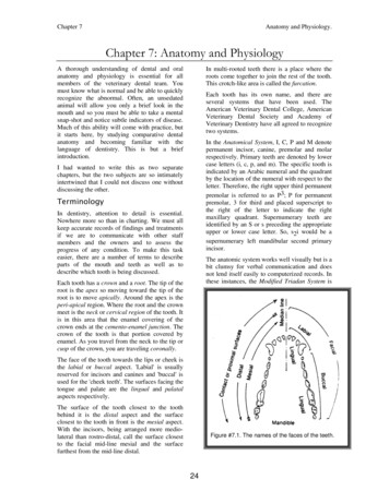
Neurologic Imaging lsinussinus1. Frontal2.Pituitary2. Pituitary3.Sphenoidbonebone3. Sphenoid4.Middlecerebral4. Middle cerebral a.a.5.Temporallobelobe5. Temporal6.Mastoidaircells6. Mastoid air sinussinus7. Sigmoid8.Occipitalbonebone8. OccipitalChap15.indd 185B9. Cerebellarpeduncles9. Cerebellarpeduncles10.Cerebellum10. re12.Fourthventricle12. Fourth ventricleBasilar13.13.Basilara. a.14.Sellatursica14. Sella tursica15.Temporalis15. Temporalis m. m.Frontalbone,orbital16.16.Frontalbone,orbitalroof roof10/9/2009 2:36:31 PM
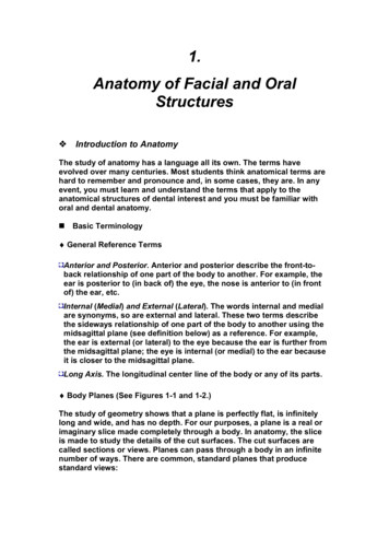
186Computed Tomography for Technologists: A Comprehensive TextA121231141059678B1.2.3.4.5.Frontal bonecerebri1.FalxFrontalbonecerebral a.2.AnteriorFalx cerebricerebrala. ,cerebral a.5.temporalLateral ventricle,horntemporal horn6. Parietal bone6. Parietal boneChap15.indd 1867. Cerebellum, tentoriumInternal occipital7.8.Cerebellum,tentoriumprotuberance8. Internaloccipital9.protuberanceFourth ventricle9.Fourthventricle10.Posteriorcerebral a.10.Posteriorcerebral a.11. Basilar a.11.a. bone12.BasilarTemporal12. Temporal bone10/9/2009 2:36:33 PM
Neurologic Imaging Procedures187A1122141335445612 12117108B91. Superior sagittal sinusFrontalsagittalbone sinus1.2.Superior3.Lateralventricle,2. Frontal boneanteriorhorn3. Lateralventricle,4.Caudateanteriorhornnucleus, headPutamen/Globuspallidus4.5.Caudatenucleus, headThird ventricle ntricle8. Parietal . Internal occipital10.protuberenceCerebellar vermis11.Pineal body10. Cerebellarvermis12.Thalamus11. Pinealbody13.Internal capsule12. Thalamus14.Temporalbone13. Internalcapsule7. Choroid plexus14. Temporal boneChap15.indd 18710/9/2009 2:36:34 PM
188Computed Tomography for Technologists: A Comprehensive TextA121110394387B751261. Falx cerebri7. Occipital lobe1. Falx cerebri6. Superior sagittal sinus2. Frontal bone8. Choroid plexus2. Frontal bone7. Occipital lobe3. Corpous callosum9. Lateral ventricle, body3. Corpous callosum8. Choroid plexus4. Caudate nucleus, body10. Temporal bone4. Caudate nucleus, body9. Lateral ventricle, body5. Parietal bone11. Corona radiata5. Parietal bone10. Temporal bone6. Confluence of sinuses (torcula)12. Straight sinus11. Corona radiata12. Straight sinusChap15.indd 18810/9/2009 2:36:36 PM
Neurologic Imaging Procedures189A102983114671. Frontal lobeFrontal lobe2. 1.Superiorsagittal sinus2.Superior sagittal3. Precentralgyrus sinus3.Precentralgyrus4. Central suicus4.Centralsuicus5. Falx cerebri5. Falx cerebri6. Parietal lobeChap15.indd 18965B6. Parietal ne10/9/2009 2:36:37 PM
190Computed Tomography for Technologists: A Comprehensive TextSinusesSinus screening is intended as an inexpensive, accurate,and low radiation dose method for confirming the presence of inflammatory sinonasal disease. If confirmed andthe patient will then have endoscopic sinus surgery, thecoronal images provide a “roadmap” for the surgeon.When the clinical indication is recurrent or chronic sinusitis, the study is done without IV contrast enhancementand scanning is done in the coronal plane. Other clinicalindications may require the administration of IV contrastor additional scans in the axial plane.Sinuses p15.indd 190Sphenoid bone1.SphenoidboneSphenoid a tursica, floor4.MedialZygomapterygoid m.5.MasseterMedial pterygoidm.m.6. Masseter m.7. Mandible7. PharynxPharynx10.bone10. HyoidHyoidbone11.m.m.11. LateralLateralpterygoidpterygoid12.12. 9 2:36:39 PM
Neurologic Imaging 9B1.2.3.4.5.6.7.8.9.10.Chap15.indd 191Frontal lobe1. Frontal lobeMedial rectus m.2. Medial rectus m.Superior rectus m.3. Superior rectus m.Infraorbital fissure4. Infraorbital fissureNasal conchae5. Nasal conchaeMaxillary sinus6. Maxillary sinusZygoma7. ZygomaMaxillary bone8. Maxillary boneHard palate9. Hard palateMandible11. Tooth10. Mandible12. Nasal bone (nasal septum)11. Tooth13. Inferior rectus m.12. Nasal bone (nasal septum)14. Lateral rectus m.13. Inferior rectus m.15. Optic nerve/ canal14. Lateral rectus16. Sphenoid sinus15. Optic nerve/ canal17. Tongue16. Sphenoid sinus18. Oral vestibule17. Tongue19. Masseter m.18. Oral vestibule19. Masseter m.10/9/2009 2:36:42 PM
192Computed Tomography for Technologists: A Comprehensive hap15.indd 192Cristagalli galli9.1. CristaEthmoidsinus sinus10.2. EthmoidMedialrectusrectusm.3. Medialm.Frontalbone bone11.4. FrontalInferiorrectusrectusm.12.5. Inferiorm.Middlenasal turbinate6. Middlenasal turbinate 13.Maxillarysinus sinus14.7. MaxillaryInferiornasal turbinate8. Inferiornasal turbinate r obliquem.m.14.Superiorobliquem.Eye, globe15. Eye, globe10/9/2009 2:36:44 PM
Neurologic Imaging 6.7.Chap15.indd 193Frontal lobe1. Frontal lobeEye, globe2. Eye, globeLacrimal gland3. Lacrimal glandInferior rectus m.4. Inferior rectus m.Maxillary sinus5. Maxillary sinusMaxillary bone6. Maxillary boneTooth7. Tooth8. Tongue10B8. Tongue9. Oral vestibule9. Oral vestibule10. Mandible10. Mandible11. Inferior nasal chonchae11. Inferior nasal chonchae12. Nasal bone (nasal septum)12. Nasal bone (nasal septum)13. Middle nasal chonchae13. Middle nasal chonchae14. Ethmoid sinus14. Ethmoid sinus10/9/2009 2:36:45 PM
194Computed Tomography for Technologists: A Comprehensive TextTemporal BonesThe organs of hearing and balance are located in the petrous ridge of the temporal bone. Because these organs aretiny, thin slices are used. Once the scan data are acquired,the two petrosal bones are reconstructed separately sothat the display field of view can be reduced to ensureoptimal resolution. Most protocols include scans in boththe coronal and axial planes; the use of IV contrast variesaccording to the clinical indication.Temporal Bones leusFacial canalCochleaInternal auditory canalTympanic cavityMastoid air cellsTemporal boneSemicircular canalsHypoglossalc analOccipitalc ondyleJugularf dd 19410/9/2009 2:36:48 PM
Neurologic Imaging Procedures1951. Internal auditory canal1. Internal auditory canal2. Superior semicircular canal2. Superior semicircular3. canalLateral semicircular canal4. 3.EpitympanumLateral semicircular canal5. 4.IncusEpitympanum6. 5.ExternalIncus auditory canal7. 6.StyloidprocessExternalauditory canal8. 7.TympaniccavityStyloid process9. 8.OvalwindowTympanic cavity9. Oval window435291687Chap15.indd 19510/9/2009 2:36:53 PM
196Computed Tomography for Technologists: A Comprehensive TextTemporal Bones (Axial)1.2.3.4.5.6.7.8.Mandible, condyleSphenoidsinus1. Mandible,condyleClivus2. Sphenoid sinusCarotidcanal3. ClivusSigmoidnus4. CarotidsicanalMastoidair cells5. SigmoidsinusExternalauditorycanal6. Mastoidair cellsJugularforamen7. Externalauditory canal9. Auditory ossicle: malleus10.Auditoryossicle: incus8. Jugularforamen11.Carotid ossicle:acnal malleus9. Auditory12.10.InternalAuditoryauditoryossicle: canalincus13.11.VestibuleCarotid canal14.canalcanal12.SemicircularInternal auditory15.Cochlea13.Vestibule14. Semicircular canal15. p15.indd 1961410/9/2009 2:36:55 PM
Neurologic Imaging Procedures15-181.2.3.4.5.6.7.197Temporal lobe1. Temporal lobeSuperior semicircular canal2. Superior semicircular canalMastoid antrum3. Mastoid antrumPosterior semicircular canal4. Posterior semicircular canalSigmoid sinus5. Sigmoid sinusTemporal bone6. Temporal boneOccipital bone7. Occipital bone15-171263457Chap15.indd 19710/9/2009 2:37:01 PM
198Computed Tomography for Technologists: A Comprehensive TextNECKUnless contraindicated, CT examinations of the neck aredone with the IV administration of contrast media. Artifacts caused by dental work often obscure surroundingstructures at some levels. Some facilities split the data acquisition into two groups so that the gantry can be angledto reduce artifact. However, many MDCT systems do notallow the gantry to be angled in the helical mode, so thisis not always 16.17.Maxillary boneOral vestibuleMasseter m.Mandible, ramusAtlas, anterior archDensSpinal cordInternal jugular v.Mastoid tipParotidg landRetromandibularv .Internal carotid a.PharynxGenioglossusm.Vertebrala .Vertebra, spinous processLongus colli muscles15-1815-1918. Rectus/oblique capitus m.19. Splenius capitus m.20. Pterygoid 310108187151816Chap15.indd 19810/9/2009 2:37:03 PM
Neurologic Imaging Procedures1. 1.GenioglossusGenioglossusm.m.2. 2.TongueTongue3. 3.MandibleMandible4. 4.PharynxPharynx5. 5.LeftLeftexternalexternalcarotidcarotid a.a.6. 6.InternalInternaljugularjugularvv.v.1997.9. VertebralLeft internala. carotid tvertebral a.glandSubmandibular10. Sternocleidomastoid m.11. Submandibular gland7. Left internal carotid a.8. Vertebral body1353112117410668109Chap15.indd 19910/9/2009 2:37:16 PM
200Computed Tomography for Technologists: A Comprehensive Text2121456134136758712119101. Sternohyoid/Sternothyroid mm.1. Sternohyoid/Sternothyroid mm.2. Thyroid cartilage2. Thyroid cartilage3. Cricoid cartilage3. Cricoid cartilage4. Sternocleidomastoid m.4. Sternocleidomastoid m.5. Jugular vv.5. Jugular v.6. Thyroid gland6. Thyroid gland7. EsophagusChap15.indd 2009108. Vertebral body7. Esophagus9. Erector spinae m.8. Vertebral body10. Trapezius m.9. Erector spinae m.11. Right vertebral a.10. Trapezius m.12. Right common carotid a.11. Vertebral a.13. Pharynx12. Common carotid a.13. Pharynx10/9/2009 2:37:23 PM
Neurologic Imaging Procedures201SPINECT of the spine is most often performed without IV contrast media administration. However, scans of the spineare often obtained after intrathecal contrast material isgiven for a myelography dd 201Aorta1. AortaPsoasm.2. PsoasDuralsac m.3. Dural sacPedicle4. PedicleLumbarvertebra 25. LumbarArticularfacetvertebra 26. Articular facet7. Ligamenta flava8.7.LigamentaL1, spinousflavaprocessL1, transversespinous process9.8.L2,processL2, transverseprocess10.9.Erectorspinae m.Erector spinae m.11.10.KidneysKidneys12.11.Jejunum/ileum12. Jejunum/ileum10/9/2009 2:37:26 PM
202Computed Tomography for Technologists: A Comprehensive d 202Inferior vena cava1.AortaInferior vena cava2.L2,Aortavertebral body3.PsoasL2, a6.L2,L2,spinouslamina process7. L2, spinous process8. Multifidus m.8. Multifidusm.9.Erector spinaem.9.Erectorspinae10. Cauda equina m.(in dural sac)10. RightCaudakidneyequina (in dural sac)11.11.Rightkidney12. Nerve root (exiting)12. PosteriorNerve rootlongitudinal(exiting) lig.13.13. Posterior longitudinal lig.10/9/2009 2:37:33 PM
Neurologic Imaging d 20355106Inferior vena cava7.Aorta8.1. Inferiorvena cavaAnulusfibrosus9.2. AortaIntervertebraldisk L2/L310.3. isk L2/L312.L2,4.spinousprocess5. Articular processes6. L2, spinous process1257Erector spinae m.Psoas m.7. Erectorspinae m.Rightkidney8. Psoas m.Ligamentaflava9. RightDuralsackidney10. Ligamentaflava m.Quadratuslumbrum11. Dural sac12. Quadratus lumbrum m.10/9/2009 2:37:37 PM
186 Computed Tomography for Technologists: A Comprehensive Text A B 2 3 6 8 10 4 1 5 1. Frontal bone 2. Falx cerebri 3. Anterior cerebral a. 4. Middle cerebral a. 5. Lateral ventricle, temporal horn 6. Parietal bone 7. Cerebellum, tentorium 8. Internal occipital protuberance 9. Fourth