Transcription
The following article was published in ASHRAE Journal, April 2005. Copyright 2005 American Society of Heating, Refrigerating and AirConditioning Engineers, Inc. It is presented for educational purposes only. This article may not be copied and/or distributed electronically orin paper form without permission of ASHRAE.Data CentersStaying On-line:Data CenterCommissioningBy Mark Hydeman, P.E., Member ASHRAE; Reinhard Seidl, P.E., Member ASHRAE; and Charles Shalley, P.E.Data centers require tight coordination between the trades, specialconsideration for redundancyand reliability, and carefully scriptedcommissioning of systems. Consider,for example, the issue of redundancy.For non-critical commercial facilities,the design for redundancy typically isapproached on an equipment basis.For example, in a chilled water plantwith a 1,000 ton (3517 kW) load, three 500ton (1760 kW) chillers may be provided tomeet the requirement of N 1 redundancy.With this design, in theory, any chiller canbe pulled out of service and the plant cancontinue to serve the design load. Withan office building, this simplistic viewof redundancy may be sufficient. Failureto meet the design load merely causesan inconvenience to tenants; it does notcompromise the core business.With data centers and other missioncritical facilities, engineers are challenged60ASHRAE Journalto think in terms of system failures, andmore sophisticated techniques are requiredto analyze critical links. In our previousexample, consider the failure of an electrical panel that serves two or all three ofthe chillers. Although the chillers weredesigned for N 1 redundancy, a failure ofthe electrical feed to more than one chillercan shut down the data center.As compared to the office building,the risk of failure in data centers is compounded by several issues: 1) with highdensity loads, the time for recovery fromequipment or system failure is muchshorter; 2) the cost of failure is muchhigher; and, 3) as loads may cluster withinany group of racks, redundancy must beprovided in the “downstream” distribution system as well as the central plant.This article presents a process that can beused to review and test the system design toachieve a high degree of system reliability.It also emphasizes the importance of closeashrae.orgcoordination required in the design of theelectrical, mechanical and control systemsand summarizes the experience of twofirms (one mechanical and one electrical)that have collaborated in the design andcommissioning of many data centers.A Commissioning ProcessThis article cannot comprehensivelycover all of the steps in commissioning adata center, but it highlights the four keysteps and provides examples from realprojects for each. These steps are: Design review; Preparation for functional testing;About the AuthorsMark Hydeman, P.E., is a principal at Taylor Engineering in Alameda, Calif. He is a corresponding member of ASHRAE Technical Committee9.9, Mission Critical Facilities, Technology Spacesand Electronic Equipment.Reinhard Seidl, P.E.,is a senior engineer at Taylor Engineering.Charles Shalley, P.E., is a principal emeritus atthe Engineering Enterprise in Alameda, Calif.April 2005
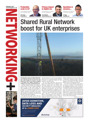
With data centers and other mission critical facilities, engineers are challenged to think in terms ofsystem failures . Implementation of the functional tests;and Review of trends and tests.Obviously, these steps are part ofan iterative process that must react toproblems uncovered in the field. In ourexperience, no script can cover all of thecontingences that include field installation, control sequences, equipment internal controls and configuration, unit delaysand unanticipated issues uncovered in thecommissioning process.Design ReviewWhether acting as a third-party commissioning agent or as the engineersof record, we have found a peer review(either internal or external) by someoneother than the actual designer to be animportant part of the design process.Having outside eyes take a fresh lookat the design often uncovers designcontingencies that the designer had notconsidered. In addition to the normalitems under a peer review, a review ofa data center must carefully considerfailure modes, operation at part load andcoordination of controls as discussed inthe following paragraphs.Failure Modes: Both the designer andreviewer need to consider what will happenon failure of any piece of equipment or support system. Data center support systemsare complex and interwoven: the mechanical, electrical and control systems must bereviewed as a whole since failure in any onemay cascade to failures in the others.For instance, loss of utility power ina data center will cause the emergencygenerator systems to come on-line. Themechanical design must consider not onlythe continuation of cooling throughoutthe process but also the power-off andrestart sequences of the mechanicalApril 2005equipment to prevent overloading thegenerator when it comes on-line.This is complicated by the internallockout of mechanical cooling equipment, which might prevent or delay restart of a chiller or direct expansion (DX)unit if it fails on loss of power. Often thesettings on these internal delays (or thenumber of restarts) have to be adjustedfor fail-safe operation.Many branches of engineering, including aerospace, materials science andindustrial, provide formal training inthe field of failure analysis. A brief Websearch on “failure analysis” or “reliabilityanalysis” results in a range of universityprograms, magazines, consulting firmsand software. Unfortunately in the HVACindustry, we have little formal training,guidance or tools geared for this work.Chapter 17, “Data Processing andElectronic Office Areas,” of the 2003ASHRAE Handbook—HVAC Applications simply states,“System reliability is so vital that thepotential cost of system failure mayjustify redundant systems, capacity,and/or components. The designershould identify potential points offailure that could cause the systemto interrupt critical data processingapplications and should provide redundant or back-up systems.”Although the statement is true, themeans for analyzing the modes of failureare not presented in the ASHRAE handbooks or guidelines.*A rigorous analysis of system reliability requires statistical modeling ofcomponents and systems combined witha method of stepping through the array*ASHRAE TC 9.9, Mission Critical Facilities, Technology Spaces and Electronic Equipment, is making a major revision to this Handbook chapter.of possible fault propagation modes suchas Monte Carlo tml)or Fault Tree Analysis (http://reliability.sandia.gov/Reliability/Fault Tree Analysis/fault tree analysis.html).Most mechanical and electrical designers do not perform these kinds of analyses,either because their fees in a competitivemarketplace do not allow it, or becausethey do not have the required experience tomake use of statistical tools. Another barrier is the lack of historical statistical dataon equipment failure, which is a requiredinput to some of these programs.A simple failure analysis can be done byhand or implemented in a spreadsheet. Theprocess needs to be thorough and methodical. Using the example central plant shownin Figure 1, we can see what happens if thecontrol panel CP-1 fails. CP-1 controls theprimary chilled water pump PCHP-1. Withfailure of this panel the pump also fails.Chiller CH-1, in turn, relies on PCHP-1and detects its failure as a loss of flow.Consequently, CH-1 shuts down.Chillers 1, 2 and 3 run lead/lag/standbywith each chiller having 50% of total capacity. As a result of CH-1 shutting down,the remaining chillers CH-2 and CH-3will run and can still provide 100% totalcapacity. The central plant, therefore, isable to provide the design capacity onfailure of control panel CP-1.A failure of CP-3, on the other hand,would shut down both of the condenser water pumps (CWP-1 and CWP-2). The lackof condenser water flow would prevent anyof the three chillers from running, leavingthe plant with 0% capacity. This clearly isa design flaw that needs to be fixed.A spreadsheet can be automated tosimulate failure of each piece of equipment in turn. As each piece of equipmentASHRAE Journal61
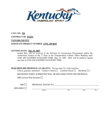
is failed in the automation, the software also should note the quence requires the generators to communicate to the mechanifailure of dependent equipment (e.g., a chiller that relies on the cal control system the loss of power and subsequent readiness ofoperation of a condenser water pump), then test if the remaining the generators to accept load. The mechanical and electrical bidequipment has sufficient capacity to supply 100% of the load. documents must be reviewed to ensure that all interconnectionsThe simulation should flag any piece of equipment that results and associated sequences are fully specified, communicationin less than 100% design capacity when failed. This discovery protocols are matched on each end, and that the scope of workshould lead to the redesign of the system (such as the condenser for each contractor is clearly outlined. Even within a trade, carewater pumps in the earlier example).must be taken to coordinate the passage of information betweenWhile using common sense to analyze failures is possible, equipment from various manufacturers.some weak links may be overlooked. This simplistic analysisAnother issue to consider is provision of uninterruptibleneither accounts for the timed lockout for chiller restart dis- power supply (UPS) power to the control system panels. Thiscussed previously, nor does it cover the event of coincident generally can be provided at a low incremental cost because thefailures of more than one piece of equipment.control panels are low wattage devices. Uninterrupted power toPart-Load Operation: With data centers, consideration of the control panels can greatly improve the stability of systemshow the equipment unloads is important. Although the computer during the power down restart sequences.equipment within the center tends to run close to full load, mostcenters are phased in with racks being installed in groups over Preparation for Functional Testingtime. Furthermore, many of the assumptions for the expectedFunctional Test Scripts: Functional test scripts like the exampleload density change shortly after the data center becomes op- shown in Figure 2 should be developed for each major piece oferational, or sometimes during conequipment, all control reset sequences,struction. Because of this, most dataall equipment staging, and all anCP-1 CP-2 CP-3CT-2CT-1centers are built either with futureticipated failure scenarios. Note thesecapacity already installed, or withscripts supplement and don’t replaceprovisions for future capacity to bethe system prefunctional tests (likeadded in later construction phases.hydronic pressure testing of the chilledCH-1PCHP-1During startup, systems usually arewater piping), contractor startup orrunning at part-load.control system commissioning (suchCH-2The design of the equipment andas the point-to-point verification andPCHP-2systems supporting the data centertesting of sequences).must take into account part-loadThe example in Figure 2 is a testCH-3operation during the initial startup,scriptfor secondary chilled waterSCHP-1PCHP-3and (as appropriate) uninterruptedpumps. These pumps are controlledoperation as subsequence phaseswith variable speed drives and areSCHP-2are built out. For initial startup ofdesigned to operate in parallel forthe data center and each subsequentbetter redundancy.CWP-1phase of build-out, the coolingLoad Banks: As previously disCWP-2systems must be evaluated for theircussed, the data center generally willability to stay on-line and the provi- Figure 1: Schematic of example control plant.not be fully loaded during systemsion of redundancy.startup and commissioning. In mostFor pumps, fans and compressors (chillers and DX units) the cases, the computer systems are installed into the racks duringreview should ensure proper unloading controls are specified, and the final phases of construction or just after commissioning, butthat the part-load operation is well away from the surge regions. To provide little or no heat load for system testing. Load banks typiprevent temperature fluctuations and premature equipment failure, cally are used to introduce heat loads and to allow simultaneouscompression cooling should operate at the lowest anticipated load testing of both electrical and cooling systems.levels without excessive cycling.Renting and operating load banks is costly, and introduceFor cooling towers, the reviewer should ensure that the tower risk—if cooling fails, load banks can quickly overheat a spacecells are designed for the highest and lowest anticipated flows and potentially trigger sprinkler systems. This means that thewith proper coverage of the fill. Variable speed fans or tower time for using load banks and associated operators must bebypass should be considered to keep the condenser water tem- minimized. For large projects, a sufficient number of load banksperature stable under low loads.must be reserved in advance to ensure availability.Controls: Successful control of data center systems requiresThe mechanical, electrical and control systems must all becareful coordination of the control design for the mechanical ready to run when load banks arrive and the functional testsand electrical equipment. A successful power down restart se- are to be run:62ASHRAE Journalashrae.orgApril 2005
A. Chilled Water System1. Secondary chilled water pumps and associated VFDs:a. Operation: Both pumps are designed to operate continuously. The control system shall modulate the speed of both pumps through the VFDs to controlthe differential pressure at the end of the piping system to a constant pressure setpoint.b. Failure tests:(1) Disconnect the differential pressure transmitter.(a) Confirm that both pumps continue to operate at a constant speed (speed shall be per the last signal given).(b) Confirm that the BAS is in alarm.(c) Confirm that the owner’s representative(s) have been paged.(d) Confirm proper operation after the sensor has been reconnected.(2) Disable the entire BAS (panels) in the building.(a) Confirm that both pumps continue to operate at a constant speed (speed shall be per the last signal given).(b) Confirm that the BAS is in alarm.(c) Confirm that the owner’s representative(s) have been paged.(d) Confirm proper operation re-enabling the BAS in the building.(3) Disable the BAS control panel serving the pump VFDs.(a) Confirm that both pumps continue to operate at a constant speed (speed shall be per the last signal given).(b) Confirm that the BAS is in alarm.(c) Confirm that the owner’s representative(s) have been paged.(d) Confirm proper operation after re-enabling the control panel.Figure 2: Functional test script for secondary chilled water pumps. The support systems, generators, UPS and power distributionsystems must be complete. Control systems must be programmed and ready to trendequipment operation. Chillers and associated hydronic systems, as well as computer room air conditioner (CRAC) units, package units,DX systems and any other installed equipment must havecompleted startup and be ready for operation. Chillers willnot stay on-line without significant load, so they can be runonly once load banks are started.Coordination of the Trades: Preparation for these tests is amultidisciplinary effort that requires input from both the designand construction teams. The functional tests cover not onlyindividual pieces of equipment but also the entire integratedmechanical, electrical and control systems. Designers andcontractors of these systems should provide input to the scriptwell in advance of the scheduled commissioning dates.We have found that holding regular commissioning meetings for several months before actual commissioning serves toraise awareness of critical issues in all of the team members.Engineers, owners, contractors and equipment vendors can usethese meetings to agree on sequence of events, coordinationof schedules and responsibilities of key players. Schedulingconsiderations should include these milestones: A date for power to all the mechanical and control systems; A final date for precommissioning of all systems, which includesthe typical startup for each piece of equipment and testing ofall control system wiring, I/O point status, programming, configuration of alarms and configuration of trending. The trendsand alarms must be active during the functional tests. Arrival of load banks and duration of testing. Expected timeto perform all testing, including:· Part-load and full-load (where possible) operation;· Sequenced failure of equipment, restart and return toApril 2005stable operation. This should be done for every piece ofequipment;· Automatic transfer switch (ATS) and UPS operation;· Generator operation; and· Complete power-down and automatic restart. Startup, prefunctional testing and functional testing of eachsystem. The mechanical and controls contractors need to carefully coordinate the testing of their systems with the electricalcontractors to ensure uninterrupted power is available duringtheir tests. All three trades are typically testing their systemssimultaneously. Contingency time reserved for correction of errors andretesting.Execution of Functional TestsDuring the development of the functional test scripts a commissioning log should be created from the script that can be usedto record the event. An example log is shown in Figure 3. Thislog should record the events that occur during testing in parallelwith automatic monitoring and trend logs from control systems.Recorded information should include: date and time of testing, theparticipants, and the expected and actual outcomes for each test.During testing, frequently unexpected results occur due tosystem attributes that were overlooked during design or introduced during construction. One such example is given in Figure3. Test 1.b.3 illustrates the test of dual secondary chilled waterpumps with variable speed drives. According to the controlsequences, failing the control panel of the variable speed drivesshould result in maximum speed from both drives and a controlsystem alarm to the operator.Note that in this case, redundancy was designed not by providing separate control panels to both drives, but by allowing drivesto run to maximum speed after loss of the control signal. As theactual test log shows, both drives initially went to zero speed andASHRAE Journal63
Project:Eng:Date:Test No.1.b.3Present:Pass/FailFailTimeJune 28 12:04FailFailFailFailDescriptionDisable the BAS control panel serving the pump VFDs.(a) Confirm that both pumps continue at constant speed.(b) Confirm that the BAS is in alarm.(c) Confirm owner’s representative(s) have been paged.(d) Confirm operation after BAS has been reconnected.VariablesResultspeed msg 0% none Note that with eight different speeds, using three binary inputs at the drive. Two solutions exist:(a) Never allow drives to be disabled during normal operation. Upon failure of panel, drive will no longer be enabled.Program drive to run to 60 Hz in this case. Drives should never be intentionally disabled during normal usage (there is nostaging sequence), so the only disable command will occur on service. For service, the mechanic will switch local disconnect to “off” position. No drive disable through BAS is therefore ever required.(b) Run a separate set of wires to each drive, using the second of three inputs on the drive, a failure condition can nowbe sensed in addition to an intentional disable command. The drive will then go to zero speed upon disable, 27 Hz on 0%speed input, and 60 Hz upon power failure at panel. This option is more elegant, but adds little effective functionality.June 29 14:20 After resetting of drive interface, retest. Drives now go into error condition. Need to reprogram.July 111:55 Drives remain in constant sp
commissioning of many data centers. A Commissioning Process This article cannot comprehensively cover all of the steps in commissioning a data center, but it highlights the four key steps and provides examples from real projects for ea