Transcription
Reactor Concepts ManualPressurized Water Reactor SystemsPressurizedWaterReactor(PWR)SystemsFor a nuclear power plant to perform the function of generating electricity, many different systems mustperform their functions. These functions may range from the monitoring of a plant parameter to thecontrolling of the main turbine or the reactor. This chapter will discuss the purposes of some of themajor systems and components associated with a pressurized water reactor.USNRC Technical Training Center4-10603
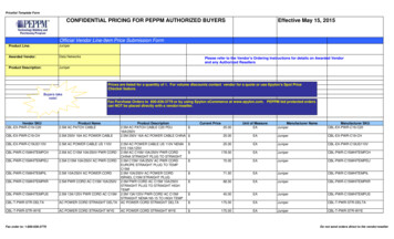
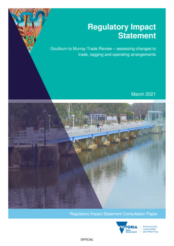
Reactor Concepts ManualPressurized Water Reactor SystemsCONTAINMENT BUILDINGREACTORCOOLANT SYSTEMMSRELECTRICGENERATORS/GPZRHPLPCOOLING TOWERMAINTURBINEMAINCONDENSERRHRHXRHRPUMPAUXILIARY BUILDINGCORERCPMAIN FEEDPUMPCONTAINMENTSUMPFWHTRCONDENSATEPUMPCIRC. WATERPUMPTURBINE BUILDINGThere are two major systems utilized to convert the heat generated in the fuel into electrical power forindustrial and residential use. The primary system transfers the heat from the fuel to the steam generator,where the secondary system begins. The steam formed in the steam generator is transferred by thesecondary system to the main turbine generator, where it is converted into electricity. After passingthrough the low pressure turbine, the steam is routed to the main condenser. Cool water, flowingthrough the tubes in the condenser, removes excess heat from the steam, which allows the steam tocondense. The water is then pumped back to the steam generator for reuse.In order for the primary and secondary systems to perform their functions, there are approximately onehundred support systems. In addition, for emergencies, there are dedicated systems to mitigate theconsequences of accidents.USNRC Technical Training Center4-20603
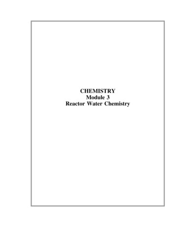
Reactor Concepts ManualPressurized Water Reactor NERATORThe primary system (also called the Reactor Coolant System) consists of the reactor vessel, the steamgenerators, the reactor coolant pumps, a pressurizer, and the connecting piping. A reactor coolant loopis a reactor coolant pump, a steam generator, and the piping that connects these components to thereactor vessel. The primary function of the reactor coolant system is to transfer the heat from the fuelto the steam generators. A second function is to contain any fission products that escape the fuel.The following drawings show the layout of the reactor coolant systems for three pressurized waterreactor vendors. All of the systems consist of the same major components, but they are arranged inslightly different ways. For example, Westinghouse has built plant with two, three, or four loops,depending upon the power output of the plant. The Combustion Engineering plants and the Babcock& Wilcox plants only have two steam generators, but they have four reactor coolant pumps.USNRC Technical Training Center4-30603
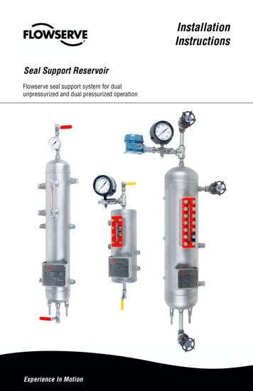
Reactor Concepts ManualPressurized Water Reactor REACTORA two-loop Westinghouse plant has two steam generators, two reactor coolant pumps, and a pressurizer.The two-loop units in the United States are Ginna, Kewaunee, Point Beach 1 and 2, and Prairie Island1 and 2. Each of these plants has 121, 14 x 14 fuel assemblies arranged inside a reactor vessel that hasan internal diameter of 132 inches. The electrical output of these plants is approximately 500 megawatts.USNRC Technical Training Center4-40603
Reactor Concepts ManualPressurized Water Reactor CTORA three-loop Westinghouse plant has three steam generators, three reactor coolant pumps, and apressurizer. The three-loop units in the United States are Beaver Valley 1 and 2, Farley 1 and 2, H. B.Robinson 2, North Anna 1 and 2, Shearon Harris 1, V. C. Summer, Surry 1 and 2, and Turkey Point 3and 4. Each of these plants has 157 fuel assemblies. Some units use 15 x 15 fuel assemblies whileothers use 17 x 17 arrays. The reactor vessels have internal diameters of 156 to 159 inches, exceptSummer and Turkey Point, which have 172-inch reactor vessels. The electrical output of these plantsvaries from almost 700 to more than 900 megawatts.USNRC Technical Training Center4-50603
Reactor Concepts ManualPressurized Water Reactor SystemsSTEAM GENERATORMAIN COOLANT PUMPPRESSURIZERREACTORA four-loop Westinghouse plant has four steam generators, four reactor coolant pumps, and apressurizer. The four-loop units in the United States are Braidwood 1 and 2, Byron 1 and 2, Callaway,Catawba 1 and 2, Comanche Peak 1 and 2, D. C. Cook 1 and 2, Diablo Canyon 1 and 2, Indian Point 2and 3, McGuire 1 and 2, Millstone 3, Salem 1 and 2, Seabrook, Sequoyah 1 and 2, South Texas Project1 and 2, Vogtle 1 and 2, Watts Bar 1, and Wolf Creek. Each of these plants has 193 fuel assembliesarranged inside a reactor vessel that has an internal diameter of 173 inches (except South Texas has aninternal diameter of 167 inches). The fuel assemblies are arranged in 17 x 17 array except for Cook andIndian Point, which have 15 x 15 fuel. The electrical output of these plants ranges from 950 to 1250megawatts.USNRC Technical Training Center4-60603
Reactor Concepts ManualPressurized Water Reactor SystemsA Babcock & Wilcox plant has two once through steam generators, four reactor coolant pumps, and apressurizer. The Babcock & Wilcox units in the United States are Arkansas 1, Crystal River 3, DavisBesse, Oconee 1, 2, and 3, and Three Mile Island 1. Each of these plants has 177 fuel assemblies. Theelectrical output of these plants is approximately 850 megawatts.USNRC Technical Training Center4-70603
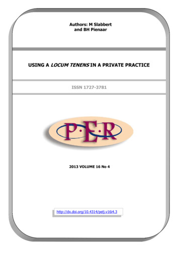
Reactor Concepts ManualPressurized Water Reactor SystemsSTEAMGENERATORNo. 2STEAMGENERATORNo. 1PUMPNo. 1BPUMPNo. 2APUMPNo. 1APUMPNo. 2BREACTORVESSELPRESSURIZERA Combustion Engineering plant has two steam generators, four reactor coolant pumps, and apressurizer. The Combustion Engineering units in the United States are Arkansas 2, Calvert Cliffs 1 and2, Fort Calhoun, Millstone 2, Palisades, Palo Verde 1, 2, and 3, San Onofre 2 and 3, Saint Lucie 1 and2, and Waterford 3. The electrical output of these plants varies from less than 500 to more than 1200megawatts.USNRC Technical Training Center4-80603
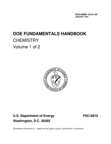
Reactor Concepts ManualPressurized Water Reactor SystemsReactor VesselThe reactor core, and all associated support and alignment devices, are housed within the reactor vessel(cutaway view on page 4-10). The major components are the reactor vessel, the core barrel, the reactorcore, and the upper internals package.The reactor vessel is a cylindrical vessel with a hemispherical bottom head and a removablehemispherical top head. The top head is removable to allow for the refueling of the reactor. There willbe one inlet (or cold leg) nozzle and one outlet (or hot leg) nozzle for each reactor coolant system loop.The reactor vessel is constructed of a manganese molybdenum steel, and all surfaces that come intocontact with reactor coolant are clad with stainless steel to increase corrosion resistance.The core barrel slides down inside of the reactor vessel and houses the fuel. Toward the bottom of thecore barrel, there is a lower core support plate on which the fuel assemblies sit. The core barrel and allof the lower internals actually hang inside the reactor vessel from the internals support ledge. On theoutside of the core barrel will be irradiation specimen holders in which samples of the material used tomanufacture the vessel will be placed. At periodic time intervals, some of these samples will beremoved and tested to see how the radiation from the fuel has affected the strength of the material.The upper internals package sits on top of the fuel. It contains the guide columns to guide the controlrods when they are pulled from the fuel. The upper internals package prevents the core from trying tomove up during operation due to the force from the coolant flowing through the assemblies.The flow path for the reactor coolant through the reactor vessel would be: The coolant enters the reactor vessel at the inlet nozzle and hits against the core barrel. The core barrel forces the water to flow downward in the space between the reactor vessel walland the core barrel. After reaching the bottom of the reactor vessel, the flow is turned upward to pass through the fuelassemblies. The coolant flows all around and through the fuel assemblies, removing the heat produced by thefission process. The now hotter water enters the upper internals region, where it is routed out the outlet nozzleand goes on to the steam generator.USNRC Technical Training Center4-90603
Reactor Concepts ManualPressurized Water Reactor SystemsROD TRAVELHOUSINGINSTRUMENTATIONPORTSCONTROL RODDRIVE MECHANISMTHERMAL SLEEVEUPPER SUPPORTPLATELIFTING LUGINTERNALSSUPPORTLEDGECLOSURE HEADASSEMBLYHOLD-DOWN SPRINGCORE BARRELCONTROL RODGUIDE TUBESUPPORT COLUMNCONTROL RODDRIVE SHAFTUPPER COREPLATEOUTLET NOZZLEINLET NOZZLEBAFFLE RADIALSUPPORTCONTROL RODCLUSTER (WITHDRAWN)BAFFLECORE SUPPORTCOLUMNSACCESS PORTINSTRUMENTATIONTHIMBLE GUIDESREACTOR VESSELRADIAL SUPPORTCORE SUPPORTLOWER CORE PLATECutaway View of Reactor VesselUSNRC Technical Training Center4-100603
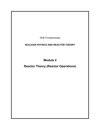
Reactor Concepts ManualPressurized Water Reactor SystemsSteam GeneratorsThe reactor coolant flows from the reactor to the steam generator. Inside of the steam generator, the hotreactor coolant flows inside of the many tubes. The secondary coolant, or feedwater, flows around theoutside of the tubes, where it picks up heat from the primary coolant. When the feedwater absorbssufficient heat, it starts to boil and form steam. At this point, the steam generators used by the threePressurized Water Reactor vendors differ slightly in their designs and operations.In the Westinghouse (page 4-12) and Combustion Engineering (page 4-13) designs, the steam/watermixture passes through multiple stages of moisture separation. One stage causes the mixture to spin,which slings the water to the outside. The water is then drained back to be used to make more steam.The drier steam is routed to the second stage of separation. In this stage, the mixture is forced to makerapid changes in direction. Because of the steam’s ability to change direction and the water’s inabilityto change, the steam exits the steam generator, and the water is drained back for reuse. The two stageprocess of moisture removal is so efficient at removing the water that for every 100 pounds of steam thatexits the steam generator, the water content is less than 0.25 pounds. It is important to maintain themoisture content of the steam as low as possible to prevent damage to the turbine blading.The Babcock & Wilcox design uses a once through steam generator (OTSG, page 4-14). In this design,the flow of primary coolant is from the top of the steam generator to the bottom, instead of through Ushaped tubes as in the Westinghouse and Combustion Engineering designs. Because of the heat transferachieved by this design, the steam that exits the once through steam generator contains no moisture.This is done by heating the steam above the boiling point, or superheating.Other differences in design include the ways in which the steam and the cooler primary coolant exit thesteam generators. In a Westinghouse steam generator, there is a single outlet for the steam and a singleoutlet for the primary coolant. For both the Babcock & Wilcox design and the Combustion Engineeringdesign there are two steam outlets and two primary coolant outlets.For all of the steam generator designs, the steam is piped to the main turbine, and the coolant is routedto the suction of the reactor coolant pumps.USNRC Technical Training Center4-110603
Reactor Concepts ManualPressurized Water Reactor SystemsSTEAM OUTLET TO TURBINEGENERATORDEMISTERS SECONDARYMOISTURE SEPARATORSECONDARYMANWAYORFICE RINGSSWIRL VANE PRIMARYMOISTURESEPARATORUPPER SHELLFEEDWATER INLETFEEDWATER RINGANTIVIBRATION BARSTUBE BUNDLELOWERSHELLWRAPPERTUBE SUPPORT PLATESBLOWDOWNLINESECONDARY HANDHOLETUBE SHEETTUBE LANEBLOCKPRIMARY MANWAYPRIMARY COOLANT INLETPRIMARY COOLANT OUTLETCutaway View of A Westinghouse Steam GeneratorUSNRC Technical Training Center4-120603
Reactor Concepts ManualPressurized Water Reactor SystemsSTEAMOUTLETDEFLECTOR126 STEAMDRYERSSTEAMDRUM166 STEAMSEPARATORS32 STEAMDRYER DRAINSSECONDARYMANWAY IONSUMPRECIRCULATIONSUMP DRAINSAUXILIARYFEEDWATERNOZZLEMAIN FEEDWATERNOZZLEMAIN FEED UBE BUNDLE)EGG CRATESUPPORTSVERTICLEU-TUBESSECONDARYHANDHOLE (2)BOTTOM BLOWDOWN& DRAIN NOZZLETUBESHEETCOLD LEGOUTLET (2)HOT LEGINLETCutaway View of a Combustion Engineering Steam GeneratorUSNRC Technical Training Center4-130603
Reactor Concepts ManualPressurized Water Reactor Systems36" INSIDE DIAMETER PRIMARY INLET NOZZLE16" INSIDE DIAMETERMANW AY(1) VENT & FULL RANGEUPPER INSTRUMENT TAP(6) EMERGENCYFEEDW ATER NOZZLES(2) 24" STEAMOUTLET NOZZLES(2) OPERATING ANDSTARTUP RANGEUPPER INSTRUMENT TAPS(32) FEEDW ATER INLETS14" OUTSIDE DIAMETERFEEDW ATER HEADERS(2) TEMP. SENSING CONNECTIONS(2) OPERATING RANGELOW LEVEL SENSINGCONNECTIONS(2) SAMPLING DRAINS16" INSIDE DIAMETER MANW AY(8) 3' 3/4" x 30" W ATER PORTS(2) STARTUP & FULL RANGELOW ER INSTRUMENT TAPS(4) 1-1/2"DRAIN16" INSIDE DIAMETER MANW AY1" DRAIN CONNECTION(2) 28" INSIDE DIAMETER PRIMARYOUTLET NOZZLESCutaway View of a Babcock & Wilcox Once Through Steam GeneratorUSNRC Technical Training Center4-140603
Reactor Concepts ManualPressurized Water Reactor SystemsReactor Coolant PumpThe purpose of the reactor coolant pump is to provide forced primary coolant flow to remove the amountof heat being generated by the fission process. Even without a pump, there would be natural circulationflow through the reactor. However, this flow is not sufficient to remove the heat being generated whenthe reactor is at power. Natural circulation flow is sufficient for heat removal when the plant isshutdown (not critical).The reactor coolant enters the suction side of the pump from the outlet of the steam generator. The wateris increased in velocity by the pump impeller. This increase in velocity is converted to pressure in thedischarge volute. At the discharge of the reactor coolant pump, the reactor coolant pressure will beapproximately 90 psi higher than the inlet pressure.After the coolant leaves the discharge side of the pump, it will enter the inlet or cold leg side of thereactor vessel. The coolant will then pass through the fuel to collect more heat and is sent back to thesteam generators.The major components of a reactor coolant pump (page 4-16) are the motor, the hydraulic section, andthe seal package.The motor is a large, air cooled, electric motor. The horsepower rating of the motor will be from 6,000to 10,000 horsepower. This large amount of power is needed in order to provide the necessary flow ofcoolant for heat removal (approximately 100,000 gallons per minute per pump).The hydraulic section of the pump is the impeller and the discharge volute. The impeller of the pumpis attached to the motor by a long shaft.The seal package is located between the motor and the hydraulic section and prevents any water fromleaking up the shaft into the containment atmosphere. Any water that does leak up the shaft is collectedand routed to the seal leakoff system for collection in various systems.USNRC Technical Training Center4-150603
Reactor Concepts ManualPressurized Water Reactor SystemsFLYWHEELUPPER RADIALBEARINGTHRUST BEARINGMOTOR SHAFTTHRUST BEARINGOIL LIFT PUMP MOTORMOTOR STATORMAIN LEADCONDUIT BOXMOTOR UNIT ASSEMBLYLOWER RADIALBEARINGSEAL HOUSINGNO. 3 SEALLEAK OFFNO. 1 SEAL LEAK OFFNO. 2 SEALLEAK OFFMAIN FLANGECOOLING WATEROUTLETPUMP SHAFTCOOLANT WATER INLETRADIAL BEARINGASSEMBLYDISCHARGENOZZLETHERMAL BARRIER ANDHEAT EXCHANGERCASINGSUCTIONNOZZLEIMPELLERCutaway View of a Reactor Coolant PumpUSNRC Technical Training Center4-160603
Reactor Concepts ManualPressurized Water Reactor SystemsPressurizerThe pressurizer (page 4-18) is the component in the reactor coolant system which provides a means ofcontrolling the system pressure. Pressure is controlled by the use of electrical heaters, pressurizer spray,power operated relief valves, and safety valves.The pressurizer operates with a mixture of steam and water in equilibrium. If pressure starts to deviatefrom the desired value, the various components will actuate to bring pressure back to the normaloperating point. The cause of the pressure deviation is normally associated with a change in thetemperature of the reactor coolant system. If reactor coolant system temperature starts to increase, thedensity of the reactor coolant will decrease, and the water will take up more space. Since the pressurizeris connected to the reactor coolant system via the surge line, the water will expand up into thepressurizer. This will cause the steam in the top of the pressurizer to be compressed, and therefore, thepressure to increase.The opposite effect will occur if the reactor coolant system temperature decreases. The water willbecome more dense, and will occupy less space. The level in the pressurizer will decrease, which willcause a pressure decrease. For a pressure increase or decrease, the pressurizer will operate to bringpressure back to normal.For example, if pressure starts to increase above the desired setpoint, the spray line will allow relativelycold water from the discharge of the reactor coolant pump to be sprayed into the steam space. The coldwater will condense the steam into water, which will reduce pressure (due to the fact that steam takesup about six times more space than the same mass of water). If pressure continues to increase, thepressurizer relief valves will open and dump steam to the pressurizer relief tank. If this does not relievepressure, the safety valves will lift, also discharging to the pressurizer relief tank.If pressure starts to decrease, the electrical heaters will be energized to boil more water into steam, andtherefore increase pressure. If pressure continues to decrease, and reaches a predetermined setpoint, thereactor protection system will trip the reactor.The pressurizer relief tank (page 4-19) is a large tank containing water with a nitrogen atmosphere. Thewater is there to condense any steam discharged by the safety or relief valves. Since the reactor coolantsystem contains hydrogen, the nitrogen atmosphere is used to prevent the hydrogen from existing in apotentially explosive environment.USNRC Technical Training Center4-170603
Reactor Concepts ManualPressurized Water Reactor SystemsSPRAY NOZZLESAFETY NOZZLERELIEFNOZZLEMANWAYUPPER HEADINSTRUMENTATIONNOZZLELIFTINGTRUNNION(LOAN BASIS)SHELLLOWER HEADHEATER SUPPORTPLATEINSTRUMENTATIONNOZZLEELECTRICAL HEATERSUPPORT SKIRTSURGE NOZZLECutaway View of a PressurizerUSNRC Technical Training Center4-180603
Reactor Concepts ManualPressurized Water Reactor YPRESSURIZERHEATERSVENTSURGE LINEPRESSURIZERRELIEF TANKREACTOR COOLANTSYSTEM (RCS)DRAINPressurizer and Pressurizer Relief TankUSNRC Technical Training Center4-190603
Reactor Concepts ManualPressurized Water Reactor SystemsCONTAINMENTMOISTURE SEPARATORREHEATER (MSR)SAFETYVALVESTHROTTLEVALVEMAIN STEAMISOLATION CORELPHEATERREACTOR COOLANTSYSTEMRCPCLEAN UPSYSTEMMAINFEEDWATERPUMPCONDENSATEPUMPCONTAINMENT SUMPThe major secondary systems of a pressurized water reactor are the main steam system and thecondensate/feedwater system. Since the primary and secondary systems are physically separated from each other(by the steam generator tubes), the secondary system will contain little or no radioactive material.The main steam system starts at the outlet of the steam generator. The steam is routed to the high pressure mainturbine. After passing through the high pressure turbine, the steam is piped to the moisture separator/reheaters(MSRs). In the MSRs, the steam is dried with moisture separators and reheated using other steam as a heatsource. From the MSRs, the steam goes to the low pressure turbines. After passing through the low pressureturbines, the steam goes to the main condenser, which is operated at a vacuum to allow for the greatest removalof energy by the low pressure turbines. The steam is condensed into water by the flow of circulating waterthrough the condenser tubes.At this point, the condensate/feedwater system starts. The condensed steam collects in the hotwell area of themain condenser. The condensate pumps take a suction on the hotwell to increase the pressure of the water. Thecondensate then passes through a cleanup system to remove any impurities in the water. This is necessarybecause the steam generator acts as a concentrator. If the impurities are not removed, they will be left in thesteam generator after the steam forming process, and this could reduce the heat transfer capability of the steamgenerator and/or damage the steam generator tubes. The condensate then passes through some low pressurefeedwater heaters. The temperature of the condensate is increased in the heaters by using steam from the lowpressure turbine (extraction steam). The condensate flow then enters the suction of the main feedwater pumps,which increases the pressure of the water high enough to enter the steam generator. The feedwater now passesthrough a set of high pressure feedwater heaters, which are heated by extraction steam from the high pressureturbine (heating the feedwater helps to increase the efficiency of the plant). The flow rate of the feedwater iscontrolled as it enters the steam generators.USNRC Technical Training Center4-200603
Reactor Concepts ManualPressurized Water Reactor SystemsCOOLING WATERCONTAINMENTREGENERATIVEHEAT EXCHANGERDEMINERALIZERTANKSFLETDOWN ANKPUREWATERTANKBORICACIDTANKPURE WATERTRANSFER PUMPRCP SEALINJECTIONREACTOR COOLANTSYSTEMRCPCHARGINGPUMPBORIC ACIDTRANSFER PUMPCONTAINMENT SUMPThe chemical and volume control system (CVCS) is a major support system for the reactor coolantsystem. Some of the functions of the system are to: Purify the reactor coolant system using filters and demineralizers,Add and remove boron as necessary, andMaintain the level of the pressurizer at the desired setpoint.A small amount of water (about 75 gpm) is continuously routed through the chemical and volumecontrol system (called letdown). This provides a continuous cleanup of the reactor coolant system whichmaintains the purity of the coolant and helps to minimize the amount of radioactive material in thecoolant.The reactor coolant pump seals prevent the leakage of primary coolant to the containment atmosphere.The chemical and volume control system provides seal injection to keep the seals cool and providelubrication for the seals. This water has been cooled by the heat exchangers and cleaned by the filtersand demineralizers.There is also a path (not shown) to route the letdown flow to the radioactive waste system for processingand/or disposal.USNRC Technical Training Center4-210603
Reactor Concepts ManualPressurized Water Reactor SystemsTOATMOSPHERECONTAINMENTSTEAM TOMAIN TURBINEFEEDWATER FROMMAIN TOR COOLANTSYSTEMRCPAUXILIARYFEEDWATERPUMPCONTAINMENT SUMPDuring normal operation, the heat produced by the fission process is removed by the reactor coolant andtransferred to the secondary coolant in the steam generators. Here, the secondary coolant is boiled into steamand sent to the main turbine.Even after the reactor has been shutdown, there is a significant amount of heat produced by the decay of fissionproducts (decay heat). The amount of heat produced by decay heat is sufficient to cause fuel damage if notremoved. Therefore, systems must be designed and installed in the plant to remove the decay from the core andtransfer that heat to the environment, even in a shutdown plant condition. Also, if it is desired to performmaintenance on reactor coolant system components, the temperature and pressure of the reactor coolant systemmust be reduced low enough to allow personnel access to the equipment.The auxiliary feedwater system and the steam dump system (turbine bypass valves) work together to allow theoperators to remove the decay heat from the reactor. The auxiliary feedwater system pumps water from thecondensate storage tank to the steam generators. This water is allowed to boil to make steam. The steam canthen be dumped to the main condenser through the steam dump valves. The circulating water will then condensethe steam and take the heat to the environment.If the steam dump system is not available (for example, no circulating water for the main condenser), the steamcan be dumped directly to the atmosphere through the atmospheric relief valves.By using either method of steam removal, the heat is being removed from the reactor coolant system, and thetemperature of the reactor coolant system can be reduced to the desired level.USNRC Technical Training Center4-220603
Reactor Concepts ManualPressurized Water Reactor SystemsTOENVIRONMENTCONTAINMENTSERVICE WATERSYSTEM(SW)CCW HEATEXCHANGERFROMENVIRONMENTSWPUMPS/GPZRCOMPONENT COOLINGWATER SYSTEM(CCW)CCWPUMPRHR HEATEXCHANGERCOREREACTOR COOLANTSYSTEMRHRPUMPRESIDUAL HEATREMOVAL SYSTEM(RHR)RCPCONTAINMENT SUMPAt some point, the decay heat being produced will not be sufficient to generate enough steam in thesteam generators to continue the cooldown. When the reactor coolant system pressure and temperaturehave been reduced to within the operational limits, the residual heat removal system (RHR) will be usedto continue the cooldown by removing heat from the core and transferring it to the environment.This is accomplished by routing some of the reactor coolant through the residual heat removal systemheat exchanger, which is cooled by the component cooling water system (CCW). The heat removed bythe component cooling water system is then transferred to the service water system in the componentcooling water heat exchanger. The heat picked up by the service water system will be transferreddirectly to the environment from the service water system.The residual heat removal system can be used to cool the plant down to a low enough temperature thatpersonnel can perform any maintenance functions, including refueling.USNRC Technical Training Center4-230603
Reactor Concepts ManualPressurized Water Reactor SystemsEmergency Core Cooling SystemsThere are two purposes of the emergency core cooling systems (ECCS). The first is to provide corecooling to minimize fuel damage following a loss of coolant accident. This is accomplished by theinjection of large amounts of cool, borated water into the reactor coolant system. The second is toprovide extra neutron poisons to ensure the reactor remains shutdown following the cooldown associatedwith a main steam line rupture, which is accomplished by the use of the same borated water source. Thiswater source is called the refueling water storage tank (RWST).To perform this function of injection of large quantities of borated water, the emergency core coolingsystems consist of four separate systems (page 4-25). In order of highest pressure to lowest pressure,these systems are: the high pressure injection (or charging) system, the intermediate pressure injectionsystem, the cold leg accumulators, and the low pressure injection system (residual heat removal). Eventhough the diagram shows only one pump in each system, there are actually two, each of which iscapable of providing sufficient flow. Also, these systems must be able to operate when the normalsupply of power is lost to the plant. For this reason, these systems are powered from the plant emergency(diesel generators) power system.The high pressure injection system uses the pumps in the chemical and volume control system. Uponreceipt of an emergency actuation signal, the system will automatically realign to take water from therefueling water storage tank and pump it into the reactor coolant system. The high pressure injectionsystem is designed to provide water to the core during emergencies in which reactor coolant systempressure remains relatively high (such as small break in the reactor coolant system, steam breakaccidents, and leaks of reactor coolant through a steam generator tube to the secondary side).The intermediate pressure injection system is also designed for emergencies in which the primarypressure stays relatively high, such as small to intermediate size primary breaks. Upon an emergencystart signal, the pumps will take water from the refueling water storage tank and pump it into the reactorcoolant system.The cold leg accumulators do not require electrical power to operate. These tanks contain large amountsof borated water with a pressurized nitrogen gas bubble in the top. If the pressure of the primary systemdrops below low enough, the nitrogen will force the borated water out of the tank and into the reactorcoolant system. These tanks are designed to provide water to the reactor coolant system duringemergencies in which the pressure of the primary drops very rapidly, such as large primary breaks.The low pressure injection system (residual heat removal) is designed to inject water from the refuelingwater storage tank into the reactor coolant system during large breaks, which would cause a very lowreactor coolant system pressure. In addition, the residual heat removal system has a feature that allowsit to take water from the containment sump, pump it through the residual heat removal system heatexchanger for cooling, and then send the cooled water back to the reactor for core cooling. This is themethod of cooling that will be used when the refueling water storage tank goes empty after a largeprimary system break. This is called
Robinson 2, North Anna 1 and 2, Shearon Harris 1, V. C. Summer, Surry 1 and 2, and Turkey Point 3 and 4. Each of these plants has 157 fuel assemblies. Some units use 15 x 15 fuel assemblies while others use 17 x 17 arrays. The reactor ves