Transcription
AN INTRODUCTION TOTIGWELDINGwws group support@weldability.comWARNING:This document contains general information about the topic discussed herein. This document is not anapplication manual and does not contain a complete statement of all factors pertaining to that topic.The installation, operation and maintenance of arc welding equipment and the employment of proceduresdescribed in this document should be conducted only by qualified persons in accordance with applicablecodes, safe practices, and manufacturers’ instructions.Always be certain that work areas are clean and safe and that proper ventilation is used. Misuse ofequipment, and failure to observe applicable codes and safe practices can result in serious personalinjury and property damage.www.weldability.com
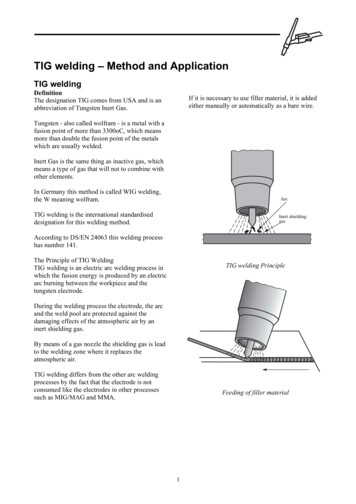
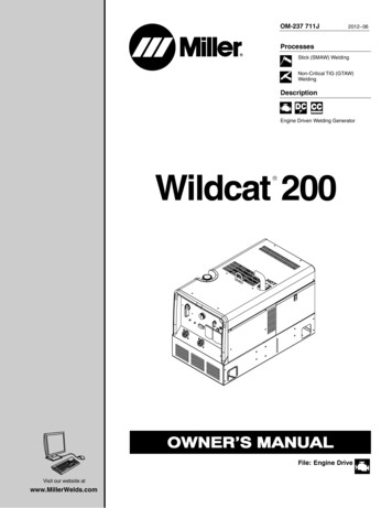
an introduction to TIG weldingGeneral PrinciplesTIG (Tungsten Inert Gas) welding also known as GTA (Gas Tungsten Arc) in the USA and WIG (Wolfram Inert Gas)in Germany, is a welding process used for high quality welding of a variety of materials, especially, Stainless Steel,Titanium and Aluminium.Equipment DC or AC / DC Power SourceTIG TorchWork Return Welding LeadShielding gas supply line, ( normally from a cylinder )Foot Control Unit ( common option )Power SourceTIG welding can be carried out using DC for Stainless Steel, Mild Steel, Copper,Titanium, Nickel Alloys etc and AC for Aluminium and its Alloys and Magnesium.Further information on the TIG Welding Process follows information on equipmentused in this document.The Power Source is of a transformer design with or without a rectifier, with adrooping characteristic (constant current power source).The output is generally controlled by either a moving core within the maintransformer of the power source or by using electronic control of power thyristors.a typical TIG welding setupDC power sources could be of 1 phase or 3 phase design, with an inductor to provide a smooth output. AC and AC /DC Power Sources are of a single phase design.Other important functions in TIG power sources are Arc Starting Circuitvolt-amp curve of a typicalconstant-current power source.HF : - Sparks of high tension jumpacross the gap between electrode andworkpiece rapidly to carry the weldingcurrent across to start welding in DCTIG welding, this will stop once the arcis struck, in AC TIG welding, this willnormally continue to keep the arc aliveas the AC output changes from aPositive half cycle to a Negative halfcycle and back again.Lift Arc : - The electrode is touched onto the workpiece, the TIG Torch switch orfoot control switch is operated, the equipment circuits detect a short circuit on theoutput and allow only a very low current typically 5 - 8 amps to flow. Theelectrode is lifted off the workpiece, the equipment circuits now detect a voltagebetween electrode and workpiece and welding current strikes across that verytiny gap as the electrode lifts off and welding continues.Scratch Start : - The electrode is scratched or dragged and lifted off theworkpiece, much the same as striking an electrode in MMA ( Stick ) welding.Using the HF method. No cross contamination from electrode and workpiecetakes place as they never touch, with Lift arc correctly set and used, only minimalcross contamination occurs because of the low current when electrode is incontact with workpiece, scratch start TIG is a low cost option for general TIGwelding, but cross contamination can occur.principle of rectification of alternating currentpage 2 of 8www.weldability.com support@weldability.com
an introduction to TIG weldingOutput ControlIn TIG output voltage is not controlled by the power source ( as with MIG ), but is determined by the process andoutput welding current. Welding current is normally controlled by either a moving core in the main transformer or byelectronic power components.Moving Core Control : - The main drawback of this method of control, is its slow response to change whenrequired and due to the mechanical movement remote controls ( such as foot control ) are so difficult andexpensive to provide, that it is thought of as not possible.Electric Power Control : - This system has many advantages over the previous system. The possibility to have aremote control of welding current, so the operator can raise or lower the output as required while welding.Craterfil / Slopedown ControlIf not using a remote control, but simply a torch ON / OFF switch the output can be sloped down to finish theweld without a crater at the end of the molten pool, an electronic timer gradually reduces the output from weldingvalve to off over an adjustable time.AC Waveform BalanceA pot can be fitted, when welding in AC mode the positive half cycle cleans the oxides on the Aluminium and theNegative half cycle produces weld penetration during welding self rectification occurs and causes an imbalance ofthe waveform, a balance control allows the operator to adjust the amount of time the cleaning or penetration takes ineach cycle.Gas Flow ControlThe TIG process relies entirely on the shielding gas to protectthe hot electrode and molten pool and it is therefore essentialfor good arc striking that the flow of gas is initiated and allowedto stabilise before the arc is struck. Preflow timers arecommonly fitted to better TIG power sources.Equally the gas shield must be allowed to flow after the arc isextinguished, to prevent oxidation of the electrode and coolingweld. Postflow timers are fitted to most TIG power sources.the effects of altering the AC wave-form balanceDC Output Pulse ControlFor DC welding use, there is often a pulsing facility which allows the welding current to be switched between a lowcurrent ( say approximately 15 amps ), sufficient to keep the arc alight but not produce much heat and the main pulsecurrent ( say 50 - 350 amps ), dependant on the design control of the following parameters can be adjusted to providehigh quality welding.Peak Current ValvePeak TimeBase Current ValveBase Current TimeFrequency of PulsesThe use of pulsed current greatly extends the control which can be exercised on the process allowing:****Improved consistency in the under head of unbacked butt welds.The ability to overcome differences in heat sink and therefore to join thick to thin material.The ability to make cylindrical or circular welds without a build up of heat and an increase in weld width.The ability to produce stable TIG welds at very low level.Basically a series of overlapping spot welds, with short cooling periods between such welds.page 3 of 8www.weldability.com support@weldability.com
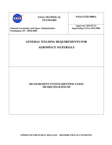
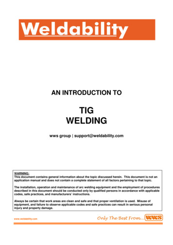
an introduction to TIG weldingTIG TorchThe TIG torch can be air cooled or water cooled and of vastly different shapes and sizes dependant on access to thearea to be welded and welding current required.TIG torch for use on equipment without a electric operated valve ( normally scratch start systems ) can have a fingeroperated gas valve fitted to the torch head.If the operator is using a foot control unit, the torch will not need a switch fitted. For welding in difficult to get to areas,a flexible head torch can be used and bent to the best position for welding.In water cooled torches, the current cable is a bore copper conductor within a water carrying hose, this means theconductor can be greatly reduced in size and weight.The gas shield are now invariably alumina ceramics and are available in a wide range of sizes.When access is difficult, it may be necessary to project the electrode well beyond the end of the gas nozzle, this mayresult in inferior gas shielding because of turbulence. This can usually be overcome by employing a Gas Lens Systemreplacing the standard collet and collet body system, this producing improved directional and stability of the gas flow.Connection to the power source can be via a special lug if the equipment has a stud output fitting, or a universal dinsetype TIG adaptor if output fittings are dinse type sockets.Electrodes for TIG welding are Pure Tungsten or a Tungsten oxide, generally 2 % Thoriated tungsten are used for DCwelding and 2 % Zirconiated tungsten are recommended for AC welding. The diameter of the electrode is chosen tomatch the current required.For DC welding, a sharp point is required but for AC welding only, a small bevel is needed as the end of the electrodebecomes rounded when the arc is operated.Shielding GasThe most commonly used gas for TIG welding is argon which can be used on all metals. Argon - Hydrogen mixturescontaining 2 - 5 % Hydrogen are frequently used for stainless steel and nickel-base alloys having the advantage ofproducing cleaner welds, giving deeper penetration.Helium - Argon mixtures give deeper penetration, greater heat input and therefore faster welding because of thehigher arc voltage than pure Argon, but arc striking may be more difficult than in Argon. These mixtures can be usedfor Aluminium and Copper Alloys.Welding Processthe principle features of TIG weldingIn most Arc welding processes, the arc is struck from aconsumable electrode to the workpiece and metal hasbeen melted from electrode, transferred across the arcand finally incorporated into the molten pool. TIG processemploys on electrode made from high melting pointmetal, usually a type of TUNGSTEN, which is not melted.The electrode and the molten pool is shielded from theatmosphere by a stream of inert gas which flows aroundthe electrode and is directed onto the workpiece by anozzle which surrounds the electrode.In TIG welding, the primary functions of the arc is to supply heat to melt the workpiece and any filler metal which maypage 4 of 8www.weldability.com support@weldability.com
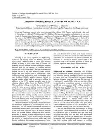
an introduction to TIG weldingbe necessary. This filler metal is fed manually into the molten pool at its leading edge.The second function of the arc is to clean the surface of the molten pool and the immediately surrounding parentmetal of surface oxide films and therefore no flux is required.The shielding gas MUST be inert with respect to the tungsten electrode and the choice is therefore more limited thanwith the MIG process.When using DC the DCEN electrode negative polarity is almost invariably employed, ( if DCEP is used most of theheat is in the electrode not the workpiece, so if this polarity is used, very much larger electrodes MUST be used ).The cleaning function of the arc does not take place on the DCEN polarity, so metals forming refractory oxide surfacefilms such as aluminium cannot be readily welded on this polarity.For Aluminium the electrode positive polarity on which cleaning takes place, would therefore appear desirable. In facton this polarity, more energy is dissipated at the electrode which therefore becomes overheated.Aluminium is therefore welded using AC and the cleaning action takes place on the electrode positive half cycles andweld penetration takes place on the electrode negative half cycle.Zirconiated tungsten electrodes are used for AC welding because Zirconia helps the electrode to maintain the desiredstable end.Optimum Process VariablesTungstenTIG ProcessSuitable Metals1 – 2% Thoriated TungstensUsed mainly in DCEN, but possiblewith DCEP.Ferrous materials and some non-ferrous,excluding aluminium and magnesium.Zirconiated TungstensUsed mainly in AC, but possible inDC with DCEN or DCEP.Aluminium, magnesium and alloys ofthese materials.Maximum Tungsten Current RatingsElectrode um Current-Carrying Capacity 410500-B. S Recommendations for Class 1Welds.ZirconiatedA.C (With Suppressor)5080120160200250320-Optimum Tungsten Current Ratingspage 5 of 8www.weldability.com support@weldability.com
an introduction to TIG weldingOptimum Current Ranges – In AmpsDiameter (in)Diameter (mm)DCSP ArgonDCRP ArgonACHF ArgonAC 0-6060-120100-180160-250200-320290-390340-5252% THORIUM ALLOYED 60135-235250-400400-500500-750750-1000Optimum Current Ranges – In AmpsDiameter (in)Diameter (mm)DCSP ArgonDCRP ArgonACHF ArgonAC 0290-390340-525ZIRCONIUM ALLOYED /16”1/4”0.51.01.62.43.24.04.86.4-Selection of Welding Variables for Specific Joint PreparationsMaterialStainless,heat e OfPowerArgon 0130d.c or a.cd.c or a.cd.c or 34.74.75.06.07.04.8130170Aluminium 30150150200Electrode Dia.(mm)1.6 or2.41.6 or2.42.42.4 or3.22.4 or3.23.22.42.43.23.23.24.8NozzleBore(mm)610101010 or 12No. ofPassesPrep Type(see below)1111110 or 121S.E.C.BS.E.C.BS.E.C.BS.E.C.BS.E.O.B orS.V.C.B 80ES.V.C.B .E.C.BS.E.C.BSelection of Welding Variables TIG Welding Mild Steelpage 6 of 8www.weldability.com support@weldability.com
an introduction to TIG weldingMILD STEEL -- MANUAL WELDING -- DIRECT CURRENT -- DCEN POLARITYMetalThicknessJoint TungstenDiameterFiller 0202020202020ArgonArgonArgonArgonSelection of Welding Variables TIG Welding Stainless SteelSTAINLESS STEEL -- MANUAL WELDING -- DIRECT CURRENT -- DCEN POLARITYMetalThickness1.6mm3.2mm4.8mm6.3mmJoint er 5151515151515152020202020202020Selection of Welding Variables TIG Welding Aluminiumpage 7 of 8www.weldability.com support@weldability.com
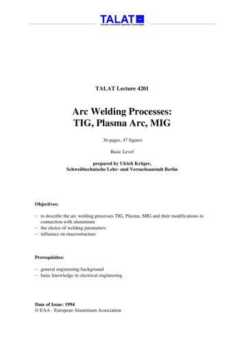
an introduction to TIG weldingALUMINIUM -- MANUAL WELDING -- ALTERNATING CURRENT -- HIGH FREQUENCYMetalThickness1.6mm3.2mm4.8mm6.3mmJoint er 20Visual Reference Of Joint Preparation TypesFor use with above welding variable tablespage 8 of 8www.weldability.com support@weldability.com
welding and 2 % Zirconiated tungsten are recommended for AC welding. The diameter of the electrode is chosen to match the current required. For DC welding, a sharp point is required but for AC welding only, a small bevel is needed as the end of the electrod