Transcription
Welder Guide BookOK AristoRod non copper-coated solid MAG wireswith Advanced Surface CharacteristicsSTRENGTH THROUGH COOPERATION
ContentsIntroduction 3Before you start welding - checklist 4 Contact tip and gas nozzle 4 Contact tip size, liner size and wire diameter 4 Liner 5 Gas and water 5 Wire feed unit 5 ESAB Marathon Pac installation 6 Drive rolls and wire feeding 8 Shielding gas 9Contact tip and gas nozzle 10Welding parameter setting 1214OK AristoRodTM product range SATTM process 15Don't miss out the interesting OK AristoRod microsite. It explains whyOK AristoRod wires bring trouble-free, high productivity welding inrobotised, mechanised or manual operation supported by unique videoanimation in 24 languages, scientific data and high speed arc recording.It discusses quality and productivity benefits in detail and reviews the fullrange of wire types for non- and low-alloyed steels.www.esab.com/aristorod2
IntroductionOK AristoRod is a family of non copper-coated MAG wires withsuperior welding performance. OK AristoRod unique AdvancedSurface Characteristics (ASC) gives the user higher performance andefficiency no matter if it is manual, mechanised or robotic MAGwelding. OK AristoRod therefore has a positive impact on reducingoverall welding costs. ESAB's unique ASC has enabled the creation ofa family of non-copper-coated wires which do not contaminate wirefeeders, liners, torches and contact tips with copper particles. Thisresults in trouble free feeding, a high process stability, reducedconsumption of wear parts and superior welding properties.ESAB OK AristoRod has a number of unique features. Thesetranslate into clear end user benefits which, together, add up toincreased productivity and lower welding costs.FeatureConsistent weldingperformanceBenefitConsistent weld resultsStable arc with low feedingforceExcellent arc ignitionHigh weld quality. Reducedrework or post weld cleaningHigh current operabilityHigher productivityExtremely low spatter levelReduced post weld cleaningReduced post weld cleaningTrouble-free feedability, even Higher productivity, reducedat high wire feed speeds and equipment downtimelong feed distancesLow fume emissionCleaner working environmentIn order to benefit the most from using AristoRod MAG wires,there are some important steps to keep in mind, in particularcompared to using copper-coated wires. This guide providespractical step-by-step information on how to install and use ofAristoRod non copper-coated solid wires.3
Before you start weldingTo fully benefit from the excellent weldability of OK AristoRod MAG wires, the welding equipment needs to be maintained ingood condition. The following checklist serves as a guide.CHECKLISTContact tips and gas nozzle Remove spatter and replaceworn or damaged contact tip. For the best weldingperformance and longest tiplife, ESAB AristoTip contacttips are recommended for usewith AristoRod wires. Grind the end of the linerconical for optimal fitting of thecontact tip (ESAB M8). Ensure that the contact tip isthe correct size and fits tightly. Ensure the gas nozzle is freefrom spatter.incorrectWire diameter(mm)DescriptionESAB item nr.1.0AristoTip 1.0M8/10/30mm07003003012001.2AristoTip 1.2M8/10/30mm07003003032001.4AristoTip 1.4M8/10/30mm0700300305200For additional sizes, contact ESAB.4correctPieces/box
Liner Spiral steel liners arerecommended. Never use liners which havebeen used for copper-coatedwires. Copper residuals maystick onto the AristoRod wire and deteriorate it isexcellent wire feeding. Ensure that the liner has thecorrect inner diameter for thewire size to be used. Check liners regularly for kinksand excessive wear andreplace when needed. Clean liners regularly usingcompressed air. Firstlyremove contact tip.Gas and water Check gas and waterconnections for leaks. Check if water cooler is filledand pump operatessatisfactorily.Wire feed unit Position wire guide tubes asclose as possible to therollers to prevent kinking ofthe wire.A substantial amount of finemetallic shavings underneaththe drive rolls indicatesmisalignment.CorrectIncorrect5
Before you start weldingESAB Marathon Pac installationESAB Marathon Pac is themost advanced bulk wirepackaging system available tofabricators. The completeMarathon Pac family consistsof (from left to right) : Endless Marathon Pac Mini Marathon Pac Standard Marathon Pac Jumbo Marathon Pac ESAB MarathonPac iscompleted by a full range ofaccessories for efficient internaltransport and handling and foreasy installation.Always make sure ESAB originalMarathon Pac accessories*are used for best performance.*For a complete list of Marathon Pacaccessories, contact ESAB.Original lifting yoke to handle thedrum safely and to not damage thedrum or wire.6Special cone for Jumbo MarathonPac with 475kg non- or lowalloyed wire.
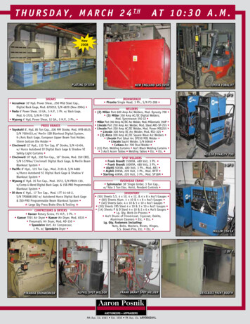
Step 1. Remove the rubber strapand VCI paper.Step 2. Place the wire conduitattachment or “spider” on top of theMarathon Pac .Step 3. Feed the welding wirethrough the centre of the spider.Step 4. Place the carton or plastic lid(Standard and Mini Marathon Pac )or cone (Jumbo Marathon Pac ).Step 5. Attach the wire conduit tothe lid or cone with the quickconnector.Step 6. Attach the wire conduit to thewire feeder. Avoid liner bends or pointpressure on the liner.7
Before you start weldingCheck drive rolls and wire feeding Use drive rolls with smooth,double V-grooves. U-shapedgrooves or knurled rolls maydamage the AristoRod wiresurface. Check that the groove size iscorrect for the wire diameter.Smooth Apply the correct pressure onfeed rolls. Too much pressureflattens the wire, resulting infeedings problems and higherliner and contact tip wear.Insufficient pressure may causewire to slip in the feed rolls,resulting in irregular feeding andpossible wire burnback. A good approach is to set theroll pressure such that it ispossible to stop a bend wire atthe gas nozzle by applying alight pressure. Check that the wire is feedingcorrectly from the contact tip. Never use felt pads or liquidsto clean the wire surface. Thismay damage the advancedsurface condition of OKAristoRod wires.8Knurled
Shielding gas Check that the appropriate gasis used. Adjust gas flow rateto between 15-20 l/min oraccording to gas nozzle size. Check the gas flow rate againif the gas nozzle diameter ischanged.Always check the gas flowon the gas nozzle too.9
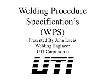
Contact tip and gas nozzle2 mmCorrect positioning of contact tip.Incorrect. Contact tip too recessed.Incorrect. Contact tip protrudingbeyond gas nozzle.12-20mmIdeal stick-out for wire diameters1.0 and 1.2 mm.10It is essential to fit the gasnozzle and contact tip at theright distance relative to eachother. The ideal distance of thecontact tip is 2 mm recessed.A longer distance will force thewelder to use too long a stickout, resulting in poor weldability.This may lead to lack of fusion,particularly in narrow joints.Contact tips protruding beyondthe gas nozzle can result ininsufficient gas shielding.Correct stick-out lengthThe stick-out is the distancebetween the contact tip andworkpiece and must be keptbetween 12 and 20 mm(ø1.0 and 1.2 mm). Excessivestick-out results in a too shortarc length, larger droplets, anunstable arc and spatter, sopoor weldability. Additionally, itmay reduce the gas protectionwhich can lead to porosity.When welding in spray arc withtoo short a stick-out, the arclength can become too long.The weldpool will get hotter andmore difficult to control.
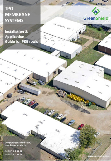
When welding in short arctransfer, the arc stability andstart properties will improvewhen reducing the stick-out.Gas nozzle diameterVarious nozzle diameters mustbe available to allow satisfactoryaccess to the joint, to maintainthe above recommended stickout, and to ensure propershielding gas protection. Smalldiameter gas nozzles are usedfor the first layers only. Revert tothe standard gas nozzlediameter when access to theweld joint allows this, so full gasprotection can be assured.12-20mmCorrect. Use a smaller diameternozzle or a conical nozzle for the1st layers in the root area.20mmIncorrect. Use of standard gasnozzle restricts access to narrowjoints, resulting in too long astick-out.Correct. Use of standard gas nozzlefor completing the joint ensuresgood gas protection and correctstick-out.11
Welding parameter settingUse positive polarity for OKAristoRodTM solid wires. A givenwelding current requires a specificarc voltage for optimum weldability.The welding current is set byadjusting the wire feed speedcontrol. The arc voltage isregulated by the open circuitvoltage (OCV) setting of the powersource.Correct. Correct arc length. Stableand concentrated arc with a quietspray droplet transfer.How to get an optimum setting?For the following procedure, it isvitally important to keep the stickout constant within the correctrange for each welding position. Select a welding current (I)which suits your applicationfrom the figure on page 13.Incorrect. Arc length too short. Wiredips into weld pool (stubbing) causedby too low an arc voltage, too high awire speed or too long a stick-out. Start welding with the lowestvoltage value from the givenrange. This may result instubbing, however wireburnback will be avoided. Increase the arc voltage in stepsof 1 or 2 V, until the arcbecomes stable, smooth andspatter free, with a slightlycrackling sound. Ensure thecorrect stick-out length ismaintained.12Incorrect. Arc length too long. Arcbecomes too wide, giving insufficientpenetration. Also a risk of burnback tothe contact tip. This may be causedby the arc voltage being too high, thewire feed speed too low or the stickout being too short.
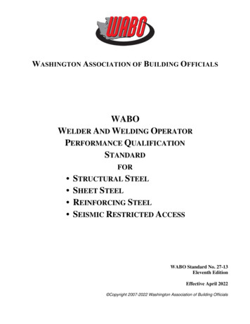
NOTE: As mentioned, stick-outcontrol is very important. If therecommended stick-out length isnot maintained constant,weldability will fluctuate.Shortening the stick-out willresult in an increasing currentand a longer arc. Lengtheningthe stick-out will result in a lowercurrent and the arc being tooshort. Due to AristoRod’s advancedsurface characteristics theoptimal voltage is typically5-10% higher than with acopper-coated wire at thesame arc length. If a different current isrequired, i.e change ofwelding position, theprocedure described on theprevious page needs to berepeated.OK AristoRod OK AristorodTM1Welding in short arc area. Use for thin plate, tack weldingor positional welding.1.0 mm2Welding in globular area. Unstable arc and excessive spatter.Try to avoid.1.2 mm3Welding in spray arc transfer. High productivity,thick plate, downhand welding, low spatter.4Excessive weld metal. Difficult to control.384363343230Voltage28226242220When arc length is tooshort increase voltage.118When arc length is toolong decrease voltage.16141250100150200250300350400Amperage13
R120S-GER120S-G13.0913.1213.1613.2213.2655 (13.13)69 (13.29)79 (13.31)89 (1B96)G Z 3Ni1CuG2MoER80S-D2 ISO14341-AA5.18A5.28AWSG Mn4Ni2CrMoG Mn4Ni2CrMoG Mn3Ni1CrMoG Mn3NiCrMo16834-AG CrMo2Si / G 62M 2C1M3Z CrMo1Si / G 55A 1CMG CrMo1Si / G 55M 1CM3G MoSi /G 1M321952-A /-BOK AristoRod Classification wire Classification wire and weld metalAWS and EN classificationsG 89 4G 79 4G 69 4G 55 4G 46 4G 46 2G 50 4G 46 4G 46 4G 46 4G 38 3G 42 4M21G 42 0G 38 0G 46 0G 42 2G 42 2G 42 3G 35 2G 38 2C1EN-ISO 14175High strengthHigh strengthHigh strengthHigh strengthWeather resistantCreep resistantCreep resistantCreep resistantCreep resistantCreep resistantNormal strengthNormal strengthNormal strengthNormal strengthNormal strengthShielding gas Steel typeOK AristoRod – the complete range
ESAB Swift Arc Transfer arcMixedarcSpray arctingRotaarcShortArc voltageThe ultimate high productivity process.Forced short arcSATTMWire feed speed (m/min)ESAB’s AristoTM U82 robotpackage enables SATTM welding. itis a complete set of weldingequipment and consumables,based on ESAB’s latest digitalpower source technology. Thepackage consists of: The Aristo Mig 5000iwinverter or ESABMig 4002,5002 or 6502 choppers. The AristoTM U82 control unitESAB Swift Arc Transfer is ahigh productivity MAG processthat utilises AristoRod noncopper coated wires at veryhigh wire feed speeds . TheSAT process produces flatwelds with good penetrationand without undercut.with SATTM synergic lines orThe Aristo W82 interface fordifferent robot brands. The Robofeed 3004w ELPencapsulated wire feeder withup to 30 m/min. wire feedspeed. Cable packages. The Marathon Pac bulk drumwith robot quality welding wireand optional bobbin holder.15
World leader in weldingand cutting technologyand systems.Quality and environmentstandardsQuality, the environment andsafety are three key areas offocus. ESAB is one of fewinternational companies to haveachieved the ISO 14001 andOHSAS 18001 standards inEnvironmental, Health & SafetyManagement Systems across allour global manufacturingfacilities.16At ESAB, quality is an ongoingprocess that is at the heart of allour production processes andfacilities worldwide.Multinational manufacturing, localrepresentation and aninternationalnetwork of independentdistributors brings the benefits ofESAB quality and unrivalledexpertise in materials andprocesses within reach of all ourcustomers, wherever they arelocated.ESAB ABBox 8004, SE-402 77 Gothenburg, Sweden.Phone: 46 31 50 90 00. Fax: 46 31 50 93 90.E-mail: info@esab.sewww.esab.comReg. No: XA00161520 06 2012 . Printed in the Netherlands.ESAB operates at the forefront ofwelding and cutting technology.Over one hundred years ofcontinuous improvement inproducts and processes enablesus to meet the challenges oftechnological advance in everysector in which ESAB operates.
Correct stick-out length The stick-out is the distance between the contact tip and workpiece and must be kept between 12 and 20 mm (ø1.0 and 1.2 mm). Excessive stick-out results in a too short arc length, larger droplets, an unstable arc and spatter, so poor weldability. Additionally, it