Transcription
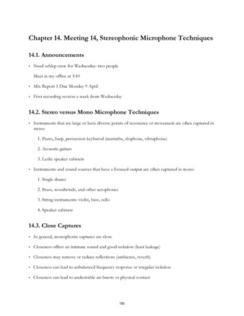
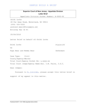
A brief history of microphonesA brief history of microphonesBy Hugh RobjohnsThe humble microphone has been with us forwell over a century and has come a long wayfrom its crude beginnings. Identifying theinventor of the microphone is not a simple task,and depends very much on the definition used.In the beginningThe German physicist Johann Philipp Reis(1834–1874) is a strong candidate for the title.His design for a 'sound transmitter' (optimisedaround 1861), used a metallic strip resting on amembrane with a metal point contactcompleting an electrical circuit. It was Reis'stheory that, as the membrane vibrated, themetal point bounced up and down ‘producingintermittent contact and thus a varying currentsynchronous with the vibrations’. He believed theheight of the bounce and the force of its returncaused variations in the amplitude of the currentpulse proportional to the intensity of the sound. Itworked in a fashion, but not really well enoughfor intelligible speech!the first transmission of intelligible speech overa rudimentary telephone system – the famousrequest by Bell of his assistant: ‘Mr. Watson,come here. I want you’. However, the trueinventor of the telephone was originally disputedsince Bell filed his original patent application forthe telephone on the same day that Gray alsoapplied for a Caveat announcing his intention toclaim the same invention (a caveat being ameans of protecting an idea in advance of a fullpatent application). At this time, though, neitherinventor had actually succeeded in transmittingspeech over a telephone system at all! Thecomplaint was that Bell's first demonstrations ofhis telephone employed a 'liquid transmitter' of akind previously developed and shown publicly byGray – and not of the type documented in Bell'spatent application. However, the courts decidedThe next recorded attempt was that of ElishaGray (1835–1901), an American inventor andone of the founders of what became theWestern Electric Company. The Gray designwas called a 'liquid transmitter' in which adiaphragm was attached to a moveableconductive rod immersed in an acidic solution.A second, fixed rod alongside the firstcontinued the circuit through the solution witha battery connecting the two. Sound pressurevariations through the diaphragm caused theseparation between the two rods to vary inproportion to the sound, producingcorresponding changes in the electricresistance through the cell and, therefore, theamount of current flowing around the circuit.On March 10, 1876 Alexander Graham Bellemployed a very similar transmitter design forBell’s original liquid transmitter microphone1
A brief history of microphonesThe poor quality of these 'liquid transmitters'prompted a number of inventors to pursuealternative avenues of design – David EdwardHughes (1831–1900) was one such man.Already involved in the fledgling telegraphindustry, he was granted a patent in 1855 for atype-printing telegraph instrument, his designbecame very successful in America and waswidely adopted throughout Europe. By 1878 hehad designed a new kind of microphone, usingcarbon granules loosely packed in an enclosedspace. In response to varying pressure from asound diaphragm, the electrical resistancethrough the carbon granules changedproportionally. Although the performance of thiskind of microphone is poor by today's standards(inherently noisy with high distortion), it was asignificant step forwards at the time and wasthe enabling technology for voice telephony.The modern term of 'microphone' also appearsto have been coined by Hughes. Hedemonstrated his transmitter by mounting it ona sound box containing insects whosescratchings were then perceived to be'amplified'. Reports in the newspaperssuggested that the device ‘.acts for the earmuch in the same way that the microscopeserves the eye, hence its name’.Thomas Alva Edison (1847–1931) is well knownfor his work refining the carbon granulemicrophone, resulting in the carbon-buttontransmitter in 1886. This consisted of a cavityfilled with granules of carbonised anthracite coalconfined between two electrodes, one of whichwas attached to a thin iron diaphragm. Edison'stransmitter was simple and cheap tomanufacture, but also very efficient and durable,becoming the basis for the telephonetransmitters used in millions of telephonesaround the world for the majority of the lastcentury.Recording and broadcastingdevelopmentsThe advent of electrical disc recording and radiobroadcasting in the early 1920s stimulated the2development of better quality carbon microphones.Perhaps the best known is an octagonal design oftenseen in photographs of the early broadcastingstations –– the Marconi- Reisz 'transverse-current'carbon microphone. This was invented in Germany bya young employee of the Reisz company, GeorgNeumann (who went on to manufacture microphonesunder his own name). In 1925 the Marconi-Reiszdesign was employed throughout the recently formedBBC, where it remained in daily use for over a decade.However, the inherent instability problems ofcarbon granules provoked the search for betteralternatives. One avenue was the piezoelectric(crystal) transducer, based on fundamentalresearch by the Curies during the previouscentury. These transmitters originally usedquartz or Rochelle salt crystals but the soundquality was not particularly good. Today,piezoelectric foils in contact microphones usespecialised ceramics with very respectableresults.The first capacitor microphone (and associatedimpedance converter/amplifier set) wasdeveloped by EC. Wente in 1917, based onwork at Bell Laboratories in America. This wasa laboratory sound intensity measurement tooland it wasn't until the early 1920s thatprecision stretched-diaphragm condensermicrophones started to be manufactured forrecording and broadcast applications. Thethermionic valve (invented in 1907 by Lee deForest) was a key factor in this, as capacitormicrophones require impedance conversionimpossible to achieve in any other practicalway. Condenser microphones were employed,to a limited extent, in the BBC from 1926 butthey had a reputation for being'temperamental' due to their susceptibility tomoisture causing 'frying noises'!Electromagnetic microphones (moving coil,moving iron and ribbons) were relatively late onthe scene because permanent magnets werevery weak and only electromagnets could createsufficient flux densities. As a consequence, the
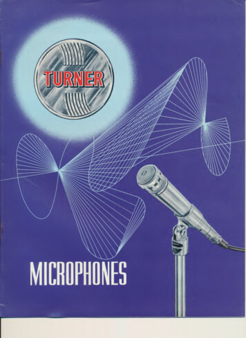
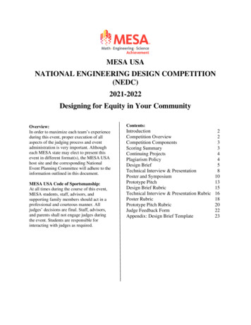
A brief history of microphonesdiaphragm and motive coil, suspended on cottonwool. The magnetic field was created by a largeelectromagnet consuming around 4A from an8V battery!The renowned Alan Blumlein also worked on thedesign of a moving coil microphone tocomplement his electrical record cuttingsystems when he was employed by theColumbiaGraphophone Company (later to become EMI).He used a diaphragm made from a laminate ofbalsa wood (impregnated with celluloid) and thinsheets of aluminium foil. An anodised aluminiummotive coil was riveted to the diaphragm and, inheavy and cumbersome, but were of a qualitydirectly comparable to the condensermicrophones of the time without beingsusceptible to moisture. The BBC/MarconiType A ribbon microphone was introduced in1935 and became the microphone of choicefor the BBC's radio services, although theEMI/ Blumlein HB1B moving coilmicrophone (and its variants, the HB2, HB3and HB4C) were preferred in the televisionservice. This division was partly due to therelative prices of the two microphones: theType A was considered inexpensive at 9,whereas the HB1B cost a whopping 40!It wasn't until powerful permanent magnetsbecame available after the Second World Warthat the external dimensions of ribbon (andmoving coil) microphones could be reduced. Theearliest ribbon microphones employed relativelylong, corrugated diaphragms which were easilystretched and damaged by surprisingly small aircurrents (blowing on the diaphragm woulddestroy it). In 1958 Eugen Beyer changed all thatwith his introduction of the world's first robust,'short diaphragm' ribbon mic. Its capsule shareddimensions similar to the moving coiltransducers of the time and his original designsare still manufactured today.Blumlein’s HB1his first tests, the electromagnet was poweredby batteries borrowed from the cars of severalcolleagues! His first HB1A microphone (namedafter its two main inventors, Blumlein andHolman) was tested in November 1930 andcompared directly with the Western ElectricCondenser Transmitter (CT) microphone, thebest standard of the day. After numerousrevisions, including a screw tensioning systemto adjust the diaphragm resonance, the result(the HB1B) was widely used in the EMIrecording studios and by the new BBCtelevision station at Alexandra Palace when itopened in 1936. The first ribbon microphonealso appeared around 1930 and is believed tohave been developed by Harry Olson, based ona modified ribbon loudspeaker (invented by E.Gerlach in 1924). Early designs wereexcessively large,The first carbon and condenser microphoneswere omnidirectional (pressure operated)devices whilst ribbons introduced pressuregradient operation when the diaphragm wasexposed on both sides, with the resultingfigure-of- eight polar response. However, RCAsoon developed a cardioid pattern ribbon inwhich the upper part of the diaphragm wasopen on both sides (pressure gradient), butthe rear of the lower part was enclosed(pressure operation).An alternative approach, adopted by WesternElectric and ST&C, employed a ribbon capsule(pressure gradient, figure-of-eight response)and a separate moving coil capsule (pressureoperated, omni response) in the same unit.The diaphragms of the two capsules were inclose proximity and their outputs combinedelectrically in series to produce a cardioidpolar response.3
A brief history of microphonesShure, and Electrovoice in America, as well asNeumann, AKG, ST&C and others in Europe.The technique was developed further inGermany with the introduction of a dualdiaphragm condenser capsule. The outputsfrom the resulting pair of back-to-backcardioid capsules were combined electricallyand, by varying the capsule polarisingvoltages, a range of different polar responsescould be obtained.As the film and television industries developed,microphones with greater directionality wererequired to complement long focal-lengthcamera lenses. The first attempts to increasedirectionality relied on crude interferencetechniques with multiple omnidirectionalmicrophones fitted to large planar baffles. Laterrefinements included mounting anomnidirectional microphone at the focus of aparabolic reflector but by the late 1930s,Western Electric and RCA had developed amore practical system. This used a long bundleof narrow-bore tubes mounted in front of, andperpendicular to, the plane of the diaphragm.For on-axis sounds, the tubes played nosignificant role as the soundwaves passedthrough them to arrive coherently at thediaphragm. However, off-axis sounds entereddifferent tubes at varying distances from thediaphragm and, consequently, were largelyincoherent when they arrived, so suffered alarge amount of cancellation.This technique was refined over the yearsresulting in the interference tube (shotgun) micscommonly used today although, unfortunately,directionality at low frequencies remains aproblem unless the interference tube isextremely long. However, digital signalprocessing techniques, combined with a multiplecapsule array, appear to provide one wayforward, and Audio Technica have taken thisapproach with their inventive AT895 directionalmicrophone.One of the problems plaguing early condensermicrophones was their susceptibility to humidity.Essentially the capsule operates at very highimpedance whereas the surrounding air, whendamp, provides a low impedance path throughwhich the polarising charge can escape, causing'frying noises'. In 1924 Riegger came up with theprincipal of the RF condenser microphone as ameans of measuring sound pressure variations downto 0.1Hz. He used a capacitive microphone capsule ina low impedance resonant circuit, excited by a radiofrequency oscillator. Capacitance variations due tosoundwaves caused corresponding changes to theresonant frequency and demodulation of this varyingRF signal provided the required audio frequencyoutput.This laboratory technique was improved by GF.Hull in 1946 and JJ. Zaalberg van Zelst in1947, but it wasn't until the early 1960s thatit was applied to recording microphones. Theimpetus was to replace bulky valve impedanceconverters with much smaller transistorisedcircuits. Bipolar transistors are lowimpedance devices and, although they couldn'tbe employed with conventional condensersystems, they suited the RF condensertechnique very well. Sennheiser pioneered thetechnique for recording microphones andcontinue to manufacturer a wide range of RFcondenser microphones.The miniaturisation of conventional condensermicrophones had to wait until the Field EffectTransistor became available (with its extremelyhigh input gate impedance) to replace valveimpedance converters. Other attempts atminiaturisation have focused on the closeintegration of transducer and amplifying circuitwith many attempts dating back to the 1950s.In one early example, Olson coupled thediaphragm to a pivoted beam-electrode inside athermionic valve, modulating the current flowdirectly according to the displacement of thediaphragm. Later, Sikorski used a diaphragm tovibrate a sapphire pin attached to the emitterregion of a transistor, the induced mechanicalstress affecting its conductivity. Rogers did asimilar thing with a Tunnel Diode in the 1960sand, more recently, purpose designed straingauges have been used. For example, NationalSemiconductor manufacture a piezo-resistivesilicon strain gauge constructed on a flexible4
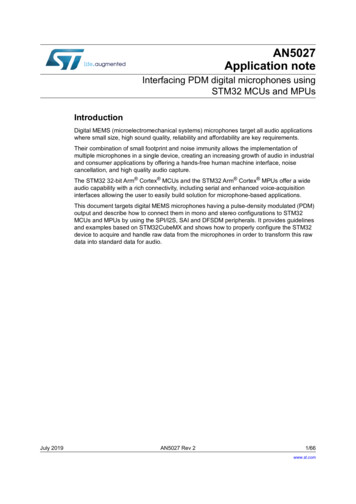
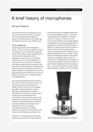
A brief history of microphonesincreasingly challenged by sophisticated prepolarised (back-electret) capsules over the lasttwenty years. The well known B&K (nowDPA)4000 series microphones were amongstthe first electrets to be accepted for qualityrecording applications, and AKG recentlyintroduced their C4000 model – the world'sfirst multi-diaphragm, switched pattern prepolarised microphone.DPA’s 4003AKG’s C4000BInnovationsThe current interest in high sample-rate digitalsystems (96 and 192kHz, and the Sony DSDformat) have encouraged microphonemanufacturers to market microphonesdesigned to take advantage of this new fidelity.Sony's C2 three-capsule microphone has aclaimed bandwidth of 100kHz, and has beenused on some DSD recordings, whilstSennheiser have a reworked version of theirhighly regarded MKH80 RF condensermicrophone – the new MKH800 – which isclaimed to provide a flat response to over50kHz. Many of the Earthworks microphonesalso have a response extending to over40kHz.One of the most important innovations ofmicrophone design was the Soundfield capsule,originally conceived and developed in the 1970sto originate ambisonic surround sound material– a technique developed by Michael Gerzon(Mathematical Institute in Oxford) and ProfessorPB. Fellgett (University of Reading). Theunderlying concepts of ambisonics are relativelysimple (and derive logically from the coincidentstereo investigations of Blumlein forty yearsearlier), although their implementation isextremely complex and highly mathematical.The Soundfield microphone comprises four subcardioid capacitor capsules in a tetrahedralarray, producing 'A-format' signals. These arecombined electronically (with compensation forthe physical separation between capsules) toproduce 'B-format' signals which are the basis of'UHJ Ambisonic' encoded material. These signalsrepresent the outputs of four (perfect) virtualmicrophones consisting of three mutuallyperpendicular figure-of-eight elements – left/right (X), front/back (Y) and up/down (Z), plusan omnidirectional component (W). These canbe thought of as three-dimensional extensionstoBlumlein's original MS configuration. AnAmbisonics decoder calculates whichcombinations of B-format signals to route towhich loudspeakers ('D-format' signals), giveninformation about their number andapproximate location, and how to process themto create incredibly stable and accuratesurround sound images.5
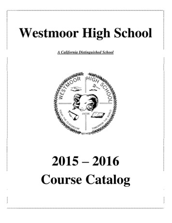
A brief history of microphonessurround sound on location, or in a foley studio, forfeature film production. The decoder is, effectively,preset to produce five loudspeaker outputscorresponding to the locations of a conventional5.1 speaker array – an arrangementSoundfield’s MKVknown as the 'G-format'. Currently, the best of theconventional microphone designs comfortably outstrip analogue preamplifiers in terms of noise anddynamic range, and both have significantly betterperformance than digital converters. TheNeumann’s TLM103Neumann TLM103 condenser microphonehas a self-noise figure of just 7dBA, for example,and a dynamic range of 131dB. However, digitaltechnology and sophisticated conversiontechniques will continue to improve over the nextdecade, and electromechanical transducers willprobably be replaced by opto-mechanical devices.The futureIn recent years, some of the more radicalapproaches to microphone design have includeddetecting the movement, in response to soundpressure variations, of charged particles – asystem analogous to the ionic loudspeaker.Another idea is the laser-velocity transducerwhere a vibrating reflective surface is scannedby a low power laser, the resulting Doppler shiftconveying the audio signal, and over the lastdecade research into 'optical microphones' hasstarted to bear fruit. Laboratory systems havebeen in use for some time but are too unwieldyfor practical recording microphone systems.Sennheiser have developed a compact opticalmicrophone for use in gas pumping stations todetect the sound of leaks without the rick ofexplosion potentially caused by biasing voltagesof traditional microphones. Development iscontinuing in the hope of using the technique intheatrical applications where typical electretcapsuals rapidly suffer damage from the effectsof artist make up and perspiration! However,miniature optical interfaces and related devicesdeveloped for the telecommunicationsindustries, such as miniature laser diodes,polarising beam splitters and photodiodes, arenow enabling the construction of high qualityoptical microphones. At present, usingconventional interferometry techniques and lowpower lasers, the achievable dynamic range istypically a little less than that of a conventionalmicrophone and the distortion is rather worse,but selfnoise is inherently lower. Research inproviding a direct digital output, by opto-sensingthe amount of movement of different parts ofthe diaphragm, is also widespread although theresolution appears extremely limited withpresent technologies.Perhaps a more promising approach is to use'force feedback' in conjunction with an opticalmicrophone. An optical interferometrytechnique detects movement of the diaphragm(of a capacitive capsule) in response to soundpressure variations. A feedback circuit appliesa voltage to the capsule creating anelectrostatic force opposing the movement –the effort required being proportional to thesound6
A brief history of microphonesdepending on the design of the circuitry.Although maximum sound pressure levels inexcess of 135dB can be accommodated andthe frequency response of the system isdictated entirely by the feedback electronics,this technique is, unfortunately, considered tooexpensive to be marketable at present.Hugh Robjohns was a lecturer at the BBC‘sWood Norton training establishments for manyyears. Now a technical author and consultant,he contributes to many technical publicationsand is Technical Editor of Sound on Sound.First published Microphone Data Book 2001 2010 Microphone Data Ltd7
recording and broadcast applications. The thermionic valve (invented in 1907 by Lee de Forest) was a key factor in this, as capacitor microphones require impedance conversion impossible to achieve in any other practical way. Condenser microphones were employed, to a limited extent,