Transcription
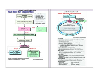
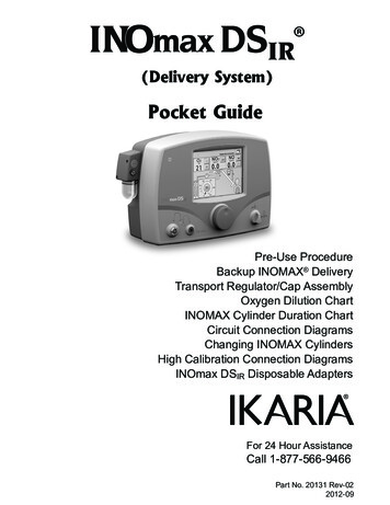
(Delivery System)Pocket GuidePre-Use ProcedureBackup INOMAX DeliveryTransport Regulator/Cap AssemblyOxygen Dilution ChartINOMAX Cylinder Duration ChartCircuit Connection DiagramsChanging INOMAX CylindersHigh Calibration Connection DiagramsINOmax DSIR Disposable AdaptersFor 24 Hour AssistanceCall 1-877-566-9466Part No. 20131 Rev-022012-09
IMPORTANT: This guide is provided as a convenienceand for general information only. Do not usethis product without clearly and thoroughlyunderstanding the most recent revision of theINOmax DSIR Operation Manual. The OperationManual is the source for specific, updatedinformation regarding warnings, cautions,checklists, diagrams, and/or instructionscontained in this guide.OverviewINOmax DSIRThe INOmax DSIR has an interface using infrared (IR) technologywhich will allow the INOmax DSIR to communicate with the INOmeter (which is mounted to each INOMAX cylinder).The INOmax DSIR cart (PN 10018) has a cover with an infraredtransceiver mounted directly above each INOMAX cylinder. WhenINOMAX cylinders are loaded, communication will take place betweenthe INOmax DSIR and the INOmeter after the boot up phase of theINOmax DSIR is complete. A cylinder icon will be displayed on themain screen when an INOMAX cylinder is recognized by theINOmax DSIR.INOmax DSIR Transport Regulator/Cap AssemblyThis assembly is used during medical transport to provide pressurizedINOMAX to the INOmax DSIR as well as communicate INOMAX useinformation via Infrared transceivers between the INOmax DSIR(PN 10007) and the INOmeter.The transport cap assembly provides Infrared technology molded inthe cap. This allows the INOmax DSIR to communicate via Infraredwith the INOmeter, which is mounted to each INOMAX cylinder.Part No. 20131 Rev-022012-092
DefinitionsINOmeter - The factory installed INOmeter is designed for usewith INOMAX cylinders only. This time-metric device records theamount of time the cylinder valve is opened.iButton – Raised silver data port on the side of the INOmeter.SymbolsInfrared Input/Output 2012 Ikaria, Inc.INOMAX , INOmax DSIR , INOblender , INOcal , INOmeter andINOvent are registered trademarks of INO Therapeutics LLC.3Part No. 20131 Rev-022012-09
ContentsPre-Use Checkout.5Backup INOMAX Delivery.12Transport Regulator/Cap Assembly.14Oxygen Dilution Chart.18INOMAX Cylinder 88-size Duration Chart.19INOMAX Cylinder D-size Duration Chart.20Connection to Various Breathing Systems.22A-Plus Medical Babi-Plus Bubble CPAP. 23Bagging Systems While Using the Injector Module.24Bunnell Life Pulse High Frequency Ventilator Circuit.28Connecting INOmax DSIR Sample Tee to the Bunnell LifePulse Circuit.30Connecting INOmax DSIR Injector Module to the Bunnell LifePulse Circuit.30Circle Anesthesia System.31Fisher & Paykel Healthcare Bubble CPAP.32Fisher & Paykel Healthcare Infant Circuit Nasal Cannula.33Fisher & Paykel Healthcare Optiflow Breathing Circuit.34Hamilton Arabella Nasal CPAP.35ICU Ventilator Circuit.36Sensormedics 3100A/B High Frequency Oscillatory Ventilatorwith a Filtered Circuit.37 .Sensormedics 3100A/B High Frequency Oscillatory Ventilatorwith a Rigid or Flexible Circuit.38Spontaneous Breathing Patient on a Mask Circuit.39Spontaneous Breathing Patient on a Nasal Cannula.40Teleflex Medical Comfort Flo Humidification System.41Transport Ventilator Circuit.42Vapotherm 2000i.46Vapotherm Precision Flow.47Viasys Infant Flow CPAP System; Cardinal Airlife nCPAP System. 48Viasys Infant Flow SiPAP.49INOblender Circuit Connection.50Fisher & Paykel Healthcare Neopuff Resuscitator.51Changing INOMAX Cylinders.52High Calibration Connection Diagrams.56INOmax DSIR Disposable Adapters.58Part No. 20131 Rev-022012-094
Pre-Use CheckoutPre-Use Checkout OutlineA.Initial ConnectionsB.High Pressure Leak TestC.Low Range CalibrationD.Purge and Alarm VerificationE.Backup INOMAX Delivery TestF.INOmax DSIR Performance TestG.INOblender Test5Part No. 20131 Rev-022012-09
Pre-Use CheckoutA. Initial Connections1. Check white plastic tip.2. Connect high pressure regulator.Part No. 20131 Rev-022012-096
Pre-Use Checkout3. Connect the INOMAX regulator hose to one of theINOMAX inlets4. Connect the INOblender inlet hose to the INOmax DSIRblender outlet5. Connect the infrared cable to the back of the INOmax DSIR6. Connect the oxygen hose to the INOblender oxygen inlet7. Ensure the water separator cartridge/water trap bottle/sample line and injector module are all in place8. Turn INOmax DSIR ON, verifyspeaker function.374 578677Part No. 20131 Rev-022012-09
Pre-Use CheckoutB. Perform High Pressure Leak Test(Open/Close INOMAXcylinder valve)Wait 30 seconds and ensureno pressure drop.Note: Make sure INOmaxDSIR backup andINOblender are OFF.C. Perform Low Range Calibration(second menu level)Note: Once the calibration is completed (bars turn greenand single tone sounds) press the menu buttontwice to return to the main screen.Part No. 20131 Rev-022012-098
Pre-Use Checkout11021.2.3.4.5.3495876O2 Flowmeter (Connected to wall/tank)O2 Tubing15M x 4.5mm Adapter22M / 15F x 22M / 15F AdapterInjector Module6.7.8.300mm of 22mm HoseGas Sample TeePatient Gas Sample Linewith Nafion9. NO/N2 Injector Tube10. Injector Module Electrical Cable(Assemble connectors and tubing as shown)D. Perform Purge and Alarm Verification1.Ensure cylinder valve is closed.2.Set O2 flowmeter to 10 L/min.3.Purge INOmax DSIR.a. Set INOMAX dose to 40 ppmb. “Cylinder Valve Closed” alarm will occurc. Cylinder gauge pressure should drop to 0 psigd. Purge is complete when “Low NO/N2 Pressure” alarm activates4.Open cylinder valve.5.Turn INOMAX dose to zero (note: The “Set Dose is Zero, CloseCylinder Valve” indicator will appear).9Part No. 20131 Rev-022012-09
Pre-Use CheckoutE. Perform Backup INOMAX Delivery Test1. Turn backup delivery ON.2. V erify “Backup ON”alarm activates.3. Verify values.NO 14-26 ppmNO2 1.0 ppm4. Turn backup delivery OFF.F. Complete INOmax DSIR Performance TestSet DoseAcceptable NOValue40 ppm35-45ppmAcceptable NO2 Value 1.5 ppmFiO2Part No. 20131 Rev-022012-0995% 3%1. Ensure oxygen flow of 10 L/min.2. Set INOMAX dose to 40 ppmand allow values to stabilize.3. Verify values (see table).4. Turn the INOMAX dose to zero.10
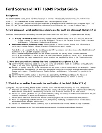
Pre-Use CheckoutG. Perform INOblender TestNote: Ensure INOblender inlet hose is connected to the back ofthe INOmax DSIR and the quick-connect cover is in place.1. Remove the Pre-Use setup oxygen tubing fromthe oxygen flowmeter andconnect it to the front ofthe INOblender.2. Remove the InjectorModule from the Pre-Useset-up and reconnectadapters.240 ppm4353. On the INOblender, setINOMAX dose to 40 ppmand O2 flow to 10 L/min.4. Verify values on theINOmax DSIR.5. Turn the dose and flowto zero and remove thePre-Use set-up from theINOblender.3 10 L/min512Acceptable NO Value32 - 48 ppmThe INOmax DSIR is now ready to connect to the patient. Set the INOMAX dose to be delivered to the patient. Set the appropriate alarm settings on the INOmax DSIR andbreathing device.WARNING: If not starting therapy within 10 minutes,depressurize the INOMAX regulator.End of Pre-Use Checkout11Part No. 20131 Rev-022012-09
Backup INOMAXDeliveryWARNING:When the backup NO delivery mode is used, a flow ofat least 5.0 L/min should be present in the ventilatorcircuit to avoid INOMAX concentrations greater than40 ppm.The backup is intended for short term use when theelectronic delivery system fails until a replacementNO delivery can be brought to the bedside.If the backup is on, along with the main deliverysystem an INOMAX value greater than set will bedelivered (a high priority alarm will be present).The backup mode delivers a variable concentrationof NO to the patient depending on the ventilator flowbeing used. See table below for details.The table below indicates the nominal concentrationsdelivered for different ventilator gas flows.Ventilator/GasFlow MAX cylinder conc. X 0.25 L/min / ventilator flow delivered dosePart No. 20131 Rev-022012-0912
Backup INOMAXDeliveryThe backup delivery provides a fixed flow of 250 mL/min of INOMAXdirectly into the ventilator circuit through the Injector Module.Backup NO delivery is completely pneumatic and is not reliant on theoperation of the main system.Backup delivery mode OFF.Backup delivery mode ON (with a Low Priority alarm).13Part No. 20131 Rev-022012-09
Transport Regulator/Cap AssemblyTransport Regulator/Cap AssemblyWARNING: A new INOMAX cylinder and regulator must be purgedbefore use to ensure the patient does not receive greaterthan 1.0 ppm of NO2. Loss of communication between the INOmax DSIR and theINOMAX cylinder for more than one hour will result ininterruption of INOMAX delivery.Caution: When using the Transport Regulator/Cap Assembly(PN 10022) ensure the cap is in place on the cylinderand the infrared cable is connected to the infraredconnector port on the back of the INOmax DSIR.Note: Check the INOMAX cylinder for the correct product identitylabels, cylinder concentration and expiration date. Ensurethe INOMAX gas cylinder has more than 200 psig.Step OneNote: Ensure the white plastic tip is in place on the regulatorconnector and not chipped or cracked (see Figure 2).Connect a highpressure regulatorto an INOMAXcylinder and tightenthe fitting to theINOMAX cylinder(see Figure 1).Figure 1Part No. 20131 Rev-022012-09Figure 214
Transport Regulator/Cap AssemblyStep TwoConnect the INOMAXregulator hose to one ofthe INOMAX inlets on theback of the INOmax DSIR(see Figure 3).Figure 3Step ThreeConnect the Infrared cable from theTransport Regulator/Cap Assemblyto the back of the INOmax DSIR(see Figure 4).Figure 415Part No. 20131 Rev-022012-09
Transport Regulator/Cap AssemblyStep FourPlace the Cap Assembly over the INOmeter (see Figure 5).Note: Be sure to align the keyway inside the Cap Assembly with theiButton on the INOmeter (see Figure 5 and 6).iButtonThe electricalcord exits thecap directlyabove theiButtonkeywayFigure 5Figure 6Step FiveGrasp the Cap Assembly to open cylinder valve (see Figure 7 and 8).-CLOSEFigure 7Part No. 20131 Rev-022012-09Figure 816 OPEN
Transport Regulator/Cap AssemblyFinal Set-up DiagramThe following diagram and photo illustrates all of the components connected.Additional InformationCommunication will take place between the INOmax DSIR and theINOmeter after the boot up phase of the INOmax DSIR is complete.Note: Cylinder icons are not visible and the dose control buttonwill remain inactive until the INOmax DSIR recognizes anINOMAX cylinder.Note: When using the TransportRegulator/Cap Assemblyonly one cylinder will bedisplayed (see Figure 9).Proceed with theINOmax DSIR Pre-UseCheckout(see page 6)Figure 917Part No. 20131 Rev-022012-09
Oxygen Dilution ChartFor delivery with 800 ppm cylinder ofINOMAX (nitric oxide) for inhalation.(Illustrative Only)Set FiO2INOMAX .540.720.90Actual FiO2Caution FiO2 less than 21%Please Note:The calculations on this chart have been determined based on an800 ppm cylinder of INOMAX (nitric oxide) for inhalation.This chart is representative of a range of doses available on theINOmax DSIR and doses higher than 20 ppm are not intended as therecommended therapeutic dose.Calculations are considered estimates and may vary under clinicalconditions.All numbers have been rounded to the nearest hundredth.Part No. 20131 Rev-022012-0918
Duration Chart(88-size)INOMAX Cylinder 88-SizeFor an 88-Size 800 ppm Cylinder Concentration*(Illustrative Only)INOMAX oursThis chart is representative of a range of doses availableon the INOmax DSIR and doses higher than 20 ppm are notintended as the recommended therapeutic dose.* All calculations for the table above are based on a full cylinder of 2000 psig,1963 liters “88” cylinder, and also accounting for cylinder change at 200 psig. Thefigures are calculated on total continuous flow cylinder conversion factor 0.98. INOMAX flow [Desired dose X total ventilator flow] /[Cylinder concentration - desired dose] Cylinder volume Cylinder conversion factor X cylinder pressure psig Cylinder duration Cylinder volume / INOMAX flow rateCalculations are considered estimates and may vary under clinicalcircumstances. For more information, call 1-877-KNOW-INO (1-877-566-9466).19Part No. 20131 Rev-022012-09
Duration Chart(D-size)INOMAX Cylinder D-SizeFor a D-Size 800 ppm Cylinder Concentration*(Illustrative Only)INOMAX y used in transportThis chart is representative of a range of doses availableon the INOmax DSIR and doses higher than 20 ppm are notintended as the recommended therapeutic dose.* All calculations for the table above are based on a full cylinder of 2000 psig,353 liter “D” cylinder, and also accounting for cylinder change at 200 psig. Thefigures are calculated on total continuous flow cylinder conversion factor 0.18. INOMAX flow [Desired dose X total ventilator flow] /[Cylinder concentration - desired dose] Cylinder volume Cylinder conversion factor X cylinder pressure psig Cylinder duration Cylinder volume / INOMAX flow rateCalculations are considered estimates and may vary under clinicalcircumstances. For more information, call 1-877-KNOW-INO (1-877-566-9466).Part No. 20131 Rev-022012-0920
Duration Chart(D-size)(Intentionally left blank)21Part No. 20131 Rev-022012-09
Circuit ConnectionDiagramsProper use of these products depends on careful reading andunderstanding of labeling and instructions. Please refer to theINOmax DSIR and INOblender operation manuals for guidance. Alsorefer to the specific breathing device operation manual or instructionsfor use.INOmax DSIR Warnings: INOmax DSIR subtracts gas from the breathing circuit via thegas sampling system at 230 mL per minute; this can affect thesensitivity of a flow triggered synchronized breath mode ofsome ventilators. The trigger sensitivity of the ventilator shouldbe checked after connecting the INOmax DSIR to the breathingcircuit. Patient disconnect and high-pressure alarms are required forthe ventilator.INOmax DSIR Cautions: Insert the Injector Module on the dry side of the breathing circuit priorto the humidifier (this will ensure correct flow measurement). Avoid medications interfering with the gas monitoring system;administer any aerosolized medications distal to the sampling tee.Part No. 20131 Rev-022012-0922
Circuit ConnectionDiagramsConnection to the A-Plus Medical Babi-PlusBubble CPAP151142121.2.3.4.5.6.7.8.5341311Oxygen SourceOxygen TubingPressure Relief ManifoldInjector ModuleTemperature Probe90 Degree Sample Port AdapterNasal ProngsBabi Plus Bubble PAP Valve1099.10.11.12.13.14.15.23687Tee AdapterBreathing CircuitHumidifierNO/N2 Injector TubeInjector Module Electrical CableINOmax DSIRPatient Gas Sample Line with NafionPart No. 20131 Rev-022012-09
Circuit ConnectionDiagramsConnection to Bagging Systems While Usingthe Injector ModuleWARNING: To minimize the delivered concentration of NO2,the following steps should be taken for use withthe manual resuscitator bags: Use the smallest bag adequate to deliver thedesired tidal volume. Inspiratory tubing lengths greater than 72inches should not be used. Use the highest fresh gas flow rated (up to 15L/min) that is practical. Use the lowest practical inspired oxygenconcentration. After starting fresh gas flow, squeeze the bagseveral times to empty residual gas in thebag prior to using the system to ventilate apatient.Part No. 20131 Rev-022012-0924
Circuit 1.12.34576O2 Flowmeter (wall outlet or cylinder)O2 Tubing15M X 4.5mm Adapter22M/15F X 22M/15F AdapterInjector Module15M X 4.5mm AdapterO2 TubingO2 Tubing Sample TeePatient Gas Sample Line with NafionNO/N2 Injector TubeResuscitator Bag with O2 ReservoirInjector Module Electrical Cable25Part No. 20131 Rev-022012-09
Circuit ConnectionDiagramsWARNING: The hyperinflation bag will, under some conditions, contain NO2 in excess of1 ppm. Use of large tidal volume breaths may expose the patients to the NO2present in the bag, for part of the breath. In general, if the inspiratory flow rateinduced by the manual ventilation does not exceed the fresh gas flow rate,the patient should not be exposed to the concentrations of NO2 present in thehyperinflation bag. Adult and infant hyperinflation bags generate more NO2 when used at lowerminute ventilation. If use of the bag is interrupted (for example to adjust thetracheal tube), before resuming ventilation of the patient, the user shouldsqueeze the bag several times to empty residual gas from the bag. Because of the potential for inhalation of excessive concentrations ofNO2, and the difficulty in monitoring the peak inhaled NO2 concentrations,ventilation with a hyperinflation bag or self inflating bag is intended only forshort term use. The monitoring system within the INOmax DSIR will not detect generation ofNO2 within the hyperinflation bag or self-inflating bag devices and the alarmsfor excessive NO2 cannot warn of NO2 produced within the manual bagsystem. To minimize the delivered concentration of NO2, the following steps should betaken for use with the manual resuscitator bags:- Concentrations greater than 20 ppm NO should not be used because ofexcessive NO2 generation.- Use the smallest bag adequate to deliver the desired tidal volume.- Inspiratory tubing lengths greater than 72 inches should not be used.- Use the highest fresh gas flow rate (up to 15 L/min) that is practical.- Use the lowest practical inspired oxygen concentration.- After starting fresh gas flow, squeeze the bag several times to emptyresidual gas in the bag prior to using the system to ventilate a patient.Part No. 20131 Rev-022012-0926
Circuit ConnectionDiagramsConnection to Bagging Systems While Usingthe Injector Module342561713 12 111.2.3.4.5.6.7.1098O2 FlowmeterInjector Module Electrical CableNO/N2 Injector TubePatient Gas Sample Line with NafionO2 TubingO2 Tubing Sample TeeHyper-Inflation Bag8.9.10.11.12.13.27Pressure Gauge15M X 4.5mm AdapterInjector Module22M/15F X 22M/15F Adapter15M X 4.5mm AdapterO2 TubingPart No. 20131 Rev-022012-09
Circuit ConnectionDiagramsConnection to a Bunnell Life PulseHigh Frequency Ventilator CircuitWARNING: The INOmax DSIR backup mode (250 mL/min.) should notbe used with the Bunnell Life Pulse as ventilator flow ratesare normally below the recommended ventilator flows. Place the Life Pulse in Standby prior to suctioning thepatient to avoid NO delivery transiently exceeding theset dose by up to 30 ppm. Press ENTER to reestablishventilation as soon as the catheter is removed from theairway. This will limit the extent of over delivery above theNO set dose.Caution: If the set dose is below 5 ppm and the Servo pressure is 2.0 psig.or less, this will result in flow rates outside of the specification ofthe Injector Module and fluctuating NO values may result. A one-way valve should be placed between the injector moduleand the humidifier chamber to prevent water from backing up intothe injector module if the Life Pulse is either put into Standby orcycled OFF. There are higher pressures in the breathing circuit than normal;use only parts provided in disposable package #50046 and tightlysecure all connections.Part No. 20131 Rev-022012-0928
Circuit ConnectionDiagramsConnection to a Bunnell Life PulseHigh Frequency Ventilator Circuit (cont.)12435610 91.2.3.4.5.INOmax DSIRBunnell Life PulseHumidifierHumidifierConventional Ventilator6.7.8.9.10.87Life Port AdapterEndotracheal TubeSample TeePatient BoxInjector Module29Part No. 20131 Rev-022012-09
Circuit ConnectionDiagramsConnecting INOmax DSIR Sample Tee to theBunnell Life Pulse Circuit1.2.123From Patient BoxCut Green tube at midpoint(approximately 6 in. from the Life Port Adapter)43.4.Insert Sample TeeLife Port AdapterConnecting INOmax DSIR Injector Module to theBunnell Life Pulse Circuit11.2.3.4.2354Gas Out Tube from Vent15M X 4.5mm I.D. Adapter22M/15F X 22M/15F AdapterInjector Module5.6.7.8.67815M X 4.5mm I.D. Adapter3cm Piece of Green Gas Out TubeOne-Way ValveGreen Gas Out Tube to HumidifierWARNING: The INOmax DSIR backup mode (250 mL/min.) should not beused with the Bunnell Life Pulse as ventilator flow rates arenormally below the recommended ventilator flows. Place the Life Pulse in Standby prior to suctioning the patient toavoid NO delivery transiently exceeding the set dose by up to30 ppm. Press ENTER to reestablish ventilation as soon as thecatheter is removed from the airway. This will limit the extent ofover delivery above the NO set dose.Part No. 20131 Rev-022012-0930
Circuit ConnectionDiagramsConnection to a Circle Anesthesia System1141.2.3.4.5.6.7.13121110b210Patient Gas Sample Line withNafionPatient Gas Sample LineInput ConnectionINOmax DSIRBellows AssemblyVentilatorVentilator Drive GasAbsorber Expiratory Port10a5439 8768. Absorber Inspiratory Port9. Absorber10. Injector Modulea. Injector Module Input Endb. Injector Module Output End11. Inspiratory Tubing12. 22M/15F X 22M/15F Adapter13. Gas Sample Tee14. Patient WyeWARNING: Fresh gas flow should be equal to or greaterthan patient minute ventilation to avoidrecirculation of gases.31Part No. 20131 Rev-022012-09
Circuit ConnectionDiagramsConnection to the Fisher & Paykel Bubble CPAP1611523144131.2.3.4.5.6.7.8.9.41211Oxygen SourceOxygen TubingBubble CPAP Pressure Manifold22F X 15M Adapter22M/15F X 22M/15F AdapterInjector ModuleTemperature ProbeNasal Prong Infant InterfaceBubble CPAP GeneratorPart No. 20131 Rev-022012-09875610910. F/P Inline Infant Nebulizer Kit(RT010) Adapter11. Breathing Circuit12. Humidifier13. NO/N2 Injector Tube14. Injector Module Electrical Cable15. INOmax DSIR16. Patient Gas Sample Line with Nafion32
Circuit ConnectionDiagramsConnection to the Fisher & Paykel Infant CircuitNasal Cannula123475689105151.2.3.4.5.6.7.8.14 13129.10.11.12.13.14.15.Patient Gas Sample Line with NafionINOmax DSIROxygen SourceOxygen Tubing22F X 15M AdapterInjector ModulePressure Relief Manifold22M/15F X 22M/15F Adapter3311Injector Module Electrical CableNO/N2 Injector TubeHumidifierBreathing CircuitTemperature ProbeGas Sample TeeNasal CannulaPart No. 20131 Rev-022012-09
Circuit ConnectionDiagramsConnection to the Fisher & Paykel OptiflowBreathing Circuit12317647516151.2.3.4.5.6.7.8.9.814 13 12 11Patient Gas Sample Line with NafionINOmax DSIROxygen SourceBreathing Circuit HoseInjector ModuleInjector Module Electrical CableNO/N2 Injector Tube22F X 15M AdapterHumidifierPart No. 20131 g CircuitTemperature ProbeGas Sample Tee22M/15F X 22M/15F Adapter22 mm ID X 22 mm ID Cuff AdapterOptiflow TracheostomyOptiflow Nasal CannulaOptiflow Mask
Circuit ConnectionDiagramsConnection to the Hamilton Arabella Nasal ent Gas Sample Line with NafionINOmax DSIRNO/N2 Injector TubeInjector Module Electrical CableInjector Module3565422F X 15M AdapterHumidifierHeated Delivery CircuitUniversal Generator90 Degree Sample Port AdapterPart No. 20131 Rev-022012-09
Circuit ConnectionDiagramsICU Ventilator 15.141311 10 912Patient WyeVentilatoraVentilator Expiratory PortVentilator Inspiratory PortPatient Gas Sample Line Input ConnectionbINOmax DSIRNO/N2 Injector Tube Front Panel ConnectionInjector Module Electrical Cable FrontPanel ConnectionInjector Module Electrical Cable ConnectionInjector Module NO/N2 Injector Tube ConnectionHumidifier InletHumidifierHumidifier OutletPatient Gas Sample Line with NafionGas Sample TeePart No. 20131 Rev-022012-0936ca. Injector Moduleb. 22F Inletc. 22M / 15F Outlet
Circuit ConnectionDiagramsSensormedics 3100A/B High FrequencyOscillatory Ventilator with a Filtered Circuit134 526789181711101112acb16 15 141.2.3.4.5.6.7.8.9.a. Injector Moduleb. 22F Inletc. 22M / 15F Outlet13Sensormedics 3100A/B VentilatorVentilator Outlet22M AdapterInjector ModuleInjector Module ElectricalCable ConnectionINOmax DSIRNO/N2 Injector Tube15M AdapterOne-Way Valve10.11.12.13.14.15.16.17.18.Paw Limit Valve ControlFilterHumidifier InletHumidifier OutletBias Flow TubePatient Gas Sample Line with Nafion90 Degree Sample Port AdapterDump Valve ControlPaw Control ValveWARNING: Omission of the one-way valve may result inhigh NO delivery.37Part No. 20131 Rev-022012-09
Circuit ConnectionDiagramsSensormedics 3100A/B High Frequency OscillatoryVentilator with a Rigid or Flexible Circuit13 42567813910121.2.3.4.5.6.7.8.acba. Injector Moduleb. 22F Inletc. 22M / 15F Outlet11Sensormedics 3100A/B VentilatorVentilator Outlet22M AdapterInjector ModuleINOmax DSIRNO/N2 Injector Tube ConnectionInjector Module Electrical Cable ConnectionOne-Way Valve9. Humidifier Inlet10. Humidifier Outlet11. Patient Gas SampleLine with Nafion12. 90 Degree SamplePort Adapter13. Bias Flow TubeWARNING: Omission of the one-way valve may resultin high NO delivery.Part No. 20131 Rev-022012-0938
Circuit ConnectionDiagramsConnection to Spontaneous Breathing Patienton a Mask Circuit1516141311.2.3.4.5.6.7.8.23 45O2 Tubing15M X 4.5mm Adapter22M/15F X 22M/15F AdapterBreathing Circuit TeeBreathing Circuit BagInjector ModuleBreathing Circuit HoseGas Sample Tee69.10.11.12.13.14.15.16.78910111222M/15F X 22M/15F AdapterOne-Way ValveSealed Face MaskOne-Way ValvePatient Gas Sample Line with NafionNO/N2 Injector TubeInjector Module Electrical CableO2 Flowmeter (wall outlet or cylinder)39Part No. 20131 Rev-022012-09
Circuit ConnectionDiagramsConnection to Spontaneous Breathing Patienton a Nasal CannulaThe INOmax DSIR can be used with nasal cannula to deliverINOMAX concentrations from 5-80 ppm and an oxygen flowrate as low as 2 L/min.WARNING: Do not use the INOmax DSIR backup mode withflow rates less than 5 L/min.91101121.2.3.4.5.6.3 454 6O2 FlowmeterO2 Tubing15M x 4.5mm Adapter22M/15F x 22M/15F Adapter300mm of 22mm HoseInjector ModulePart No. 20131 Rev-022012-0957.8.9.10.11.404 378O2 Tubing Sample TeePatient Nasal CannulaPatient Gas Sample Line with NafionNO/N2 Injector TubeInjector Module Electrical Cable
Circuit ConnectionDiagramsConnection to the Teleflex Medical Comfort FloHumidification System1213345614781516121.2.3.4.1711 10Patient GasSample Line withNafionINOmax DSIRInjector ModuleSystem PressureRelief Valve95.6.7.8.9.Air/Oxygen Blender orOxygen BlenderOxygen TubingTemperature Probe(Short Cable)Angled 22 mm ConnectorPatient Circuit4110. TemperatureProbe Connector11. SecondTemperatureProbe Connector12. Comfort FloCannula13. Injector ModuleElectrical Cable14. NO/N2 InjectorTube15. ConchaThermHeated Humidifier16. 90 DegreeSample PortAdapter17. TemperatureProbe (LongCable)Part No. 20131 Rev-022012-09
Circuit ConnectionDiagramsTransport Ventilator Diagram6543217811131.2.3.4.5.6.91210Patient WyeExpiratory Breathing Circuit HosePatient Gas Sample Line withNafionVentilator Expiratory ValveVentilatorINOmax DSIRPart No. 20131 Rev-022012-09427.8.9.10.11.12.13.Ventilator Inspiratory Port22M/15F X 22M/15F AdapterInjector Module Electrical CableNO/N2 Injector TubeInjector ModuleInspiratory Breathing Circuit HoseGas Sample Tee
Circuit ConnectionDiagramsWARNING: If the INOmax DSIR is to be used in a transportvehicle, it should be affixed to the transportmounting post part number 10009 (see Figure 10).Figure 10Figure 11Caution:When using the Transport Regulator/Cap Assembly (PN 10022)ensure the cap is fully seated and in place on the INOmeterand the infrared cable is connected and latched to the infraredconnector port on the back of the INOmax DSIR (see Figure 11).It is recommended that a second transport regulator capassembly is available during all transports.43Part No. 20131 Rev-022012-09
Circuit ConnectionDiagramsSingle-Li
1. Remove the Pre-Use set-up oxygen tubing from the oxygen flowmeter and connect it to the front of the INOblender. 2. Remove the Injector Module from the Pre-Use set-up and reconnect adapters. 3. On the INOblender, set INOMAX dose to 40 ppm and O 2 flow to 10 L/min. 4. Verify values on th