Transcription
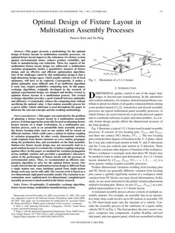
IEEE TRANSACTIONS ON AUTOMATION SCIENCE AND ENGINEERING, VOL. 1, NO. 2, OCTOBER 2004133Optimal Design of Fixture Layout inMultistation Assembly ProcessesPansoo Kim and Yu DingAbstract—This paper presents a methodology for the optimaldesign of fixture layouts in multistation assembly processes. Anoptimal fixture layout improves the robustness of a fixture systemagainst environmental noises, reduces product variability, andleads to manufacturing cost reduction. Three key aspects of themultistation fixture layout design are addressed: a multistationvariation propagation model, a quantitative measure of fixturedesign, and an effective and efficient optimization algorithm.One of the challenges raised by this multistation design is that ahigh-dimension design space, which usually embeds a lot of localoptimums, will have to be explored. Consequently, it makes aglobal optimality more difficult and, if an inefficient algorithmis used, may require prohibitive computing time. In this paper,exchange algorithms, originally developed in the research ofoptimal experimental design, are adopted and further revised tooptimize fixture layouts in a multistation process. The revisedexchange algorithm provides a good tradeoff between optimalityand efficiency: it remarkably reduces the computing time withoutsacrificing the optimal value. A four-station assembly process fora sports utility vehicle sideframe is used throughout the paper toillustrate the relevant concepts and the resulting methodology.Note to practitioners—This paper was motivated by the problemof planning a fixture locator layout in a multistation assemblyprocess. Existing approaches generally focused on planning fixturelocator layouts on a single workstation. In a multistation production process, such as an automobile body assembly process,the fixture locating holes used on one station will be reused ondifferent stations, which could cause a station-to-station couplingin variation propagation. In other words, dimensional variationcould originate from fixture elements on every station, propagatealong the production line, and accumulate on the final assembly.Station-wise fixture layout design may not necessarily lead to agood solution because it overlooks the variation coupling and propagation effect. In this paper, we modeled the variation propagationacross multiple stations and provided a quantitative characterization of the performance of fixture layout with the presence ofenvironmental noises. Then, we recommended an efficient computation algorithm to solve for the optimal fixture layout. Ourresults showed that the multistation layout design is different froma single station one; some intuitions gained from single-stationdesign work may not be still valid. The current work is based on atwo-dimensional, rigid panel assembly model. The extension to accommodate more sophisticated two-dimensional, complaint-partassembly processes is much needed in the future research.Index Terms—D-optimality, E-optimality, exchange algorithm,fixture layout design, multistation manufacturing system.Manuscript received November 26, 2002; revised June 27, 2003. This workwas supported in part by the National Science Foundation under Grant DMI0217481. This paper was recommended for publication by Associate EditorM. Wang and Editor I. Walker upon evaluation of the reviewers’ comments.P. Kim is with Samsung Electronics, Chungnam, 336-841, South Korea(e-mail: pan.kim@samsung.com).Y. Ding is with the Industrial Engineering Department, Texas A&M University, College Station, TX 77843 USA (e-mail: yuding@iemail.tamu.edu).Digital Object Identifier 10.1109/TASE.2004.835570Fig. 1.Illustration of a 3-2-1 fixture.I. INTRODUCTIONDIMENSIONAL quality control is one of the major challenges in discrete-part manufacturing. In the automotiveand aviation industries, for instance, dimensional problems contribute to about two-thirds of all quality-related problems duringa new product launch [1], [2]. Automotive and aircraft assemblyprocesses are typical multistation panel assembly processes, inwhich fixtures are used extensively to provide physical supportand to coordinate reference to parts and subassemblies. As a result, fixture design greatly affects the dimensional accuracy ofthe final products.Fig. 1 illustrates a typical 3-2-1 fixture used in panel assemblyand,processes. It consists of two locating pins,. The two locatingand three net contact (NC) blocks,pins constrain three degrees of freedom in the - plane, wherethe 4-way pin controls part motion in both - and -directionsand the 2-way pin controls part motion in -direction. ThreeNC blocks constrain other degrees of freedom of the workpiece.When a workpiece is nonrigid, more than three NC blocks maybe needed in order to reduce part deformation. An -2-1 fixturelayout, denoted by, is amore generic setting in panel assembly processes.Product dimensional variations resulting from locating pinsand NC blocks are generally different: variation from locatingpins causes a (global) rigid-body motion of a workpiece whilevariation from NC blocks can cause (local) deformations. In thisstudy, we are more interested in the global variation phenomenaas a simrelated to locating pins. Hence, we useplified representation of an -2-1 fixture layout.A real panel assembly process always consists of multiple assembly stations. For example, an assembly line in an automotive body-shop could involve up to 80 stations to assemble 150to 250 sheet-metal parts into the structure of a vehicle. Consider the assembly process of the sideframe of a sports utilityvehicle (SUV) in Fig. 2. The final product, the inner-panel complete, comprises four components: A-pillar, B-pillar, rail-roofside panel, and rear quarter panel, which are assembled on three1545-5955/04 20.00 2004 IEEE
134IEEE TRANSACTIONS ON AUTOMATION SCIENCE AND ENGINEERING, VOL. 1, NO. 2, OCTOBER 2004Following this introduction, Section II reviews the researchrelevant to fixture design. In Section III, we briefly discuss thevariation propagation model and explain major variation phenomena in a panel assembly process. Section IV discusses theselection of design measures. The optimization algorithms, illustrated by solving the fixture-layout in the SUV sideframe assembly process, are presented in Section V. Finally, we concludethis paper in Section VI.II. RELATED WORKFig. 2. Assembly process of an SUV sideframe. (a) Station I, (b) Station II,(c) Station III, and (d) Station IV: Key product features.stations (Stations I, II, and III). Then, the final assembly is inspected at Station IV [ –marked in Fig. 2(d) are key dimensional features].In such a multistation process, the aforementioned 3-2-1 fixture is used on every station to ensure product dimensional accuracy. In Fig. 2, – are the so-called principal locating points(PLP), which are the pinholes used to position a part on an assembly station. However, the same symbols are also used interchangeably to represent locating pins. Thus, a fixture layout ina multistation process can be represented using these PLPs asfollows:where the assembly process starts from Station I (indicatedby the subscript) and the arrow represents a transition fromone station to the next. As an example,means that at Station II the first workpiece, the subassemblyandand the second“A-pillar B-pillar,” is located byand .workpiece, the rail roof side panel, is located byIn a multistation assembly process, dimensional variationcould originate from fixture elements on every station, propagate along the production line, and accumulate on the finalassembly. The dimensional quality of the final assembly depends on: 1) input variation level and 2) process sensitivityto variation inputs. The former issue is usually addressed bytolerance design. This paper focuses on the second issue, i.e.,an optimal design of fixture layouts in a multistation assemblyprocess so that the process is insensitive to variation input.Fixture layout design in a multistation process determines thelocations of fixtures on every assembly station. The problem isequivalent to the determination of PLP locations on an assemblyproduct. Three aspects that should be addressed are:1) a variation propagation model that links fixture variationinputs on every station to product dimensional variation;2) a quantitative design measure that benchmarks the sensitivity of different fixture layouts;3) optimization algorithms that find the optimal fixturelayout.Earlier research on fixture design employed kinematical andmechanical analysis to explore accessibility, detachability, andlocation uniqueness of a fixture, aiming at the automatic generation of fixture layouts [3]. Heuristic algorithms were developed for automatic generation of fixture configurations [4], [5].Trappery and Liu [6] summarized the research before 1990 onfixture-design automation and a more recent summary can befound in [7, Sec.1].These fixture designs are considered deterministic approaches because they consider neither random manufacturingerrors of fixture elements nor workpiece positioning errorsinduced by fixturing operations. Since a workpiece or a fixture element is unavoidably subject to manufacturing error,researchers studied the problem of robust fixture design in astochastic environment [7]–[21].One branch of robust fixture design aims at finding optimalfixture positions that minimize the deflection of a compliantworkpiece under working load [8]–[14]. This research usuallydoes not consider manufacturing errors of fixture elements.However, fixture-related local deformation and micro-slippageare considered error sources [10], [11].Another branch of robust fixture design is known as the variational approach because it considers fixture error or workpiecesurface error and tries to find an optimal fixture layout thatmakes the positioning accuracy of a workpiece insensitive toinput errors [7], [15]–[17]. Variational fixture design often startswith developing a sensitivity measure that characterizes the robustness of a fixture system. This sensitivity measure is determined by fixture layout and is independent of fixture error input.The smaller the sensitivity, the more robust the fixture system.For example, Wang [15] maximized the determinant of the information matrix (D-optimality), which is the inverse of the sensitivity matrix, and Cai et al. [7] minimized the Euclidean normof their sensitivity matrix. Meanwhile, heuristic or rule-basedmethods have also been developed for designing robust fixturelayout [17]. Research work in [18]–[21] is also relevant in thesense that it provides variation/tolerance analysis of a fixturesystem while the difference is that the issue of fixture synthesisis not addressed.Past variational fixture designs were conducted mainly at thesingle-machine level rather than at the multistation system level,i.e., the fixture layout being optimized is limited to a singleworkstation. Based on our description of the 3-2-1 fixture usedin panel assembly processes, it is apparent that a station-wiseoptimization of fixture layout is different from a system-wideoptimization. Suppose that one had optimized the positions
KIM AND DING: OPTIMAL DESIGN OF FIXTURE LAYOUT IN MULTISTATION ASSEMBLY PROCESSES135TABLE ICOMPARISON OF FIXTURE-DESIGN METHODOLOGIESFig. 3. Fixture-related variation sources.of, andon Station I. Note thatand(thePLPs on A-pillar and B-pillar, respectively) will be reused onStation II. Thus, when a station-wise optimization is carriedout on Station II, one could choose to optimize all fixtures onStation II as ifandwere not optimized on Station I orandand onlyhe/she can keep the optimized positions ofoptimize the fixture layout ( and ) that supports the newlyadded part. Obviously, neither approach will lead to an overalloptimal fixture-layout in a multistation process.Research on multistation fixture optimization is very limitedbecause of the inherent difficulty resulting from multistationvariation modeling, development of design criteria, as well aschoice of efficient optimization methods. Recent research workaddresses the issue of multistation variation modeling using either a station-indexed state–space model [22]–[25] or a datummachining surface relationship graph (DMG) [26]. Xiong et al.[27], [28] further studied nonlinear fixturing models for variation prediction in multistation aluminum welded assemblies.Based on linear variation models developed for panel assemblyprocesses [22]–[24], this paper will continue the developmentof design criteria and optimization algorithms for multistationfixture design.One more note is on fixture diagnosis [29]–[32], which is topinpoint malfunctioning fixtures based on in-line measurementsfrom Optical CMMs. It is apparent that fixture diagnosis is anin-line technique that complements the off-line fixture designmethod. It is not surprising, though, that both types of researchshare the common theoretical background of variation modelingand analysis. Overall, the methodologies reviewed in this section are summarized in Table I.III. STATE–SPACE VARIATION MODELDimensional variation models that link fixture variation todimensional measurements are developed using standard kinematics analysis [33]. A few variation propagation models wererecently developed for multistation assembly processes using astate-space representation [22]–[24]. Since this model is an integral part of multistation fixture design, we briefly explain keyelements in the modeling procedure and then present a generalmodel structure. A two-dimensional (2-D) assembly process ismodeled in this paper.There are two major fixture-related variation sources, as illustrated in Fig. 3. One is the variation contributed by fixture locators on station [Fig. 3(a)] and another is the variation inducedwhen a subassembly is transferred to the next station wherea different fixture layout is used to position the subassembly[Fig. 3(b)].The modeling procedure starts with an individual station .Denote the product dimensional state of part on stationas, which are the deviationsassociated with its three degrees of freedom, where is theis the orientation angle. Supperturbation operator andpose that this part is located by the th fixture pairon station , whose random deviations are denoted as. Apparently,can be relatedthrough a linearizationto(1)
136Fig. 4.IEEE TRANSACTIONS ON AUTOMATION SCIENCE AND ENGINEERING, VOL. 1, NO. 2, OCTOBER 2004Diagram of a multistation manufacturing process.whereandare the nominal coordinates of locaand , respectively, andincludes the unmodeledtorshigher order terms.Generally, the state of the product, which comprises parts,is represented by. If part has notyet appeared on station , the corresponding. Thefixture deviation vector on station is,whereis the number of fixture pairs on station . Productmeasurements at station are included in . For the examplein Fig. 3(a),,which are the deviations associated with product featuresand.The basic idea of a state–space variation model is to considera multistation process as a sequential system but replace the timeindex in a traditional state–space model with a station index. Forthe process in Fig. 4, the station-indexed state–space model canbe expressed asand(2)where is the number of stations andrepresents measurement noises. In this variation model,models the effect offixture variationon the product dimensional state. Itaggregates transformation matrices, each of which is similar tothe one in (1), for modeling allfixture pairs. Matrixincludes the information of key product features (the number andlocations of those features on station ). In the process describedin Fig. 2,andbecause key product featuresare measured only on Station IV after assembly operations onStations I, II, III.One difference between a multistation variation model anda single-station model is the existence of matrixthat linksproduct statesacross different stations. Matrix dependson fixture layouts on two adjacent stations. The procedure todetermine is conceptually similar to that of determining orbut algebraically complicated (for more details, please referto [22], [23], or [24]). If there is no change in fixture layoutsacross stations, simply becomes an identity matrix (e.g., theprocess described in [34]), and then the multistation model in (2)becomes a simple summation of multiple single-station models.However, in the multistation panel assembly process described in Section I, a change in fixture layouts occurs when thesubassembly proceeds to a new station. Fig. 3(b) illustrates theeffect due to the change in fixture layouts; it results in a reorientation of the subassembly. If there were fixture deviations inprevious stations, the reorientation-induced error could happento a part even if fixtures at the current station are free of error[e.g., part 1 in Fig. 3(b)].This reorientation is almost unavoidable for a multistationpanel assembly process because a subset of PLPs is necessaryAFig. 5. Singularity ofdue to reorientation. (a) Observed assembly.(b) Fixture-pair one: normal and fixture-pair two: faulty. (c) Fixture-pair one:faulty and fixture-pair two: normal. (d) Fixture-pair one: faulty and fixture-pairtwo: faulty.to reposition a subassembly on a downstream station. Due tothis reorientation effect, in the multistation variation modeltakes a structure other than an identity matrix. More importantly,and maybe surprisingly,is singular throughout the process.This singularity issue was identified for a multistation assemblyprocess in [31].We present an intuitive explanation for whyis singularwhen fixture layouts change across stations. Consider the simpleexample in Fig. 5, where several possible fixture errors on anupstream station could have caused the same resulting patternof part deviation.When this resulting deviation pattern is observed on Station[Fig. 5(a)], the faulty fixture pair on Station causingthe deviation pattern could be either fixture-pair one [Fig. 5(c)],fixture-pair two [Fig. 5(b)], or both fixture pairs [Fig. 5(d)]. Assembly deviation at one station is related to its deviation incurred at the previous station through matrix , i.e.,, by neglecting other terms. Noticing that, given,there is no unique solution forbecause of the above-mentioned ambiguity, we can conclude thatis singular. The singularity of matrix is a general problem existing in panel assembly processes and will affect our choice of design criterionduring later development.Following the modeling procedure in [22] and [23], we developed a state-space variation model for the four-station assemblyprocess of the SUV sideframe in Fig. 2. In this model, the fixtureused on Station IV is considered well maintained and calibratedwith much higher repeatability than those on a regular assemblystation. Thus, fixture locators on the measurement station are assumed free of error, i.e.,, while deviation inputs fromfixtures on three assembly stations,, and , are included.Thus, the state–space model is(3)whererepresents product error resulting from the part-fabrication process (which is a stamping process for panel assembly)prior to the assembly process. Due to limited space, numerical
KIM AND DING: OPTIMAL DESIGN OF FIXTURE LAYOUT IN MULTISTATION ASSEMBLY PROCESSES137TABLE IIINTERPRETATION OF SYSTEM MATRICESexpressions of ’s, ’s, and are included in the Appendix.It is easy to verify that, andare all singular.,Finally, we summarize the physical interpretation ofandand in Table II, where, and include a few more remarks regarding the state–spacevariation model as follows.Remark 2.1: The state–space variation model in this paperassumed a linear model structure. We acknowledge that its applications are limited to linear systems where the magnitude offixturing error is much smaller than the distance between locators and when the process error is not strongly coupled withthe fixturing error. Nonlinearity could be resulted from strongerror-coupling and a relatively large fixturing error, which caseshave been addressed in some most recent work [21], [27], [28].Remark 2.2: Because we are more interested in the globalvariation resulted from locating pins in this paper, we assumethat the NC blocks are not the major variation contributors andthus modeled only a 2-D product. In situations when the NCblocks indeed significantly affect the assembly variation, a 3-Dlocating model is more appropriate. State space models withthe same structure but different matrix dimensions and parameters were used to model complicated 3-D processes, e.g., the3-D machining model in [25]. It should be noted that the subsequent development of fixture design criteria and optimizationmethods is generally applicable to any linear system model instead of depending on particular values of parameters or matrixdimensions.Remark 2.3: In this study, the variation model for a singlestation is implemented to treat a point geometry of the locatingcontacts for a fixture pair. However, products with complicatedsurface profile are located using a greater number of fixture elements and product quality may also be affected by local surfaceproperties of the locator-workpiece system. Researcher has recently spent efforts [15], [35], and [36] to address these problems that may be critical to meet a high-precision requirementin fixturing small parts with complex geometry. The resultingmodels in [15], [35], [36] adopt a linear structure, which makesit not difficult to incorporate them in the state–space model. Forexample, the fixture-quality relations for a more general productsurface, modeled by (8) in [35] or (5) in [15], are mathematicallyequivalent to the termin (2) so thatcan be simplyreplaced by these relations. The local fixture contact properties, though,modeled by (28) in [36] cannot directly replacebecause they are expressed in velocity not in displacement (ordeviation). In that case, either the state vector should be augmented to include both velocity and deviation, as it is usuallyexpressed in dynamic state–space models, or a model for deviation from the integral of (28) in [36] should be used.IV. DESIGN CRITERIAWe first reformulate the state-space model in (2) into aninput–output linear model by eliminating all intermediate statevariables . We have(4)In this fixture design problem, our focus is on the first termin the above equation,, because it represents fixture error inputs from allstations. Therefore, wesimplify (4) as(5)where, and is the fixture-induced product variation.is dropped from hereafter without causing amSubscriptis assumed zero,biguity. For the model in (3), because.We use, the sum of squares of product deviations, tobenchmark the overall level of product dimensional nonconforis minimized.mity. Thus, product quality is optimized if, the problem is equivalent to miniGivenmizing. However,is an input-dependentquantity. Since our goal is to find a fixture layout in whichproduct quality is insensitive to fixture variation input, we needa design criterion or a sensitivity index that is determined onlyby fixture design information (modeled by ) and is independent of variation input (represented by ).For a single input–output pair, the sensitivity can be defined, where is the th product feature andisasthe th fixture error input. For the entire assembly system withmultiple inputs and multiple features, an intuitive way to definethe sensitivity index is as(6)The difficulty associated with this definition is that is stillinput dependent.plays a determining role in the aboveApparently,definition, which motivates researchers to define the sensi. Research conductedtivity index using a measure ofin experimental design has studied a similar problem andproposed several optimality criteria [37]–[39]. The often used, A-optimalitycriteria include D-optimality
138IEEE TRANSACTIONS ON AUTOMATION SCIENCE AND ENGINEERING, VOL. 1, NO. 2, OCTOBER 2004, and E-optimality (minimize the extreme), whereandare the trace andeigenvalue ofthe determinant of a matrix, respectively. These three measures,are related to each other through eigenvalues ofwhere is the column number of . They can be expressed asor(7)The D-optimality criterion is the most widely used in experimental designs due to the following two reasons [37], [38].1) For experimental designs, this criterion has a clear interpretation. D-optimality is equivalent to minimizing theprediction variance from an estimated model or the variances of least-squares estimates of unknown parameters.2) It possesses an invariant property under scaling, i.e., experiments can be designed using a group of standardized)dimensionless variables (say, all variables are ininstead of the original physical variables. In fact, thisD-optimality criterion was also used in solving problemsof fixture design and sensor placement by Wang and hiscolleagues [15], [16], [35].However, the singularity of matrix in our variation propagation model (2) requires us to reconsider the design criterion.is singular, the state transition matrixis alsoBecausesingular. It suggests that each termin is less thanfull rank even if and matrices are of full rank. As a result,is singular.matrix is less than full rank so thatis singular, at least one of its eigenvalues is zero,Wheni.e.,. Recalling the reason whyis singular(explained in Section III), we know that this singularity issuecannot be resolved by simply changing the positions of fixturelocators on a station. It is an inherent problem caused by thefixturing mechanism in a multistation panel assembly process.This fact implies that even if we choose new positions for fixtureis always zero. It is fair to conclude thatlocators,is noninformative in this multistation fixture design.Given the singularity problem of design matrix , we consider that A-optimality or E-optimality is an informative criterion for multistation fixture design. We recommend the use ofE-optimality because it has a clearer physical interpretation. Itis known [40] thatfor any(8), is equivThat is, E-optimality, which minimizesalent to minimizing the upper sensitivity bound of the fixturesystem. This criterion can also be derived using the concept of,matrix 2-norm. Defining the upper bound of sensitivity asit follows the definition of matrix 2-nom [40] thatrepresents the sensitivity level related to one particularisinput–output pair for a canonical variation model,the summation of sensitivities related to all input–output pairs,representing the overall sensitivity level of the fixture system.Using A-optimality can be considered to be minimizing thesummation of sensitivities.Compared with A-optimality, E-optimality is a little conservative because it attempts to reduce the maximum sensitivityindex. This conservativeness actually makes E-optimality moreeasily to be accepted by practitioners because minimization ofthe maximum sensitivity is consistent with the pareto principlein quality engineering. Our experience with the automotive industry indicates the same tendency.Based on our experience with this multistation fixture design, we caution the use of D-optimality in general engineeringsystem designs. Engineering system designs are different fromexperimental designs in many aspects. The differences couldcause the advantages of using D-optimality in an experimentaldesign to be inapplicable to an engineering design problem. Themajor differences include the following.1) Engineering design problems are often accompaniedby complex constraints, for example, the geometricconstraints imposed by the shape of a part in the SUV sideframe assembly process. This type of complexity makes italmost impossible to design an engineering system basedon a group of dimensionless standardized variables. In thisregard, the invariant property of D-optimality becomesmuch less attractive to general engineering designs.2) The complexity of engineering systems often results in illcloseconditioned systems with some eigenvalue ofto zero or even singular systems (such as our multistationfixture system). Since the purpose of D-optimality is tominimize the product of all eigenvalues, it is possible inthe presence of ill-conditioned systems that the near-zeroeigenvalue is forced to become zero while leaving othereigenvalues uncontrolled as if a perfect D-optimal condition was achieved. Obviously, this is actually an undesirable result. This problem is less likely to occur, though,in an experimental design or to a well-posed system (see[35] for a detailed discussion).3) The physical interpretation of D-optimality in engineeringsystem designs may not be as clear as that in experimentaldesigns. For instance, whatrepresents in thisfixture design problem is not obvious.In the rest of this paper, we will use E-optimality criterionfor determining a robust fixture system in a multistation panelassembly process. The design parameters are the locations ofPLPs, denoted as, whereis the total number of PLPs, e.g.,for the processin Fig. 2. The PLP layout is denoted as , the initial or referencefixture layout. It is straightforward to calculate. Mathematically, the optimization scheme is expressed as(9)In other words, E-optimal condition is the square of the 2-normof design matrix .We cannot rule out the possible use of A-optimality in thismultistation fixture design problem. Since an eigenvalue ofsubject to(10)wherecaptures geometrical constraints on PLP locations,imposed by geometries of parts.
KIM AND DING: OPTIMAL DESIGN OF FIXTURE LAYOUT IN MULTISTATION ASSEMBLY PROCESSESV. OPTIMIZATION METHODSA. Overview of Optimization Methodsis a nonlinear function ofThe objective functiondesign parameter , and (10) thus states a constrained nonlinearoptimization problem. The performance of an optimization algorithm is often benchmarked by: 1) its effectiveness, measuredby the closeness of its solution to the global optimum; and, 2)its efficiency, usually measured by the time it takes to find theoptimal value. Unless the objective function is of a simple form
IEEE TRANSACTIONS ON AUTOMATION SCIENCE AND ENGINEERING, VOL. 1, NO. 2, OCTOBER 2004 133 Optimal Design of Fixture Layout in Multistation Assembly Processes Pansoo Kim and Yu Ding Abstract—This paper presents a methodology for the optimal design of fixture layout