Transcription
ELECTRICALPOWER QUALITYPEEL5403Prepared ByDr Ranjan Kumar JenaAssociate ProfessorDepartment of Electrical Engineering, CET, BBSRBranch - Electrical EngineeringSemester – 8th SemBiju Patnaik University of TechnologyOdisha
ELECTRICAL POWER QUALITYDisclaimerThis document does not claim any originality and cannot be used asa substitute for prescribed textbooks. The information presentedhere is merely a collection by the committee faculty members fortheir respective teaching assignments as an additional tool for theteaching-learning process. Various sources as mentioned at thereference of the document as well as freely available material frominternet were consulted for preparing this document. Theownership of the information lies with the respective authors orinstitutions. Further, this document is not intended to be used forcommercial purpose and the committee faculty members are notaccountable for any issues, legal or otherwise, arising out of use ofthis document. The committee faculty members make norepresentations or warranties with respect to the accuracy orcompleteness of the contents of this document and specificallydisclaim any implied warranties of merchantability or fitness for aparticular purpose.Page 1
ELECTRICAL POWER QUALITYPreambleWelcome to this course on Electrical Power Quality. Students ofElectrical Engineering have to undergo this course as a subject in eighthsemester. It is needless to mention that how much we are dependenton electricity in our day to day life. A reasonable understanding on thebasics of different problems and their solutions to applied electricity istherefore important for an electrical engineer.This paper will help the students know different power qualityproblems occurring in power system and provide brief idea about theirsolutions with comparative study.Page 2
ELECTRICAL POWER QUALITYSyllabusELECTRICAL POWER QUALITY (3-0-0)MODULE-ITerms & Definitions: General Classes of Power Quality Problems, Transients, LongDuration Voltage Variations, Short-Duration Voltage Variations, Voltage Imbalance,Waveform Distortion, Voltage Fluctuations, Power Frequency Variations, Power QualityTerms.Voltage Sags & Interruptions: Sources of Sags and Interruptions, Estimating VoltageSag Performance, Fundamental Principles of Protection, Solutions at the End-User Level,Evaluating the Economics of Different Ride-Through Alternatives, Motor Starting Sags,Utility System Fault-Clearing Issues.MODULE-IITransient Over Voltages: Sources of Transient Over Voltages, Principle of Over VoltageProtection, Devices for Over Voltage Protection, Utility Capacitor-Switching Transients,Utility System Lightning Protection, Managing Ferro-resonance, Switching TransientProblems with Loads, Computer Tools for Transient Analysis.Fundamentals of Harmonics: Harmonic Distortion, Voltage Versus Current Distortion,Harmonics Versus Transients, Power System Quantities under Non-sinusoidalConditions, Harmonic Indices, Harmonic Sources from Commercial Loads, LocatingHarmonic Sources, System Response Characteristics, Effects of Harmonic Distortion,Inter-harmonics.MODULE-IIILong Duration Voltage Variations: Principles of Regulating the Voltage, Devices forVoltage Regulation, Utility Voltage Regulator Application, Capacitors for VoltageRegulation, End-User Capacitor Application, Regulating Utility Voltage with Distributedresources, Flicker.Power Quality Monitoring: Monitoring Considerations, Historical Perspective of PowerQuality Measuring Instruments, Power Quality Measurement Equipments, Assessment ofPower Quality Measurement Data, Application of Intelligent Systems, Power QualityMonitoring Standards.Page 3
ELECTRICAL POWER QUALITYLecture Note 1TERMS AND DEFINITIONS1.1 Power QualityThere are different definitions for power quality. According to Utility, power quality is reliability. According to load aspect, it is defined as the power supplied for satisfactory performanceof all equipment i.e., all sensitive equipment. This depends upon the end user. According to end user point of view, it is defined as,“any power problem manifested in voltage, current, or frequency deviations thatresult infailure or misoperation of customer equipment” In IEEE dictionary, power quality is defined as “the concept of powering and groundingsensitive equipment in a matter that is suitable to the operation of that equipment”. IEC (International Electrotechnical Commission), it is defined as, “ set of parametersdefining the properties of the power supply as delivered to the user in normal operatingconditions in terms of continuity of supply and characteristics of voltage (magnitude,frequency, waveform).The power supply system can only control the quality of the voltage; it has no control over thecurrents that particular loads might draw. Therefore, the standards in thepower quality are relatedto maintaining the supply voltage within certain limits.Page 4
ELECTRICAL POWER QUALITY1.2 The Power Quality Evaluation ProcedureThe following gives the general steps that are often required in a power quality investigation,along with the major considerations that must be addressed at each step.1.3General Classes of Power Quality ProblemsThe IEEE Standards Coordinating Committee 22 (IEEE SCC22) has led the main effort in theUnited States to coordinate power quality standards.The IEC classifies electromagnetic phenomena into the groups as given below.(i) Conducted low-frequency phenomenaHarmonics, interharmonicsSignal systems (power line carrier)Voltage fluctuations (flicker)Voltage dips and interruptionsVoltage imbalance (unbalance)Power frequency variationsInduced low-frequency voltagesPage 5
ELECTRICAL POWER QUALITYDC in ac networks(ii) Radiated low-frequency phenomenaMagnetic fieldsElectric fields(iii)Conducted high-frequency phenomenaInduced continuous-wave (CW) voltages or currentsUnidirectional transientsOscillatory transients(iv) Radiated high-frequency phenomenaMagnetic fieldsElectric fieldsElectromagnetic fieldsContinuous wavesTransients(v) Electrostatic discharge phenomena (ESD)(vi) Nuclear Electromagnetic Pulse gories1. Transients1.1 Impulsive1.1.1 Nanosecond1.1.2 Microsecond1.1.3 Millisecond1.2 Oscillatory1.2.1 Low frequency1.2.2 Medium frequency1.2.3 High frequency2. Short-duration variations2.1 Instantaneous2.1.1 Interruption2.1.2 Sag (dip)2.1.3 Swell2.2 Momentary2.2.1 Interruption2.2.2 Sag (dip)2.2.3 Swell2.3 Temporary2.3.1 Interruption2.3.2 Sag (dip)CharacteristicsofPowerSystemTypical SpectralContentTypicalDurationTypical voltageMagnitude5-ns rise1-μs rise0.1-ms rise 50 ns50 ns–1 ms 1 ms 5 kHz5–500 kHz0.5–5 MHz0.3–50 ms20 μs5 μs0–4 pu0–8 pu0–4 pu0.5–30 cycles0.5–30 cycles0.5–30 cycles 0.1 pu0.1–0.9 pu1.1–1.8 pu30 cycles–3 s30 cycles–3 s30 cycles–3 s 0.1 pu0.1–0.9 pu1.1–1.4 pu3 s–1 min3 s–1 min 0.1 pu0.1–0.9 puPage 6
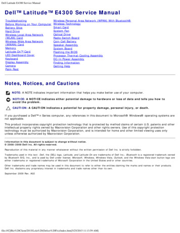
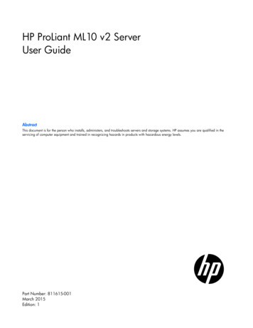
ELECTRICAL POWER QUALITY2.3.3 Swell3. Long-duration variations3.1 Interruption, sustained3.2 Under voltage3.3 Overvoltage4. Voltage unbalance5. Waveform distortion5.1 DC offset5.2 Harmonics5.3 Interharmonics5.4 Notching5.5 Noise6. Voltage fluctuations7.0 Power frequencyVariations3 s–1 min1.1–1.2 pu 1 min 1 min 1 minSteady state0.0 pu0.8-0.9 pu1.1-1.2 pu0.5–2%Steady state0–100th harmonic Steady state0–6 kHzSteady stateSteady stateBroadbandSteady state 25 HzIntermittent 10 s0–0.1%0–20%0–2%0–1%0.1–7%1.5 TransientsIt is an event that is undesirable and momentary in nature. It is the sudden change in one steadystate operating condition to another.Transients can be classified into two categories:1. Impulsive and2. Oscillatory1.5.1 Impulsive Transient An impulsive transientis a sudden non–power frequency change in the steady-statecondition of voltage, current, or both that is unidirectional in polarity (either positive ornegative). Impulsive transients are normally characterized by their rise and decay times. Due to high frequency nature, the shape of impulsive transients may be changed quicklyby circuit components and may have significant different characteristics when viewedfrom different partsof the power system. They are generally not conducted far fromthesource. Impulsive transients can excite the natural frequency of power systemcircuits andproduce oscillatory transients.Source: lightningThe following shows a typical current impulsive transient caused by lightning.Page 7
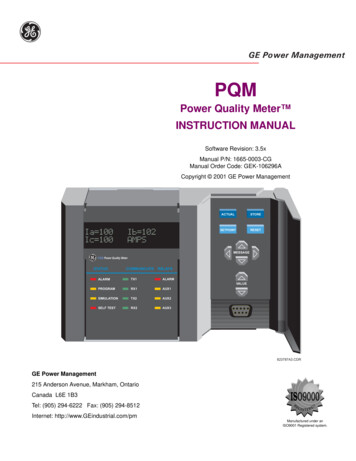
ELECTRICAL POWER QUALITY[Fig.Lightning stroke current impulsive transient]1.5.2 Oscillatory Transient An oscillatory transient is a sudden, non–power frequency change in the steady-statecondition of voltage, current, or both, that includes both positive and negative polarityvalues. Instantaneous value of oscillatory transient changes polarity rapidly.It can be classified into 3 types,1. High-frequency Transients: These have frequency components greaterthan 500kHz and a typical duration measured in microseconds (or severalcycles of theprincipal frequency).2. Medium-frequency Transients: These have frequency components between 5 and500kHz with duration measured in the tens of microseconds (or severalcycles ofthe principal frequency).3. Low-frequency Transients: These have frequency components less than 5kHz,and a duration from 0.3 to 50 ms .Sources: Back-to-back capacitor switching, Transformer energization.[ Fig. Oscillatory Transient caused due to back-to-back capacitor switching]Page 8
ELECTRICAL POWER QUALITY1.6Long-Duration Voltage VariationsWhen the rms value of voltage deviates for duration more than 1 minute, it is termed as longduration voltage variation.Sources:Load variations, System switching operation.It may be categorized into following types.1. Over Voltage: An overvoltage is an increase in the rms ac voltage greater than 110percent at the power frequency for duration longer than 1 min.Sources: (a) Overvoltage is usually the result of load switching (e.g., switchingoff a largeload or energizing a capacitor bank).(b) Incorrect tap settings on transformers can also result in system over voltages.2. Under Voltage: An under voltageis a decrease in therms ac voltage to less than 90percentat the power frequency for a duration longer than 1 min.Sources: A load switching on or a capacitor bank switching off.3. Sustained Interruptions: When the supply voltage becomes zero for a period of time inexcess of 1 min, the long-duration voltage variation is considered a sustainedinterruption.1.7 Short-Duration Voltage VariationsWhen the rms value of voltage deviates for duration less than 1 minute, it is termed as longduration voltage variation.Each type of variation can be designated as instantaneous,momentary, or temporary, dependingon its duration.It may be categorized into following types.1. Interruption:An interruption occurs when the supply voltage or load currentdecreases toless than 0.1 pu for a period of time not exceeding 1 min.Sources:Interruptions can be the result of power system faults, equipment failures, andcontrol malfunctions.2. Sags(dips): A sagis a decrease in rms voltage or currentbetween 0.1 and 0.9 pu at thepower frequency for durations from 0.5 cycle to 1 min.Sources:Voltage sags are result of system faults and also can be caused by energization ofheavy loads or starting of large motors.3. Swells: Aswell is defined as an increase to between 1.1 and 1.8 pu in rms voltage orcurrent at the power frequency for durations from 0.5 cycle to 1 min.Sources:Voltage swells occur from temporary voltage rise on the unfaulted phasesduringan SLG fault. Swells can also be caused by switching off a large load or energizinglarge capacitor bank.Page 9
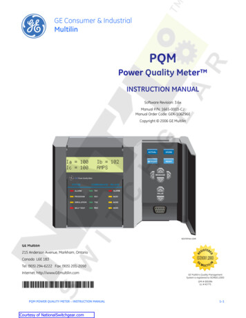
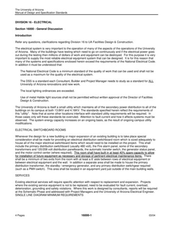
ELECTRICAL POWER QUALITY1.8 Voltage Imbalance Voltage imbalance (also called voltage unbalance) is defined as the maximum deviationfrom the average of the three-phase voltages or currents, divided by the average of thethree-phase voltages or currents, expressed in percent.The ratio of either the negative- or zero-sequence component to the positive-sequencecomponent can be used to specify the percent unbalance.The source of voltage unbalances is single-phase loads on a three-phase circuit.Voltage unbalance can also be the result of blown fuses in one phase of a three-phasecapacitor bank.Severe voltage unbalance (greater than 5 percent) can result from single-phasingconditions.1.9 Waveform DistortionWaveform distortion is defined as a steady-state deviation from an ideal sine wave of powerfrequency.There are five primary types of waveform distortion:1. DC offset2. Harmonics3. Interharmonics4. Notching5. Noise1. DC offset:The presence of a dc voltage or current in an ac power system is termed dc offset.Effects: (a) It may saturate the transformer core causing additional heating and loss oftransformer life.(b) Direct current may also cause the electrolytic erosion of grounding electrodes andother connectors.2.HarmonicsHarmonics are sinusoidal voltages or currents having frequencies that are integer multiples of thesupply frequency (fundamental frequency).Sources: Non-linear loadsTotal Harmonic Distortion is used to measure the effective value of harmonic distortion.The following figureillustrates the waveform and harmonic spectrum for a typical adjustablespeed-drive (ASD) input current.Page 10
ELECTRICAL POWER QUALITY[ Fig.Current waveform and harmonic spectrum for an ASD input current]3. InterharmonicsVoltages or currents having frequency components that are not integer multiples of the frequencyat which the supply system is designed to operate (e.g., 50 or 60 Hz) are called interharmonics.Sources: Static frequency converter, cycloconverters, induction furnaces, and arcingdevices.Power line carrier signals can also be considered as interharmonics.4. NotchingNotching is a periodic voltage disturbance caused by the normal operation of power electronicdevices when current is commutated from one phase to another.The following figure shows an example of voltage notching from a three-phase converter thatproduces continuous dc current. The notches occur when the current commutates from one phaseto another. During this period, there is a momentary short circuit between two phases, pulling thevoltage as close to zero as permitted by system impedances.Page 11
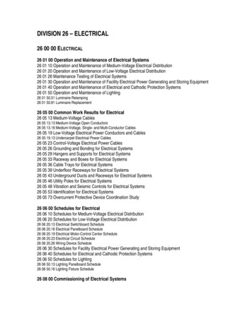
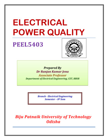
ELECTRICAL POWER QUALITY[Fig.Voltage notching caused by a three-phase converter]5. NoiseNoise is the unwanted electrical signals with broadband spectral content lower than 200 kHzsuperimposed upon the power system voltage or current in phase conductors, or found on neutralconductors or signal lines.Sources: Power electronic devices, control circuits, arcing equipment, loads with solid-staterectifiers, and switching power supplies.The problem can be mitigated by using filters, isolation transformers, and line conditioners.1.10 Voltage FluctuationVoltage fluctuations are systematic variations of the voltage envelope or a series of randomvoltage changes, the magnitude of which does not normally exceed the voltage range 0.9 to1.1 pu. Voltage fluctuations are characterized as a series of random or continuous voltagefluctuations. Loads that can exhibit continuous, rapid variations in the load current magnitude can causevoltage variations that are often referred to as flicker. The term flicker is derived from the impact of the voltage fluctuation on lamps such thatthey are perceived by the human eye to flicker. To be technically correct, voltage fluctuationis an electromagnetic phenomenon while flicker is an undesirable result of thevoltagefluctuation in some loads.The following fig. shows voltage fluctuations caused by an arc furnace operation.Page 12
ELECTRICAL POWER QUALITY[ Fig. voltage fluctuations caused by an arc furnace operation]1.11 Power Frequency VariationsPower frequency variations are defined as the deviation of the power system fundamentalfrequency from it specified nominal value (50 or 60 Hz).Sources:Due to faults on the bulk power transmission system, a large block of load beingdisconnected, or a large source of generation going off-line.On modern interconnected power system, frequency variations are rare.1.12 Power Quality TermsSome power quality terms are described below.Active filter: Consists of a number of power electronic devices for eliminating harmonicdistortion.CBEMA curve:A set of curves representing the withstand capabilities of computers in terms ofthe magnitude and duration of the voltage disturbance. It is developed by the Computer BusinessEquipment Manufacturers Association (CBEMA).It became standard for measuring theperformance of all types of equipment and power systems and is commonly referred to by thisname.CBEMAhas been replaced by the Information Technology IndustryCouncil (ITI), and anew curve has been developed that is commonly referred to as the ITI curve.Common mode voltage:The noise voltage that appears equally from current carrying conductorto ground.Coupling:A circuit element, or elements, or a network that may be considered common to theinput mesh and the output mesh and through which energy may be transferred from one toanother.Crest factor:A value reported by many power quality monitoring instruments representing theratio of the crest value of the measured waveform to the root mean square of the fundamental.For example, the crest factor of a sinusoidal wave is 1.414.Page 13
ELECTRICAL POWER QUALITYCritical load:Devices and equipment whose failure to operate satisfactorily jeopardizes thehealth or safety of personnel, and/or results in loss of function, financial loss, or damage toproperty deemed critical by the user.Current distortion:Distortion in the ac line current.Differential mode voltage:The voltage between any two of a specified set of active conductors.Distortion:Any deviation from the normal sine wave for an AC quantity.Distributed generation (DG):Generation dispersed throughout the power system as opposed tolarge, central station power plants. DG typically refers to units less than 10 megawatts (MW) insize that are interconnected with the distribution system rather than the transmission system.Dropout:A loss of equipment operation (discrete data signals) due to noise, sag, or interruption.Dropout voltage:The voltage at which a device will release to its deenergized position (for thisdocument, the voltage at which a device fails to operate).Electromagnetic Compatibility(EMC):The ability of a device, equipment, or system tofunction satisfactorily in its electromagnetic environment without introducing intolerableelectromagnetic disturbances to anything in that environment.Equipment grounding conductor:The conductor used to connect the non–current carrying partsof conduits, raceways, and equipment enclosures to the grounded conductor (neutral) and thegrounding electrode at the service equipment (main panel) or secondary of a separately derivedsystem (e.g., isolation transformer).Failure mode:The effect by which failure is observed.Fast tripping:Refers to the common utility protective relaying practice in which the circuitbreaker or line recloser operates faster than a fuse can blow.Fault:Generally refers to a short circuit on the power system.Fault, transient:A short circuit on the power system usually induced by lightning, tree branches,or animals, which can be cleared by momentarily interrupting the current.Ferro resonance:An irregular, often chaotic type of resonance that involves the nonlinearcharacteristic of iron-core (ferrous) inductors. It is nearly always undesirable when it occurs inthe power delivery system, but it is exploited in technologies such as constant-voltagetransformers to improve the power quality.Flicker:An impression of unsteadiness of visual sensation induced by a light stimulus whoseluminance or spectral distribution fluctuates with time.Frequency deviation:An increase or decrease in the power frequency. The duration of afrequency deviation can be from several cycles to several hours.Frequency response:In power quality usage, generally refers to the variation of impedance ofthe system, or a metering transducer, as a function of frequency.Fundamental (component): The component of order one (50 to 60 Hz) of the Fourier series of aperiodic quantity.Ground:A conducting connection, whether intentional or accidental, by which an electric circuitor electrical equipment is connected to the earth, or to some conducting body of relatively largeextent that serves in place of the earth. It is used for establishing and maintaining the potential ofPage 14
ELECTRICAL POWER QUALITYthe earth (or of the conducting body) or approximately that potential, on conductors connected toit, and for conducting ground currents to and from earth (or the conducting body).Ground electrode:Aconductor or group of conductors in intimate contact with the earth for thepurpose of providing a connection with the ground.Ground grid:A system of interconnected bare conductors arranged in a pattern over a specifiedarea and on or buried below the surface of the earth. The primary purpose of the ground grid is toprovide safety for workers by limiting potential differences within its perimeter to safe levels incase of high currents that could flow if the circuit being worked became energized for any reasonor if an adjacent energizedcircuit faulted. Metallic surface mats and gratings are sometimesutilized for the same purpose.This is not necessarily the same as a signal reference grid.Ground loop:Apotentially detrimental loop formed when two or more points in an electricalsystem that are nominally at ground potential are connected bya conducting path such that eitheror both points are not at the same ground potential.Ground window:The area through which all grounding conductors, including metallicraceways, enter a specific area. It is often used in communications systemsthrough which thebuilding grounding system is connected to an area that would otherwise have no groundingconnection.Harmonic (component): Integer multiple of fundamental frequency.Harmonic content:The quantity obtained by subtracting the fundamental component from analternating quantity.Harmonic distortion:Periodic distortion of the sine wave.Harmonic filter:On power systems, a device for filtering one or more harmonics from thepower system. Most are passive combinations of inductance, capacitance, and resistance. Newertechnologies include active filters that can also address reactive power needs.Harmonic number:The integral number given by the ratio of the frequency of a harmonic to thefundamental frequency.Harmonic resonance:A condition in which the power system is resonating near one of themajor harmonics being produced by nonlinear elements in thesystem, thus exacerbating theharmonic distortion.Impulse:A pulse that, for a given application, approximates a unit pulse or aDiracfunction.When used in relation to monitoring power quality, it is preferableto use the termimpulsive transient in place of impulse.Impulsive transient:A sudden, nonpower frequency change in the steady state condition ofvoltage or current that is unidirectional in polarity (primarilyeither positive or negative).Instantaneous:When used to quantify the duration of a short-duration variation as a modifier,this term refers to a time range from one-half cycle to 30 cycles of the power frequency.Instantaneous reclosing:A term commonly applied to reclosing of a utility breaker as quickly aspossible after an interrupting fault current. Typical times are 18 to 30 cycles.Page 15
ELECTRICAL POWER QUALITYInterharmonic (component):A frequency component of a periodic quantity that is not aninteger multiple of the frequency at which the supply system is designed to operate (e.g., 50 or60 Hz).Interruption, momentary (electrical power systems):An interruption of a duration limited tothe period required to restore service by automatic or supervisory controlled switching operationsor by manual switching at locations where an operator is immediately available. Such switchingoperations must be completed in a specified time not to exceed 5 min.Interruption, momentary (power quality monitoring):A type of short-duration variation. Thecomplete loss of voltage ( 0.1 pu) on one or more phase conductors for a time period between 30cycles and 3 s.Interruption, sustained (electrical power systems):Any interruption not classified as amomentary interruption.Interruption, sustained (power quality):A type of long-duration variation. The complete lossof voltage ( 0.1 pu) on one or more phase conductors for a time greater than 1 min.Interruption, temporary:A type of short-duration variation. The complete loss of voltage ( 0.1pu) on one or more phase conductors for a time period between3 s and 1 min.Inverter:A power electronic device that converts direct current to alternating current of eitherpower frequency or a frequency required by an industrialprocess. Common inverters todayemploy pulse-width modulation to create the desired frequency with minimal harmonicdistortion.Islanding:Refers to a condition in which distributed generation is isolated on a portion of theload served by the utility power system. It is usually an undesirablesituation, although there aresituations where controlled islands can improve the system reliability.Isolated ground:An insulated equipment grounding conductor run in the same conduit orraceway as the supply conductors. This conductor is insulatedfrom the metallic raceway and allground points throughout its length. It originates at an isolated ground-type receptacle orequipment input terminal block and terminates at the point where neutral and ground are bondedat the power source.Isolation:Separation of one section of a system from undesired influences of other sections.ITI curve:A set of curves published by the Information Technology Industry Council (ITI)representing the withstand capabilities of computers connected to120-V power systems in termsof the magnitude and duration of the voltage disturbance. The ITI curve replaces the curvesoriginally developed by the ITI’s predecessor organization, the Computer Business EquipmentManufacturers Association (CBEMA).Linear load:An electrical load device that, in steady-state operation, presents an essentiallyconstant load impedance to the power source throughout the cycle of applied voltage.Long-duration variation:A variation of the rms value of the voltage from nominal voltage for atime greater than 1 min. Usually further described using amodifier indicating the magnitude of avoltage variation (e.g., undervoltage, overvoltage, or voltage interruption).Page 16
ELECTRICAL POWER QUALITYLow-side surges:A term coined by distribution transformer designers to describe the currentsurge that appears to be injected into the transformer secondary terminals during a lightningstrike to grounded conductors in the vicinity.Momentary:When used to quantify the duration of a short-duration variation as a modifier,refers to a time range at the power frequency from 30 cycles to 3 s.Noise:Unwanted electrical signals that produce undesirable effects in the circuits of the controlsystems in which they occur.Nominal voltage:A nominal value assigned to a circuit or system for the purpose ofconveniently designating its voltage class.Nonlinear load:Electrical load that draws current discontinuously or whose impedance variesthroughout the cycle of the input ac voltage waveform.Normal mode voltage:Avoltage that appears between or among active circuit conductors.Notch:A switching (or other) disturbance of the normal power voltage waveform, lasting lessthan a half-cycle, which is initially of opposite polarity thanthe waveform and is thus subtractedfrom the normal waveform in terms of the peak value of the disturbance voltage. This includescomplete loss of voltage for up to a half-cycle.Oscillatory transient:A sudden, nonpower frequency change in the steady state condition ofvoltage or current that includes both positive- or negative polarity value.Overvoltage:When used to describe a specific type of long-duration variation, refers to a voltagehaving a value of at least 10 percent above the nominal voltagefor a period of time greater than 1min.Passive filter:A combination of inductors, capacitors, and resistors designed to eliminate one ormore harmonics. The most common variety is simply aninductor in series with a shunt capacitor,which short-circuits the major distorting harmonic component from the system.Phase shift:The displacement in time of one voltage waveform relative to other voltagewaveform(s).Power factor, displacement:The power factor of the fundamental frequency components of thevoltage and current waveforms.Power factor (true):The ratio of active power (watts) to apparent power (volt-amperes).Plt:The long-term flicker severity level as defined by IEC 61000-4-15, based on an observationperiod of 2 h.Pst:The short-term flicker severity level as defined by IEC 61000-4-15, based on an observationperiod of 10 min. A Pst value greater than 1.0 corresponds to the level of irritability for 50percent of the persons subjected to the measured flicker.Pulse:An abrupt variation of short duration of a physical quantity followed by a rapid return tothe initial value.Pulse Width Modulation (PWM):Acommon technique used in inverters to create an acwaveform by controlling the electronic switch to produce varying width pulses. Minimizespower frequency harmonic distortion in someapplications, but care must be taken to properlyfilter out the switching frequencies, which are commonly 3 to 6 kHz.Page 17
ELECTRICAL POWER QUALITYReclosing: The common utility practice used on overhead lines of closing the breaker within ashort time after clearing a fault, taking advantage of the fact that most faults are transient, ortemporary.Recovery time:The time interval needed for the output voltage or current to return to a valuewithin the regulation specification after a step load or linechange.Also may indicate the timeinterval required to bring a system back to
Evaluating the Economics of Different Ride-Through Alternatives, Motor Starting Sags, Utility System Fault-Clearing Issues. . 1.2.2 Medium frequency 5–500 kHz 20 μs 0–8 pu 1.2.3 High frequency 0.5–5 MHz 5 μs 0–4 pu . is defined as the maximum deviation from the average of