Transcription
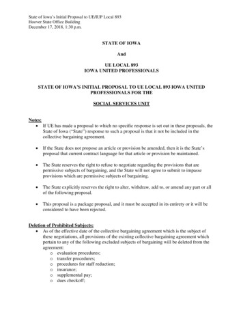
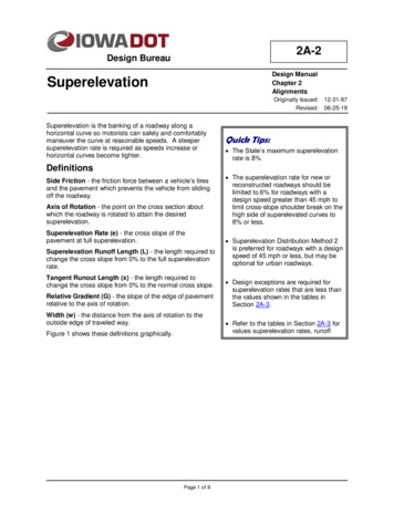
2A-2Design BureauDesign ManualChapter 2AlignmentsSuperelevationOriginally Issued: 12-31-97Revised: 06-25-19Superelevation is the banking of a roadway along ahorizontal curve so motorists can safely and comfortablymaneuver the curve at reasonable speeds. A steepersuperelevation rate is required as speeds increase orhorizontal curves become tighter.Quick Tips: The State’s maximum superelevationrate is 8%DefinitionsSide Friction - the friction force between a vehicle’s tiresand the pavement which prevents the vehicle from slidingoff the roadway.Axis of Rotation - the point on the cross section aboutwhich the roadway is rotated to attain the desiredsuperelevation.Superelevation Rate (e) - the cross slope of thepavement at full superelevation.Superelevation Runoff Length (L) - the length required tochange the cross slope from 0% to the full superelevationrate.Tangent Runout Length (x) - the length required tochange the cross slope from 0% to the normal cross slope.Relative Gradient (G) - the slope of the edge of pavementrelative to the axis of rotation.Width (w) - the distance from the axis of rotation to theoutside edge of traveled way.Figure 1 shows these definitions graphically.Page 1 of 8 The superelevation rate for new orreconstructed roadways should belimited to 6% for roadways with adesign speed greater than 45 mph tolimit cross-slope shoulder break on thehigh side of superelevated curves to8% or less. Superelevation Distribution Method 2is preferred for roadways with a designspeed of 45 mph or less, but may beoptional for urban roadways. Design exceptions are required forsuperelevation rates that are less thanthe values shown in the tables inSection 2A-3. Refer to the tables in Section 2A-3 forvalues superelevation rates, runofflengths, and runout lengths.
Chapter 2—AlignmentsSection 2A-2—SuperelevationFigure 1: Graphical definitions of superelevation terms for a two lane roadway.Superelevation Rate (e)In Iowa the superelevation rate is limited to a maximum of 8%. This reduces the risk of slow movingvehicles sliding down a superelevated roadway during winter conditions. For new construction, thesuperelevation rate is limited to 6%. This allows the shoulders to slope away from the driving laneswithout exceeding AASHTO’s 8 percent maximum value for crossover breaks. The superelevation ratefor new urban facilities is usually limited to 4% due to the frequency of cross streets, driveways, andentrances adjoining the curve, as well as the possibility of vehicles stopping on the curve at signalizedintersections. Refer to Section 1C-1 for maximum superelevation rates for 3R projects and newconstruction or reconstruction projects.Superelevation and Side Friction FactorSuperelevation rate and side friction demand, also referred to as the side friction factor, establish radii forhorizontal curves. Side friction factor represents the friction between the tires and pavement surface.This friction results in a lateral acceleration that acts upon a vehicle, and which occupants within thevehicle can feel. Like superelevation, side friction factor is limited for design speeds.Maximum Side Friction Factors (fmax )When establishing the maximum side friction factor to use for horizontal curve design, the vehicle’sneed for side friction, as well as driver comfort, must be taken into account.Side Friction (vehicle’s need)A vehicle will begin to skid when the side friction demand equals or exceeds the maximumamount of friction that can be developed between the tires and the pavement. This maximumfriction, with a factor of safety to account for variations in the speed, tire conditions, and pavementconditions, is the maximum design friction factor based upon vehicle need.Side Friction (driver comfort)Through a horizontal curve, drivers can experience a feeling of being pushed outward. If thisfeeling becomes uncomfortable, the driver will compensate by flattening out their path or braking,or both, to reduce lateral acceleration to an acceptable level. Often the driver’s comfortdetermines superelevation requirements, not the vehicle and roadway characteristics. On lowspeed roadways, drivers will accept more lateral acceleration, thus permitting a larger side frictionfactor. As speeds increase, drivers become less tolerant of lateral acceleration, requiring areduction in side friction factor.Page 2 of 8
Chapter 2—AlignmentsSection 2A-2—SuperelevationBased upon research of the above factors, AASHTO’s A Policy on Geometric Design of Highwaysand Streets lists maximum side friction factors for use in design of horizontal curves. These aresummarized in Table 1 below.Table 1: Maximum side friction factors (fmax).Design SpeedDesign 5800.08Source: AASHTO Greenbook 2011 Table 3-7.Curves should not be designed with side friction factors greater than thevalues shown in Table 1.Distribution of Superelevation (e) and Side Friction (f)Chapter 3 of AASHTO’s A Policy on Geometric Design of Highways and Streets discusses fivemethods of controlling lateral acceleration on curves using e, f, or both. Iowa DOT uses distributionMethod 2 and Method 5 depending upon the type of roadway.Low Speed RoadwaysMethod 2 is commonly used for low speed roadways. With Method 2, side friction is primarily used tocontrol lateral acceleration, and superelevation is added to radii after the maximum side friction factorhas been used. Superelevation is not needed for radii that require less than the maximum frictionfactors shown in Table 1. Distribution Method 2 increases the lateral acceleration, creating someadditional discomfort to the driver for some curves.Urban RoadwaysDrivers are willing to accept more discomfort on roadways in urban areas, due to the anticipationof more critical conditions. In addition, several factors make it difficult, if not impossible, to applysuperelevation to urban roadways: Frequency of cross streets and driveways.Vehicles stopping on curves at signalized intersections.Meeting the grade of adjacent properties.Surface drainage.Pedestrian ramps.Wider pavement area.RampsMethod 2 superelevation distribution is also well suited for curves on ramps near at-gradeterminals. Curves near at-grade terminals are usually short and drivers are traveling at reducedspeeds.The relationship between superelevation rate and minimum radius for Method 2 distribution canbe expressed as follows:R V215(0.01e fmax )where:V design speed, mph.e superelevation rate, %.fmax maximum friction factor for the design speed.Page 3 of 8
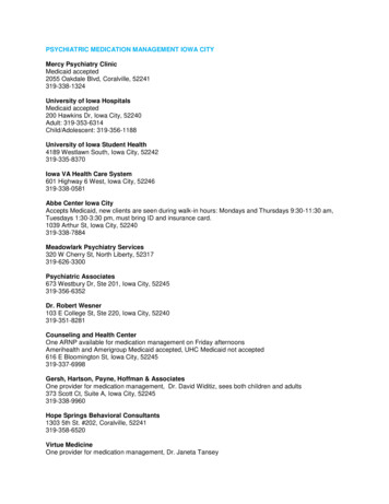
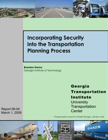
Chapter 2—AlignmentsSection 2A-2—SuperelevationR Radius of the curve, feet.Table 10 of Section 2A-3 provides minimum turning radii for various superelevation rates anddesign speeds, based upon Method 2 distribution.High Speed RoadwaysMethod 5 is used for high speed roadways. With Method 5, side friction and superelevation are bothapplied using a curvilinear relationship with the inverse of the radius.At higher speeds, drivers are less comfortable with lateral acceleration through curves. Method 5,works well for determining the distribution of superelevation and side friction for high speed roadways,because superelevation is progressively added as speed increases.Superelevation tables for high speed roadways are included in Section 2A-3. The superelevation ratefor Method 5 distribution can also be calculated manually using the equations provided in AASHTO’s A Policy on Geometric Design of Highways and Streets. An Excel file has been createdusing these formulas and is provided at the link below.Superelevation SpreadsheetNote: When calculating superelevation rates manually, round values of e up to the nearest2/10ths of a percent for new construction. AAHSTO notes precision greater than 2/10ths of apercent is not necessary.Method 5 superelevation distribution should be used for curves on ramps near free-flow terminals andcurves on directional and semi-directional ramps.Axis of RotationThe axis of rotation is the point on the cross section about which the roadway is rotated to attain thedesired superelevation. For standard situations, the axis of rotation is shown on the appropriate StandardRoad Plan (PV series).For cases not covered by the Standards, the axis of rotation should be clearly shownon the typical cross section and modified superelevation detail.Undivided RoadwaysUndivided roadways should be superelevated with the axis of rotation at the roadway’s centerline(see Figure 2).Figure 2: The axis of rotation for undivided highways.Highways with painted medians are rotated about the centerline (See Section 3E-1 for mediansdetails).Divided RoadwaysDepressed MediansMulti-lane roadways with depressed medians should be superelevated with the axis of rotation atthe median edges of the traveled way (see Figure 3). With this method, the cross section of themedian remains relatively uniform. This method is also used for two-lane roadways that willultimately become one direction of a divided highway.Page 4 of 8
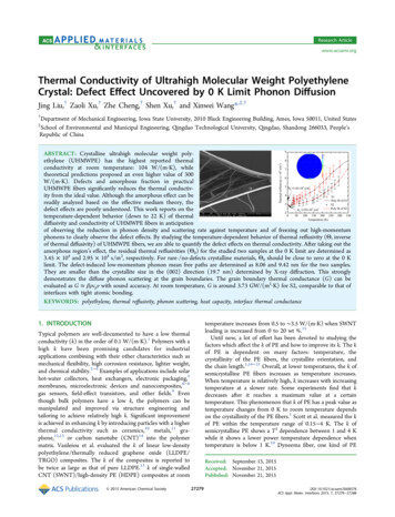
Chapter 2—AlignmentsSection 2A-2—SuperelevationFigure 3: The axis of rotation for multi-lane highways with depressed medians.Although AASHTO’s A Policy on Geometric Design of Highways and Streets suggests movingthe axis of rotation back to the roadway centerlines for wider medians, the Department’s policy isto keep the axis of rotation at the median edge of the traveled way, regardless of median width.This method may require additional earthwork, but it is preferred for reasons of constructability,simplicity of design, and the appearance of a uniform median cross section. Facilities that havewide medians with independent profile grades and/or construction centerlines may be treated astwo-lane (undivided) highways, if the resulting median cross section is acceptable.Closed MediansRoadways with closed medians (concrete barrier rail) should be superelevated with the axis ofrotation at the inside edge of the travel way with the profile grade at the centerline of the roadway.Maintaining a uniform cross-section for the median pad is preferred in order to simplify designand construction by having a roadway without a split median barrier.With this method, to maintain a uniform median pad cross-section and to maintain high side andlow side shoulder treatments described in Section 3C-3, the axis of rotation profile reference linedoes not coincide with the profile grade line. The axis of rotation profile reference line is also notshown as a horizontal line like other roadways without a closed median, See Standard Road PlanPV-305 for details.The superelevation tools through GEOPAK do not automatically createsuperelevation shapes for closed median roadways as described above. Thedesigner has to modify the superelevation input file to rotate the shouldersand pavement sections as shown on the Standard Road Plans.RampsThe axis of rotation for ramps should be at the baseline. The baseline is usually located to the rightside of the direction of travel.Superelevation TransitionsTo provide comfort and safety, superelevation should be introduced and removed uniformly. Thedistance required to transition into and out of superelevation is a function of the relative gradient, width ofpavement rotated, and superelevation rate.Relative GradientThe slope of the edge of pavement relative to the axis of rotation is referred to as “the relativegradient” (G). Figure 4 shows the relationship between relative transition length (L), superelevation(e), and pavement width (w).Figure 4: Runoff length and superelevation.Page 5 of 8
Chapter 2—AlignmentsSection 2A-2—SuperelevationFrom Figure 4, the following formula can be derived:G w eLMaximum design values for the relative gradient are shown in Table 2.Table 2: Maximum relative gradients.Design Speed(mph)1520253035404550556065707580Maximum Relative Gradient, %, (and Equivalent Maximum Relative Slopes)for profiles between the edge of a two-lane roadway and the axis of rotationMaximum Relative Gradient (G)Equivalent Maximum Relative :2330.401:2500.381:2630.351:286Source: AASHTO Greenbook 2011 Table 3-15.Superelevation Runoff LengthRunoff length is the length required to transition the outside lane(s) of the roadway from a zero (flat)cross slope to full superelevation, or vice versa. The following formula is used to determine the runofflength (L).12eL Gwhere:e full superelevation (%)G Relative gradient (%)α adjustment factor (dimensionless) to account for the number of lanes being rotated. See table3 for common values.Table 3: Adjustment factor for common roadway widths.Roadway Typetwo lane undivided (w 12 ft)four lane divided (w 24 ft)six lane divided (w 36 ft)six lane divided with inside shoulder (w 46 ft)eight lane divided (w 48 ft)eight lane divided with inside shoulder (w 58 ft)standard ramp (w 16 ft)standard loop (w 18 ft)α1.001.502.002.422.502.921.171.25The adjustment factor ( α ) for different roadway widths can be calculated manually using the followingequation:Page 6 of 8
Chapter 2—AlignmentsSection 2A-2—Superelevationα 1 0.0417(w – 12)where:w the distance from the axis of rotation to the outside edge of traveled way (ft)Runout LengthThe runout length (x) is the length required to transition the outside lane(s) of the roadway from anormal crowned section to a point where the outside lane(s) have zero (flat) cross slope, known asthe point where the roadway removes adverse crown. For consistency, the same relative gradient isused. This means the ratio of the transition length to the runoff length is the same as the ratio of thenormal cross slope to the full superelevation:x g L ewhere:x runout length, feet.L superelevation runoff length, feet.g normal cross slope, %.e full superelevation, %.From this, the runout length is determined as:x gLewhere x, L, g, and e are as explained above.Placing Superelevation TransitionHow superelevation transition is placed is critical to driver safety and comfort. If all the transition isplaced prior to the curve, the driver, while on the tangent, is forced to steer in a direction opposite thecurve to avoid drifting into opposing lanes. If all the superelevation transition is placed in the curve,the lateral acceleration the driver experiences upon entering the curve may be intolerable. Inaddition, side friction may not be sufficient to prevent the vehicle from skidding off the road. Twomethods for overcoming these problems are: Place superelevation transition in a spiral curve transition, or If a spiral curve is not used, place a portion of the superelevation transition in the tangent,and the rest in the horizontal curve.The superelevation tables in Section 2A-3 provide maximum radii for which spiral curves should beused to introduce superelevation transition. These maximums are found in AASHTO’s A Policy onGeometric Design of Highways and Streets. They are based on curve radii which suggests anoperational and safety benefit from the use of spiral transition curves. The length of the spiral shouldbe set equal to the runoff length.If a spiral curve is not used, 70 percent of the superelevation runoff length is developed on thetangent section of the roadway, with 30 percent developed on the circular curve. The variable (m) onthe Standard Road Plans represents the 30 percent of the superelevation runoff developed on thecircular curve. Superelevation at the PC or PT of a curve is equal to 0.70(e).Other proportions (60 percent to 90 percent) of the runoff length placed on the tangent section areacceptable where site conditions do not allow 70 percent. If site conditions require this, the Designermust include a modified standard road plan in the construction plan set detailing the non-standardproportion.Page 7 of 8
Chapter 2—AlignmentsSection 2A-2—SuperelevationAuxiliary LanesLow Side of Superelevated RoadwaysAcceleration lanes on the low side of a superelevated roadway should have the same cross slope asthe adjacent pavement and match the superelevation rate of transition.High Side of Superelevated RoadwaysAcceleration lanes on the highside of a superelevated roadway preferably should have the samecross slope as the adjacent pavement. Normally the cross slope of an acceleration lane will need totransition downward from the adjacent pavement near an intersection, creating a crossover crownline. Desirably the algebraic difference in the crossover crown line should be limited to 4 or 5 percent.Table 4 from Exhibit 9-49 in AASHTO’s A Policy on Geometric Design of Highways and Streets,suggests the maximum differences in crossover crown lines, related to the speed of the turningroadway at an intersection.Table 4: Maximum Algebraic Difference in Cross Slope at Turning Roadway Terminals.Design speed of exit orentrance curve (mph)Maximum algebraicdifference in cross slopeat crossover line (%)20 and under5.0 to 8.025 and 305.0 to 6.035 and over4.0 to 5.0Source: AASHTO Greenbook 2011 Table 9-20.Cross Slope TransitionPreferably the cross slope rate of transition for the auxiliary lane should equal the cross slope rate oftransition of the adjacent pavement. In areas near an intersection a faster rate of transition may bedesirable.The designer should refer to Table 2 for the maximum grade change in the profile edge of pavementto determine the maximum rate of transition per station.For example: If the design speed of the limiting curve of a turning roadway has a design speed of 15mph, the relative gradient of the edge of pavement is 0.78 (1:128). This results in a rate of change incross slope of 6.5% for a 12 foot lane per station (100 ft).L G 100 0.78 6.5%w12Shoulder Treatment in Superelevated CurvesSee Section 3C-3.Page 8 of 8
Chronology of Changes to Design Manual Section:002A-002 Superelevation6/25/2019RevisedUpdated hyperlinks.Updated header logo and text.7/18/2013RevisedAdded Quick Tips. Clarified Method 2 is preferred for roads (rural and urban) with design speeds of 45 mph orless (including ramps). Also noted design exceptions are required for e less than values in Section 2A-3.12/10/2010RevisedRewrote auxillary lanes section to comply with AASHTO crown break guidance.5/28/2010RevisedUpdate standard numbers
2A-2 Design Manual Chapter 2 Alignments Originally Issued: 12-31-97 Revised: 06-25-19 Design Bureau Quick Tips: The State’s maximum superelevation rate is 8% The superelevation rate for new or reconstructed roadways should be limited to 6% for roadways with a design speed greater t