Transcription
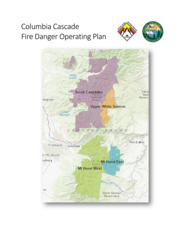
Fire4100ES-S1 Fire Indicator PanelInstallation & ation &MaintenanceManualManualLT0394Issue 1.9
Copyrights and Trademarks 2006, 2014 Tyco Australia Pty Limited. All Rights Reserved.All specifications and other information shown were current as of document revision date,and are subject to change without notice.Tyco, Simplex, the Simplex logo, MAPNET II, IDNet, TrueAlarm, SmartSync,WALKTEST, MINIPLEX, and TrueAlert are trademarks of Tyco International ServicesAG or its affiliates in the U.S. and/or other countries. VESDA is a trademark of Xtralis.Simplex fire alarm technology is protected by the following U.S. Patent Numbers:TrueAlarm analog smoke detection: 5,155,468; 5,173,683 and 5,543,777. IDNet andMAPNET II addressable communications; 4,796,025. TrueAlert addressable notification;6,313,744 and 6,426,697. SmartSync horn/strobe control; 6,281,789.ApprovalsAustralian Standard AS 4428.1ActivFire Listing Number afp1682ManufactureThe 4100ES-S1 is a Fire Indicator Panel manufactured by Tyco Fire Protection Productsfor:Tyco Services Fire & Safety47 Gilby RoadNotting HillVIC 3168AUSTRALIAPhone : (03) 9538-7220Fax :(03) 9538-7255Product / SiteNameSerial #Manufacture Dateiii
Non-Disclosure AgreementTyco (THE COMPANY) and the User of this/these document(s) desire to shareproprietary technical information concerning electronic systems.For this reason the company is disclosing to the User information in the form of this/thesedocument(s). In as much as the company considers this information to be proprietary anddesires that it be maintained in confidence, it is hereby agreed by the User that suchinformation shall be maintained in confidence by the User for a period of TEN YEARSafter the issue date and only be used for the purpose for which it was supplied.During this period, the User shall not divulge such information to any third party withoutthe prior written consent of the company and shall take reasonable efforts to prevent anyunauthorised disclosure by its employees. However, the User shall not be required tokeep such information in confidence if it was in their possession prior to its receipt fromthe company; if it is or becomes public knowledge without the fault of the User; or theinformation becomes available on an unrestricted basis from a third party having a legalright to disclose such information.The User's receipt and retention of this information constitutes acceptance of these terms.This information is copyright and shall not be reproduced in any form whatsoever.End User Liability DisclaimerThe 4100ES-S1 Fire Indicator Panel provides a configuration programming facility,which may be accessed via a programming computer using a “dongle”. Because thisprogramming facility allows the user to define in detail the operation of the 4100ES-S1System being customised, changes may be made by the user that prevent this installationfrom meeting statutory requirements.The Company, therefore cannot accept any responsibility as to the suitability of thefunctions generated by the user using this programming facility.iv
Model Number & Firmware RevisionThis manual applies to product with the following:Model number :4100ES-S1Firmware revision : 1.02.04 and onDocumentDocument Name :LT0394 4100ES-S1 Installation & Maintenance ManualIssue :V1.924 Feb 2015Amendment Log5 July 2006Issue 1.0Original based on LT0350 1.0.76 October 2006 Issue 1.1References to LT0432 and 1976-181 Wiring Diagramsadded.30 Nov. 2006Issue 1.2Updated drawings 1976-181 Sheets 102, 203, 500.23 Jan. 2007Issue 1.3Changes to T-GEN connection, checking system wiring.21 Feb. 2007Issue 1.4Changes to AIU/PPU Brigade Interface mounting14 June 2012Issue 1.5Changes for 4100ES introduction7 March 2014Issue 1.6Update to SPS Troubleshooting, added Install Mode3 June 2014Issue 1.7Drg 1976-174 sheet 4 removed.29 Jan 2015Issue 1.8Battery charger adjustment updated.24 Feb 2015Issue 1.9Updated drawing 1976-181 Sheet 411.v
Cautions, Warnings, and Regulatory InformationREAD AND SAVE THESE INSTRUCTIONS. Follow the instructions in thisinstallation manual. These instructions must be followed to avoid damage to this productand associated equipment. Product operation and reliability depends upon properinstallation.DO NOT INSTALL ANY SIMPLEX PRODUCT THAT APPEARS DAMAGED.Upon unpacking your Simplex product, inspect the contents of the carton for shippingdamage. If damage is apparent, immediately file a claim with the carrier and notify yourSimplex product supplier.SAFETY HAZARD - The 4100ES-S1 CPU Card includes a lithium battery. There isdanger of explosion if the battery is incorrectly replaced. Replace only with the sameor equivalent type recommended by the manufacturer. Dispose of used batteries accordingto the manufacturer’s instructions.ELECTRICAL HAZARD - Disconnect electrical field power when making any internaladjustments or repairs. All repairs should be performed by a representative or authorizedagent of your local Simplex product supplier.STATIC HAZARD - Static electricity can damage components. Therefore, handle asfollows: Ground yourself before opening or installing components (use a suitable wrist-strapand cable clipped to the frame or an earth connection of the 4100ES-S1). Prior to installation, keep components wrapped in anti-static material at all times.EYE SAFETY HAZARD - Under certain fibre optic application conditions, the opticaloutput of this device may exceed eye safety limits. Do not use magnification (such as amicroscope or other focusing equipment) when viewing the output of this device.RADIO FREQUENCY ENERGY - This equipment generates, uses, and can radiateradio frequency energy and if not installed and used in accordance with the instructionmanual, may cause interference to radio communications. It has been tested and found tocomply with the limits defined in AS 4428.0-1997 and Amendment 1:2002.SYSTEM REACCEPTANCE TEST AFTER SOFTWARE CHANGES - To ensureproper system operation, this product must be tested in accordance with AS 1670 afterany programming operation or change in site-specific software. Reacceptance testing isrequired after any change, addition or deletion of system components, or after anymodification, repair or adjustment to system hardware or wiring.IMPORTANT: Verify 4100ES Programmer, Executive, and Slave Softwarecompatibility when installing or replacing system components. Refer to the relevantProduct Bulletins from Simplex Fire Products Australia (www.simplexfire.com.au) forcompatibility information.vi
Table of Contents{ XE "Table of Contents" }Copyrights and Trademarks. iiiApprovals. iiiManufacture. iiiProduct / Site . iiiNon-Disclosure Agreement . ivEnd User Liability Disclaimer . ivModel Number & Firmware Revision .vDocument .vAmendment Log .vCautions, Warnings, and Regulatory Information. viTable of Contents . viiList of Figures . xiiiList of Tables . xivChapter 1 Introduction to the 4100ES-S1 Fire Alarm System . 1-1Introduction . 1-1In this Chapter . 1-1Basic Configuration. 1-2Overview . 1-2System Design . 1-24100ES-S1 Part Codes . 1-3Overview . 1-3Assemblies, Cards & & Modules . 1-3Kits. 1-3Labels (expansion/spares) . 1-4Looms (expansion/spares) . 1-44100 Part Codes (Non-4100ES) . 1-4Glossary . 1-5Chapter 2 Installing 4100ES-S1 Components . 2-1Introduction . 2-1In this Chapter . 2-1Introduction to 4100ES-S1 Cabinet . 2-2Overview . 2-2Bays. 2-2CPU Motherboard . 2-3CPU Card . 2-4CPU Card LEDs . 2-5Operator Interface . 2-6Additional CPU Motherboard Modules . 2-6System Power Supply (SPS) . 2-6The Power Distribution Interface (PDI). 2-8Mains Outlet. 2-8vii
Step 1. Mounting Cabinets . 2-9Overview . 2-9Step 2. Mounting Card Bays to Cabinets . 2-9Overview . 2-9Step 3. Configuring Cards . 2-9Overview . 2-9CPU Motherboard Configuration . 2-9CPU Daughter Card Configuration . 2-10SPS Configuration . 2-10PDI Configuration . 2-10Configuring Other Cards . 2-10Step 4. Interconnecting Modules and Bays . 2-11Overview . 2-11Guidelines . 2-11Card Interconnections in the CPU Bay. 2-11Card Interconnections Within Expansion Bay . 2-11Basic Bay-To-Bay Interconnections . 2-11Connecting to Motherboards . 2-12Step 5. Installing Modules into Expansion Bays. 2-13Overview . 2-13Placement Guidelines . 2-13Installing 4” X 5” Cards . 2-15Installing Motherboards. 2-16Step 6. Installing LED/Switch Modules into Expansion Bays . 2-17Overview . 2-17The LED/Switch User Interface . 2-18LED/Switch Controller Card . 2-18Configuring the LED/Switch Controller Card . 2-19Mounting LED/Switch Modules to the Expansion Bay . 2-19Mounting the Additional LED/ Switch Controller Card . 2-20LED/Switch Modules . 2-21Wiring Instructions . 2-214100ES Fan Control Module. 2-22Overview . 2-22Labelling . 2-22Mounting & Connection. 2-22Programming . 2-22Installing Other Modules . 2-24Chapter 3 Networking . 3-1Introduction . 3-1In this Chapter . 3-1Network Configuration . 3-2Overview . 3-2Ring and Star Configurations . 3-2Connecting Loops . 3-3System Design . 3-3Getting Started . 3-4Overview . 3-4Introduction to the 4100 Network Interface Card (NIC) . 3-4Overview . 3-4Network Module Illustrations . 3-5NIC Card LED Indications . 3-5viii
NIC Media Cards . 3-6Requirements and Limitations. 3-7Step 1. Configuring Network Cards . 3-7Overview . 3-7CPU Motherboard Jumper Settings . 3-7NIC Card Address Setting . 3-7NIC Card Jumper Settings . 3-8Wired Media Card Jumper Settings . 3-8Step 2. Mounting Media Cards to the NIC . 3-9Overview . 3-9Media Card Mounting. 3-9Step 3. Mounting Network Cards in the 4100ES-S1 . 3-9Step 4. Wiring Network Cards. 3-10Overview . 3-10Wiring Guidelines . 3-10Wiring Distances . 3-11Fibre-Optic Wiring . 3-12Fibre Optic Connection Types. 3-124190-9010 Coupler Requirements . 3-13Wiring with the Wired Media Card . 3-14Loop Wiring, mixed Fibre and Cable . 3-17Chapter 4 The System Power Supply & Alarm Relay Card . 4-1Introduction . 4-1In this Chapter . 4-1SPS Specifications . 4-2Input/Output/BatterySpecifications . 4-2SPS Current Consumption . 4-3SPS Adjustments . 4-4Adjusting Voltages . 4-4Setting Jumpers and DIP Switches . 4-4SPS LED Indications . 4-5Status LEDs . 4-5Troubleshooting an SPS . 4-6Overview . 4-6“IDNet Power Monitor Trouble” . 4-6“Extra Device” . 4-6“Class A Trouble” . 4-6“Earth Fault Search”. 4-6“Short Circuit”. 4-6“Channel Fail” . 4-6“No Answer/ Bad Answer” . 4-6“Output Abnormal” . 4-6Noisy Buzz from the SPS . 4-6The Alarm Relay Card . 4-7Overview . 4-7Mounting (factory installed) . 4-7Configuration . 4-8Notes . 4-8Warning . 4-8Specification . 4-8Brigade Interfaces . 4-9Overview . 4-9ix
Format . 4-9Applications . 4-9Kit Contents . 4-9Door Mounting . 4-9General Wiring . 4-10Brigade Interfaces, Continued . 4-10AIU/PPU Mounting . 4-10AIU/PPU Wiring . 4-10ASE Mounting . 4-10ASE Wiring . 4-10Chapter 5 SPS Field Wiring (4100ES-S1). 5-1Introduction . 5-1In this Chapter . 5-1General Field Wiring Guidelines . 5-2General Guidelines . 5-2SPS NAC Field Wiring Guidelines . 5-3Overview . 5-3Guidelines . 5-3Allocations . 5-3Class A (loop) NAC Wiring . 5-4Class B (string) NAC Wiring . 5-5Power Supply Wiring Distances . 5-6Overview . 5-6Class A NAC Wiring Table . 5-6Class B NAC Wiring Table . 5-7Using T-GEN 50 with 4100ES-S1 . 5-8Overview . 5-8Powering the T-GEN 50 . 5-8Controlling a T-GEN 50 with a Relay Module . 5-10T-GEN 50 Setting for Relay Operation . 5-11Controlling a T-GEN 50 from a NAC Output . 5-12T-GEN 50 Settings for NAC Operation. 5-13Fitting an Evacuation Control . 5-14Fitting a PA Microphone . 5-14100V Speaker Wiring . 5-15SPS Auxiliary Power Wiring . 5-16Overview . 5-16Guidelines . 5-16Wiring . 5-17SPS Relay Wiring . 5-18Overview . 5-18Aux 1 Relay . 5-18Alarm Relay Card . 5-18SPS IDNet Wiring . 5-19Overview . 5-19IDNet Wiring . 5-19Guidelines . 5-19Notes . 5-20Class A (loop) Wiring . 5-21Class B (string) Wiring . 5-22x
Chapter 6 Using Install Mode. 6-1Introduction . 6-1In this Chapter . 6-1Adding Devices to Install Mode. 6-2Adding a Single Device to Install Mode
v Model Number & Firmware Revision This manual applies to product with the following: Model number : 4100ES-S1 Firmware revision : 1.02.04 and on