Transcription
DESIGN RECOMMENDATION FORSTORAGE TANKS AND THEIR SUPPORTSWITH EMPHASIS ON SEISMIC DESIGN(2010 EDITION)ARCHITECTURAL INSTITUTE OF JAPAN
ForewordThe Architectural Institute of Japan set up a “Sub-Committee for Design of Storage Tanks” toprovide a recommendation of the seismic design for the various types of storage tanks incommon use throughout Japan. The Sub-Committee first published “Design Recommendationfor Storage Tanks and Their Supports” in 1984, and amended it in the 1990, 1996 and 2010publications. This current revised recommendation provides bulk material pressures for silosand further guidance on seismic design methods for storage tanks based on the horizontal loadcarrying capacity in the structure.It is envisaged by publishing the English version of “Design Recommendation for StorageTanks and Their Supports” that the above unique design recommendation will be promoted tothe overseas countries who are concerned on the design of storage tanks and the activities ofthe Architectural Institute of Japan will be introduced them too. It is addressed how thisrecommendation is in an advanced standard in terms of the theory of the restoring forcecharacteristics of the structure considering the Elephant Foot Bulge (EFB), the effect of theuplifting tank and the plastic deformation of the bottom plate at the shell-to-bottom juncture inthe event of earthquake, the design spectrum for sloshing in tanks, the design pressure for silos,and the design methods for the under-ground storage tanks as well. The body of therecommendation was completely translated into English but the translation of the commentarywas limited to the minimum necessary parts for understanding and utilising the theories andequations in the body. The sections 2.7 Timbers and 4.9 Wooden Storage Tanks are omitted asthey are not common in overseas countries. Listing of some Japanese references are omittedand some new references are added in this English version.It is worthy of note that the contents of this recommendation have been verified and theirefficacy confirmed by reference to data obtained from the tanks and silos damaged duringrecent earthquakes in Japan, including the Hanshin-Awaji Great Earthquake in 1995 and theNiigataken Chuetu-oki Earthquake in 2007.i
IntroductionThere are several types of storage tanks, e.g., above-ground, flat-bottomed, cylindrical tanks forthe storage of refrigerated liquefied gases, petroleum, etc., steel or concrete silos for the storageof coke, coal, grains, etc., steel, aluminium, concrete or FRP tanks including elevated tanks forthe storage of water, spherical tanks (pressure vessels) for the storage of high pressure liquefiedgases, and under-ground tanks for the storage of water and oil. The trend in recent years is forlarger tanks, and as such the seismic design for these larger storage tanks has become moreimportant in terms of safety and the environmental impact on society as a whole.The failure mode of the storage tank subjected to a seismic force varies in each structural type,with the structural characteristic coefficient (Ds) being derived from the relationship betweenthe failure mode and the seismic energy transferred to, and accumulated in the structure. Acylindrical steel tank is the most common form of storage tank and its normal failure mode is abuckling of the cylindrical shell, either in the so called Elephant Foot Bulge (EFB), or asDiamond Pattern Buckling (DPB). The Ds value was originally calculated with reference toexperimental data obtained from cylindrical shell buckling, but was later re-assessed andmodified based on the restoring force characteristics of the structure after buckling. Thosephenomena at the Hanshin-Awaji Great Earthquake and the Niigataken Chuetu-oki Earthquakewere the live data to let us review the Ds value. For the EFB, which is the typical bucklingmode of a cylindrical shell storage tank for petroleum, liquefied hydrocarbon gases, etc., itbecame possible to ascertain the buckling strength by experiments on a cylindrical shell byapplying an internal hydrodynamic pressure, an axial compressive force, and a shear forcesimultaneously. Details of these experiments are given in Chapter 3.The seismic design calculations for other types of storage tanks have been similarly reviewedand amended to take into account data obtained from recent experience and experiments.Design recommendation for sloshing phenomena in tanks has been added in this publication.Design spectra for sloshing, spectra for long period range in other words, damping ratios forthe sloshing phenomena and pressures by the sloshing on the tank roof have been presented.For above-ground vertical cylindrical storage tanks without any restraining element, such asanchor bolts or straps, to prevent any overturning moment, only the bending resistance due tothe uplift of the rim of bottom plate exists. This recommendation shows how to evaluate theenergy absorption value given by plasticity of the uplifted bottom plate for unanchored tanks,as well as the Ds value of an anchored cylindrical steel-wall tank.As the number of smaller under-ground tanks used for the storage of water and fuel isincreasing in Japan, the Sub-committee has added them in the scope of the recommendationand provided a framework for the seismic design of under-ground tanks. The recommendationhas accordingly included a new response displacement method and a new earth pressurecalculation method, taking into account the design methods adopted by the civil engineeringfraternity.For silo design, additional local pressure which depends on eccentricity of discharge outlet, andequations which give approximate stress produced by this pressure are given in this 2010 publication.August 2011Sub-committee for Design of Storage TanksThe Architectural Institute of Japanii
COMMITTEE FOR STRUCTURES (2010)ChairmanSecretariesMembersMasayoshi NAKASHIMAHiroshi OHMORIHiroshi KURAMOTO(Omitted)Kenji MIURASUB-COMMITTEE FOR DESIG OF STORAGE TA KS (2010)ChairmanSecretariesMembersYukio NAITONobuyuki KOBAYASHIHiroshi AKIYAMAHitoshi KUWAMURAHideo NISHIGUCHIYutaka YAMANAKAHitoshi HIROSEYasushi UEMATSUMinoru KOYAMAKatsu-ichiro HIJIKATAJun YOSHIDAToshio OKOSHIKouichi SHIBATAHiroaki MORIWORKI G GROUP FOR SEISMIC LOAD A D RESPO SEESTIMATIO OF STORAGE TA KS (2008)ChairmanSecretaryMembersYukio NAITONobuyuki KOBAYASHITokio ISHIKAWANobuo NAKAIKatsu-ichiro HIJIKATAHitoshi HIROSEShinsaku ZAMAHideo NISHIGUCHITetsuya MATSUIiiiHitoshi SEYA
Table of Contents1General ------------------------------- 11.1 Scope --------------------------------- 11.2 Notations ----------------------------- 122.12.22.32.42.52.62.7Materials ----------------------------- 3Scope --------------------------------- 3Steels --------------------------------- 3Stainless Steels ---------------------- 4Concrete ------------------------------ 4Aluminium Alloys ------------------ 4FRP ----------------------------------- 5Timber -------------------------------- 63.13.23.33.43.53.63.73.8Design Loads ------------------------ 9General ------------------------------- 9Dead Loads -------------------------- 9Live Loads --------------------------- 9Snow ------------------------------- 9Wind Loads ------------------------ 10Seismic Loads --------------------- 10Design of Cylindrical Metal Shell Wall Against Buckling ------------------- 23Earth Pressures -------------------- 414.14.24.34.44.54.64.74.84.9Water Tanks ----------------------Scope ------------------------------Structural Design ----------------Reinforced Concrete Water Tanks stressed Concrete Water Tanks ---------------------------------------------Steel Water Tanks ---------------Stainless Steel Water Tanks ----Aluminium Alloy Water Tanks FRP Water Tanks ----------------Wooden Water Tanks -------------------------------Scope ------------------------------Structural Design ----------------Reinforced Concrete Silos ------Steel Silos --------------------------51515260603456Seismic Design of Supporting Structures for Spherical Tanks -------------------- 626.1 Scope ------------------------------- 626.2 Physical Properties and Allowable Stresses ------------------------------------- 636.3 Seismic Design -------------------- 64iv
7Seismic Design of Above-ground, Vertical, Cylindrical Storage Tanks ---------- 767.1 Scope ------------------------------- 767.2 Seismic Loads --------------------- 807.3 Evaluation of Seismic --------- 958Seismic Design of Under-ground Storage Tanks ---------------------------------- 1008.1 Scope ------------------------------ 1008.2 Seismic Design ------------------- 1008.3 Evaluation of Seismic -------- 104Appendix AA1A2A3A4Appendix BDesign and Calculation Examples ----------------------------------- 106Steel Water Tower Tanks --------------------------------------------- 106Steel Silo -------------- 120Supporting Structures for Spherical Tanks ----------------------------- 149Above-ground, Vertical, Cylindrical Storage Tanks ------------------ 154Assessment of Seismic Designs for Under-groundStorage Tanks --------- 160v
1.General1.1ScopeThis Design Recommendation is applied to the structural design of water storagetanks, silos, spherical storage tanks (pressure vessels), flat-bottomed, cylindricalabove-ground storage tanks and under-ground storage ---Commentary:This Design Recommendation is applied to the structural design, mainly the seismic design, ofwater storage tanks, silos, spherical storage tanks (pressure vessels), flat-bottomed, cylindrical,above-ground storage tanks and under-ground storage tanks. As common requirements chapter 2calls for material specifications which are applicable to the above -mentioned tanks, and chapter 3calls for loads and buckling designs. Chapter 3 especially highlights the modified seismiccoefficient method and the modal analysis as approved evaluation methods of seismic design basedon the reference design acceleration response spectrum and the structural characteristic coefficientDs. The seismic design method adopted in the Recommendation is the allowable stress methodmodified with B, the ratio of the horizontal load-carrying capacity in the structure to the short-termallowable yield strength. The design for each tank is described in chapter 4 and onwards. Chapters4 and 5 call for general requirements of structural design of tanks and their supporting structuresfor water storage tanks and silos, respectively. Chapters 6 calls for requirements of seismic designonly for supporting structures of spherical storage tanks. Chapters 7 and 8 calls for requirementsof flat-bottomed, cylindrical above-ground storage tanks and under-ground storage tanks,respectively.Examples of design procedure for each type of tanks in chapters 4 through 8 are included inappendices.1.2otationsThe following notations are applicable as common notations through the chapters inthis Recommendation, and each chapter includes some additional notations to bespecifically used in the chapter.BCCjDsDhDηEFb fcrc fcrs fcrghIjKChapter2ratio of the horizontal load-carrying capacity in the structure to the short-termallowable yield strengthdesign yield shear force coefficientdesign yield shear force coefficient at the j-th natural modestructural characteristic coefficient Dh Dηcoefficient determined by the damping of the structurecoefficient determined by the ductility of the structureYoung’s modulus (N/mm2)yield strength (N/ mm2)allowable bending stress in the cylindrical wall (N/mm2)allowable compressive stress in the cylindrical wall (N/mm2)allowable shear stress in the cylindrical wall (N/mm2)acceleration of gravity ( 9.8m/s2)damping ratioimportance factororder of natural frequencylateral design seismic coefficient1
z)uijWWiZsσbσcσhτChapter2lateral design seismic coefficient in the groundvertical design seismic coefficient in the groundlateral design seismic coefficient at the ground surfacelateral design seismic coefficient at the bedrock surfacethe maximum number of vibration modes which largely influence to seismicresponsestotal number of mass pointsdesign yield shear force at the base of the structure (N)design shear force imposed just below the i-th mass in case that the structure isassumed the n-th lumped mass vibration system (N)ground amplification factorradius of cylindrical tank (mm)design velocity response spectrum (m/s)design acceleration response spectrum (m/s2)acceleration response at the first natural period (m/s2)acceleration response at the j-th natural period (m/s2)design velocity response at the first natural period in the sloshing mode (m/s)the first natural period of the structure (s)j-th natural period of the structure (s)critical period determined by the ground classification (s)horizontal displacement at the depth z from the ground surface (m)vertical displacement at the depth z from the ground surface (m)j-th natural mode at the i-th massdesign weight imposed on the base of the structure (N)weight of the i-th mass (N)seismic zoning factorbending stress in the cylindrical wall (N/mm2)average compressive stress in the cylindrical wall (N/mm2)average hoop tensile stress in the cylindrical wall (N/mm2)shear stress in the cylindrical wall (N/mm2)2
2.Materials2.1ScopeThis chapter calls for the recommended materials used in the tanks and their supports.Allowable stresses of the materials are determined in accordance with therecommended method set up in each chapter for each type of storage tank.2.2SteelsSteel materials listed in Table 2.1 should apply for.Table 2.1 Specifications for SteelsSpecificationJIS G 3136JIS G 3101JIS G 3106JIS G 3444JIS G 3466JIS G 5101JIS G 3201JIS G 3115JIS G 3120JIS G 3126JIS B 1186JIS Z 3211JIS Z 3212JIS Z 3351JIS Z 3352JIS G 3112JIS G 3117JIS G 3551JIS G 3536JIS G 3538JIS G 3109Chapter2Type of steel GradesRolled Steels for Building Structure; SN400A/B/C, SN490B/CRolled Steels for General Structure; SS400, SS490, SS540Rolled Steels for Welded Structure; SM400A/B/C, SM490A/B/C,SM490YA/YB, SM520B/C, SM570Carbon Steel Tubes for General Structural Purposes; STK400,STK490Carbon Steel Square Pipes for General Structural Purposes;STKR400, STKR490Carbon Steel CastingsCarbon Steel Forgings for General UseSteel Plates for Pressure Vessels for Intermediate TemperatureService; SPV235, SPV315, SPV355, SPV450, SPV490Manganese-Molybdenum and Manganese-Molybdenum-NickelAlloy Steel Plates Quenched and Tempered for Pressure Vessels;SQV1A/1B, SQV 2A/2B, SQV 3A/3BCarbon Steel Plates for Pressure Vessels for Low TemperatureService; SLA235A/B, SLA325A/B, SLA365Sets of High Strength Hexagon Bolt, Hexagon Nut and PlainWashers for Friction Grip JointsCovered Electrodes for Mild SteelCovered Electrodes for High Tensile Strength SteelSubmerged Arc Welding Solid Wires for Carbon Steel and LowAlloy SteelSubmerged Arc Welding Fluxes for Carbon Steel and Low AlloySteelSteel Bars for Concrete ReinforcementRerolled Steel Bars for Concrete ReinforcementWelded Steel Wires and Bar FabricsUncoated Stress-Relieved Steel Wires and Strands forPrestressed ConcreteHard Drawn Steel Wires for Prestressed ConcreteSteel Bars for Prestressed ConcreteJIS : Japanese Industrial Standards3
2.3Stainless SteelsStainless steel materials listed in Table 2.2 should apply for.Table 2.2 Specifications for Stainless SteelsSpecificationJIS G 4304JIS G 4305JIS G 3601JIS G 3459JIS Z 3221JIS Z 3321Type of steel GradesHot Rolled Stainless Steel Plates, Sheets and Strips; SUS304,SUS304L, SUS316, SUS316L, SUS444, SUS329 J 4 LCold Rolled Stainless Steel Plates, Sheets and Strips; SUS304,SUS304L, SUS316, SUS316L, SUS444, SUS329 J 4 LStainless Clad Steels; SUS304, SUS304L, SUS316, SUS316L,SUS444Stainless Steel Pipes; SUS304TP, SUS304LTP, SUS316TP,SUS316LTP, SUS444TP, SUS329 J 4 LTPStainless Steel Covered ElectrodesStainless Steel, Wire Rods and Solid Wires2.4Concrete2.4.1Concrete materials should comply with JASS 5 (Japanese Architectural StandardSpecifications and Commentary for Reinforced Concrete Works (2003)) 5.4“Concrete Materials” except that par. 5N.13.3 “Pre-stressed Concrete” of JASS 5N“Reinforced Concrete Work at Nuclear Power Plants (2001)” should apply for prestressed concrete.2.4.2Quality of concrete materials should comply with Table 2.3 and below.-JASS 5.5 “Mixing Proportion”JASS 5.6 “Production of Concrete”JASS 5.7 “Transportation and Placement”JASS 5.8 “Curing” etc.JASS 5N.13.3 “Pre-stressed Concrete” should apply for pre-stressed concrete.Table 2.3 Specifications for Concrete Materials2.5SpecificationMinimum Value of Fc(N/mm2)Normal WeightConcrete18AggregateCoarseGravel or CrushedStoneFineSand or CrushedSandAluminium AlloysAluminium alloys used for structural members should be selected from thoseChapter24
designated in Table 2.5 which are in accordance with the specifications of JapaneseIndustrial Standards in Table 2.4.Table 2.4 Aluminium and Aluminium Alloy MaterialsSpecificationJIS H 4000TitleAluminium and Aluminium Alloy Sheets and Plates, Strips andCoiled SheetsAluminium and Aluminium Alloy Rods, Bars and WiresAluminium and Aluminium Alloy Extruded Tubes and Colddrawn TubesAluminium and Aluminium Alloy Welded Pipes and TubesAluminium and Aluminium Alloy Extruded ShapeAluminium and Aluminium Alloy ForgingsAluminium Alloy CastingsAluminium and Aluminium Alloy Welding Rods and WiresJIS H 4040JIS H 4080JIS H 4090JIS H 4100JIS H 4140JIS H 5202JIS Z 3232Table 2.5 Grades of Aluminium Alloy MaterialsA 1060A 1070A 1080A 1100A 1200A 3003A 3203A 5052A 5056A 5083A 5086A 5154A 5254A 5454A 5652A 6061-T4A 6061-T6A 6063-T5A 6063-T6A 7 N 01-T4A 7 N 01-T6A 7003-T52.6FRP2.6.1Resins used for FRP (Fibre Reinforced Plastics) materials should be equal to orbetter than the quality of the UP-G (Unsaturated Polyester Resin-Gneral) specified inthe Japanese Industrial Standard JIS K 6919 (Liquid unsaturated polyester resins forfibre reinforced plastics), and should have excellent weather and water resistantproperties.2.6.2Glass fibre used for FRP materials should be of the no alkali glass type in accordancewith the Japanese Industrial Standards indicated in Table 2.6. Any additionalprocessed glass fibres should also be manufactured using these fibres as rawmaterials.Table 2.6 Types of glass fibre for FRPSpecificationJIS R 3411JIS R 3412JIS R 3413JIS R 3415JIS R 3416JIS R 3417Chapter2TypeTextile glass chopped strand matsTextile glass rovingsTextile glass yarnsTextile glass tapesFinished textile glass fabricsWoven roving glass fabrics5
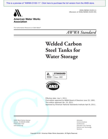
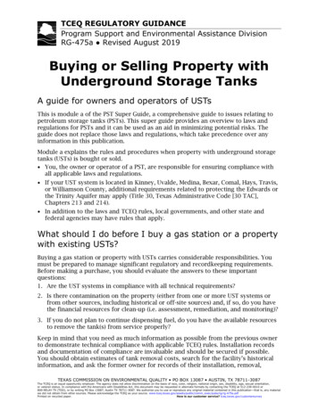
2.6.3FRP materials should be processed using the resins and glass fibres specified above,and by adding any necessary fillers, coloring agents, artificial fibres, etc., as requiredto ensure that the performance requirements stipulated in Table 2.7 are satisfied.Table 2.7 Physical Properties of FRP MaterialsPropertyTensile strengthFlexural strengthFlexural modulusGlass contentBarcol hardnessWater absorption2.7Performance 59N/mm2 78N/mm2 5.9 103 N/mm2 25wt% 30 1.0%Testing MethodJIS K 7054JIS K 7055JIS K 7055JIS K 7052JIS K 7060JIS K 6919TimberThis section is omitted in this English version.Commentary1.Component Materials of FRPFRP basically consists of a fibre reinforcement in a resin matrix. FRP used for water tanks, use acompound resin consisting of hardening agents, colouring agents, mineral fillers, etc., in anunsaturated polyester resin. The fibre reinforcement is generally glass fibre of the no alkali glass typebundled from 50 2000 filaments of 8 13μm in diameter in a processed mat, cloth or roving statedepending upon the intended use. The resin, glass fibre, additional fillers, and other materials shouldbe equal to or better than the requirements specified in the relevant Japanese Industrial Standardsindicated in sections 2.6.1, 2.6.2 and 2.6.3 above. Additional consideration should be given to thehygiene requirements for materials used in drinking water tanks.2.Performance and Allowable Stress of FRPThe performance of FRP may be changed by varying the combinations of the resin, glass fibre, andother agents to meet the requirements indicated. For water tanks, the combinations should be suchthat the mechanical and physical performance criteria specified in 2.6.3 are satisfied.An approximation of the relationship of tensile stress and strain of FRP is shown in Fig. 2.6.1. FRPmaterial with a tensile strength greater than 59A/mm2 is used provided the material characteristicssatisfy the minimum requirements noted in 2.6.3. The strain at break point is between 2% 3%.Allowable stress of FRP is determined for the static properties at normal temperature, taking intoaccount degradation within the durable period, material deviations, etc. Tables 2.6.1, 2.6.2, and2.6.3 show the current method used to determine the allowable stresses in the design of FRP watertanks. In this illustration, the static properties of FRP at normal temperature are determined as thestandard value, the limited value - considering the degradation within durable period (15years) - isthen calculated, and finally the allowable stress is calculated by dividing the limited value by a safetyfactor (See Table 2.6.3.).Chapter26
Static properties at normal temperatureFtLimited value (15 years)Stress0.7 Ft0.318 FtAllowable stress - short term loading (0.7 Ft / S1)Allowable stress - long term loading (0.7 Ft /1.5 S1)0.212Ft0Fig. 2.6.1Strain %Characteristics of tensile stress and strain of FRP and an example of allowablestress determination. In this case, S1 2.2 (Mat hand-lay-up material).Table 2.6.1 Allowable stress based on fracture strengthStandard Value *1Limited ValueTensile strengthFtFlexural strengthFracture StrengthAllowable StressShort Term*2Long Term*30.7 Ft0.7 Ft / S1*40.7 Ft / 1.5S1Fb0.6 Fb0.6 Fb / S10.6 Fb / 1.5S1In-plane shear strengthFs0.7 Fs0.7 Fs / S10.7 Fs / 1.5S1Interlaminar shear strengthFIS0.7 FIS0.7 FIS / S10.7 FIS / 1.5S1Transverse shear strengthFT0.6 FT0.6 FT / S10.6 FT / 1.5S1Compressive strengthFB0.7 FB0.7 FB / S10.7 FB / 1.5S1*1*2*3*4Standard value -static properties at normal temperatureShort-term - considering short-term loadingLong-term - considering long-term loadingThe definition of S1 is given in Table 2.6.3.For long-term loading, hydrostatic pressure, dead loads, etc., should be divided by 1.5 to take intoaccount creep phenomena.Chapter27
Table 2.6.2 Allowable Properties of ModulusStandard ValueLimited ValueAllowablePropertiesTensile ModulusEt0.8 Et0.8 Et / S2*Flexural ModulusEb0.8 Eb0.8 Eb / S2In-Plane Shear ModulusG0.8 G0.8 G / S2Modulus* The definition of S2 is given in Table 2.6.3.Table 2.6.3 Safety factor of FRP (S1, S2)Strength Criteria of Material (S1)Stiffness Criteria of Structure (S2)1.72 LS1.58 LSLS is the coefficient of dispersion for material properties of FRP.(In the case of fracture strength, tensile strength and flexural strength; in the case of stiffness,tensile modulus and flexural modulus.)LS is determined by the following equation, based on material properties obtained from more than10 test pieces.LS 1 /{ 1 3.09( σ / x )}where:xσ average of material properties standard deviation.The allowable properties to be determined depends on the criteria of fracture strength or stiffness;i.e., if the criteria is based on strength of material, the allowable stress should be determined on thebase of strength, and if the criteria is based on stiffness of structure, the allowable propertiesshould be determined on the base of stiffness. The safety factor should be the value considering theeffect of circumstance temperature of water tanks used, and deviation of material properties.The material properties of FRP should be determined by the following test methods.JIS K 7051:JIS K 7054:JIS K 7055:JIS K 7056:JIS K 7057:JIS K 7059:Chapter2General rules for testing methods of glass fibre reinforced plastics.Testing method for tensile properties of glass fibre reinforced plastics.Testing method for flexural properties of glass fibre reinforced plastics.Testing method for compressive properties of glass fibre reinforced plastic.Fibre-reinforced plastic composites - Determination of apparent interlaminarshear strength by short-beam method.Testing method for in-plane shear properties of glass fibre reinforced plastics.8
3Design Loads3.1General3.1.1Loads should be applied to the structural design of a tank according to its intendeduse, size, structure type, materials, design lifetime, location and environment, inorder to assure life safety and to maintain its essential functions.3.1.2The applied loads should be as follows, and their combinations should be definedconsidering the actual probability of x)(xi)3.2Dead loadsLive loadsSnow loadsWind loadsSeismic loadsImpulse and suction due to content sloshing, and pressure due to contentThermal stressesShock, e. g., by craneFatigue loadsSoil and water pressuresOthers. e.g., load from mechanical device.Dead LoadsDead loads are the sum of the weights of the tank, its associated piping andequipment and other fixed appurtenances.3.3Live Loads3.3.1Live loads should be considered to be the contents of the tank, the temporary weightof personnel, and the weight of other temporary equipment not normally fixed to thetank. If such loads involve a impulsive force, they should be increased by a suitableimpulse factor.3.3.2Temporary live loads may be discounted if they have been taken into considerationwith other load combinations.3.3.3For seismic designs, the weight of the tank contents should be considered as beingdivided into fixed weight (impulsive mass) and free weight (convective mass).3.4Snow LoadsSnow loads should be defined by considering the location, topography, environment,density of the snow, snow accumulating period, and the shape and temperature of thetank, as defined in “Recommendations for Loads on Buildings” (AIJ- 2004).Chapter39
3.5Wind loadsWind loads should be defined by considering the shape of the tank, its structuralcharacteristics, the location, and environment, as defined in “Recommendations forLoads on Buildings” (AIJ - 2004).3.6Seismic Loads3.6.1Seismic Loads for Above-ground Storage Tanks3.6.1.1Design for Impulsive MassDesign seismic loads for above-ground storage tanks should be calculated by eitherone of the following methods:(i)(ii)Modified Seismic Coefficient Method, orModal AnalysisThe Modified Seismic Coefficient Method should be used for the design seismicloads of tank foundations.3.6.1.2Modified Seismic Coefficient AnalysisDesign yield shear force, Qd, should be calculated using equations (3.1) and (3.2).(3.1)Qd CW(3.2)C Z s IDsS a1gwhere:C 0.3ZsINotations:Qddesign yield shear force (N)Cdesign yield shear force coefficientWdesign weight imposed on the base of the structure, which isequal to the sum of dead weight of structure and weight ofimpulsive mass of liquid content (N)Sa1design acceleration response spectrum corresponding to thefirst natural period, given in par. 3.6.1.6 (m/s2)gacceleration of gravity 9.8 (m/s2)Zsseismic zone factor, which is the value stipulated in theBuilding Standards Law and the local governmentIimportance factor, given in par. 3.6.1.7Dsstructural characteristic coefficient, which is the valuecalculated in equation (3.3) and as further detailed inChapters 4, 5, 6, and 7.(3.3)Chapter3Ds DhDη10
where:Dhis the coefficient determined by the damping of the structureDηis the coefficient determined by the ductility of the structureWhen the structure is assumed to have the n mass vibration system, the design shearforce imposed just below the i-th mass, Qdi, should be calculated using equation (3.4).n(3.4)Qdi Q Wmhm Wmhmm id nm 1where:
ii Introduction There are several types of storage tanks, e.g., above-ground, flat-bottomed, cylindrical tanks for the storage of refrigerated liquefied gases,