Transcription
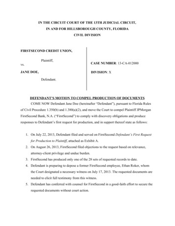
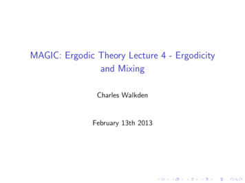
LECTURE 1: Electric Circuit Theory1.1 IntroductionTechnology is rapidly changing the way we do things; we now have computers in our homes,electronic control systems in our cars, cellular phones that can be used just about anywhere,robots that assemble products on production lines, and so on.A first step to understanding these technologies is electric circuit theory.Circuit theory provides you with the knowledge of basic principles that you need to understandthe behavior of electric and electronic devices, circuits, and systems.As an example, consider Figure 1.1 below, which shows a basic Radio receiver system.Its design is based on electrical, electronic, and magnetic circuit principles. For example,resistors, capacitors, transistors, and integrated circuits are used to control the voltages andcurrents that operate its motors and amplify the audio and video signals that are the heart of thesystem. A magnetic circuit, the power transformer, transforms the ac voltage from the 240-voltwall outlet voltage to the lower voltages required by the system.Figure 1.1: A Radio receiver is a familiar example of an electrical/electronic system.Its applications are all rooted in the principles of circuit theory.1 Page
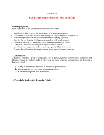
Figure 1.2: Some typical electronic components.1.2 Units associated with basic electrical quantitiesVery early units of measurement were based on the things easily available – the length of astride, the distance from the nose to the outstretched hand, the weight of a stone and the timelapse of one day. Over the years, new units were introduced and old ones modified. Differentbranches of science and engineering were working in isolation, using their own units, and theresult was an overwhelming variety of units.In all branches of science and engineering there is a need for a practical system of units whicheveryone can use. In 1960, the General Conference of Weights and Measures agreed to aninternational system called the Système International d’Unités ((abbreviated to SI units).SI unitsThe system of units used in engineering and science is the Systeme Internationale d’Unites(International system of units), usually abbreviated to SI units, It is based on the metric system.SI units are based upon a small number of fundamental units from which all other units may bederived. Table 1.1 describes some of the basic units we shall be using in our electrical studies.Like all metric systems, SI units have the advantage that prefixes representing various multiplesor submultiples may be used to increase or decrease the size of the unit by various powers of 10.Some of the more common prefixes and their symbols are shown in Table 1.2.2 Page
Table 1.1 Basic SI unitsQuantityAreaCurrent lMeasure ofLength x lengthElectric currentBasic UnitMetre squaredAmpereSymbolm2AEnergyAbility to do workJouleJForceThe effect on a bodyNewtonNFrequencyNumber of cyclesHertzHzLengthDistanceMetremMassAmount of materialKilogramKgMagnetic flux ΦMagnetic flux densityBPotential or pressureMagnetic energyNumber of lines ofmagnetic fluxVoltageWeberWbTeslaTVoltVPeriod TTime taken to completeone cycleSecondsPowerResistanceRate of doing workOpposition to current flowWattOhmWΩResistivityResistance of a samplepiece of materialOhm metreρTemperatureHotness or coldnessKelvinKTimeTimeSecondsWeightForce exerted by a massKilogramkgTable 2.2 Symbols and multiples for use with SI unitsPrefixMegaKiloHectoDecaDeciCentiMilliMicro3 PageSymbolMkhdadcmµMultiplication ,000,000100010010 10 100 1000 1,000,000NotesJoule is a verysmall unit3.6 x 106J 1kWhMains frequencyis 50 HzOne metrictonne 1000 kgThe 50 Hz mainssupply hasa period of 20msResistivity ofcopper is17.5x10-9Ωm0 C 273 K. Achange of1 K is the sameas 1 C60 s 1 min60 min 1 h1000 kg 1tonne
1.3 Standard symbols for electrical components1.4 Potential difference and resistance, and current.The drift of electrons within a conductor is known as an electric current, measured in amperesand given the symbol I.For a current to continue to flow, there must be a complete circuit for the electrons to movearound. If the circuit is broken by opening a switch, for example, the electron flow and thereforethe current will stop immediately.To cause a current to flow continuously around a circuit, a driving force is required, just as acirculating pump is required to drive water around a central heating system. This driving force isthe electromotive force (e.m.f.). Each time an electron passes through the source of e.m.f., moreenergy is provided to send it on its way around the circuit.4 Page
An e.m.f. is always associated with energy conversion, such as chemical to electrical in batteriesand mechanical to electrical in generators. The energy introduced into the circuit by the e.m.f. istransferred to the load terminals by the circuit conductors.The potential difference (p.d.) is the change in energy levels measured across the loadterminals. This is also called the volt drop or terminal voltage, since e.m.f. and p.d. are bothmeasured in volts. Resistance in every circuit offers some opposition to current flow, which wecall the circuit resistance, measured in ohms (symbol Ω), to commemorate the famous Germanphysicist Georg Simon Ohm, who was responsible for the analysis of electrical circuits. Asalready mentioned above, for a continuous current to flow between two points in a circuit apotential difference (p.d.) or voltage, V, is required between them; a complete conducting path isnecessary to and from the source of electrical energy. The unit of p.d. is the volt, V.Current flow, by convention, is considered as flowing from the positive terminal of the cell,around the circuit to the negative terminal.1.5 Basic electrical measuring instrumentsThe type of instrument to be purchased for general use in the electrical industries is a difficultchoice because there are so many different types on the market and every manufacturer’srepresentative is convinced that his company’s product is the best. However, most instrumentscan be broadly grouped under two general headings: those having analogue and those withdigital displays.Analogue meters or instrumentsAnalogue meters have a pointer moving across a calibrated scale. They are the only choice whena general trend or variation in value is to be observed. Hi-fi equipment often uses analoguedisplays to indicate how power levels vary with time, which is more informative than a specificvalue. Red or danger zones can be indicated on industrial instruments. The fuel gauge on a motorcar often indicates full, half-full or danger on an analogue display which is much moreinformative than an indication of the exact number of litres of petrol remaining in the tank5 Page
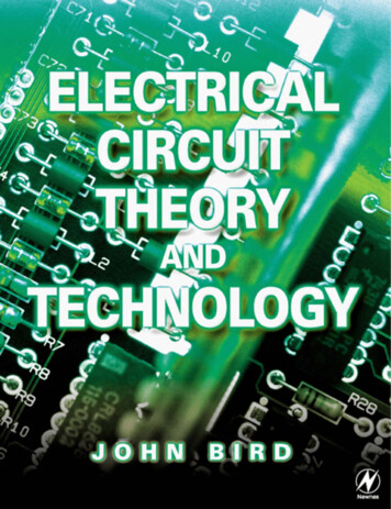
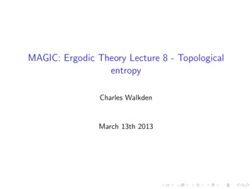
Figure 1.3 Analogue MultimeterThese meters are only accurate when used in the calibrated position – usually horizontally.Most meters using an analogue scale incorporate a mirror to eliminate parallax error. The usermust look straight at the pointer on the scale when taking readings and the correct position isindicated when the pointer image in the mirror is hidden behind the actual pointer. That is thepoint at which a reading should be taken from the appropriate scale of the instrument.Digital meters or instrumentsDigital meters provide the same functions as analogue meters but they display the indicatedvalue using a seven-segment LED to give a numerical value of the measurement. Modern digitalmeters use semiconductor technology to give the instrument a very high-input impedance,typically about 10 MΩ, and, therefore, they are ideal for testing most electrical or electroniccircuits.6 Page
Figure 1.4 Digital multimeter suitable for testing electrical and electronic circuitsThe choice between an analogue and a digital display is a difficult one and must be dictated byspecific circumstances. However, if you are an electrician or service engineer intending topurchase a new instrument, I think on balance that a good-quality digital multimeter such as thatshown in Fig. 1.4 would be best.Having no moving parts, digital meters tend to be more rugged and, having a very high-inputimpedance, they are ideally suited to testing all circuits that an electrician might work on in theirdaily work.An AmmeterAn ammeter is an instrument used to measure current and must be connected in series with thecircuit.7 Page
Figure 1.5Figure 1.5 shows an ammeter connected in series with the lamp to measure the current flowingthrough it.VoltmeterA voltmeter is an instrument used to measure potential difference and must be connected inparallel with the part of the circuit whose potential difference is required. To avoid a significantcurrent flowing through it a voltmeter must have a very high resistance.OhmmeterAn ohmmeter is an instrument for measuring resistance.A multimeter, or universal instrument, may be used to measure voltage, current and resistance.Figure 1.6The multimeterMultimeters are designed to measure voltage, current or resistance. Before taking measurementsthe appropriate volt, ampere or ohm scale should be selected. To avoid damaging the instrumentit is good practice first to switch to the highest value on a particular scale range. For example, ifthe 10A scale is first selected and a reading of 2.5 A is displayed, we then know that a more8 Page
appropriate scale would be the 3 A or 5 A range. This will give a more accurate reading whichmight be, say, 2.49 A. When the multimeter is used as an ammeter to measure current it must beconnected in series with the test circuit, as shown in Fig. 1.7(a). When used as a voltmeter themultimeter must be connected in parallel with the component, as shown in Fig. 1.7(b).When using a commercial multirange meter as an ohmmeter for testing electronic components,care must be exercised in identifying the positive terminal. The red terminal of the meter,identifying the positive input for testing voltage and current, usually becomes the negativeterminal when the meter is used as an ohmmeter because of the way the internal battery isconnected to the meter movement. Check the meter manufacturer’s handbook before using amultimeter to test electronic components.Figure 1.7 Using a multimeter (a) as an ammeter and (b) as a voltmeter1.6 Ohm’s lawIn 1826, Georg Simon Ohm published details of an experiment he had done to investigate therelationship between the current passing through and the potential difference between the ends ofa wire. As a result of this experiment he arrived at a law, now known as Ohm’s law, which saysthat the current passing through a conductor under constant temperature conditions isproportional to the potential difference across the conductor.9 Page
In essence, materials in general have a characteristic behavior of resisting the flow of electriccharge. This physical property, or ability to resist current, is known as resistance and isrepresented by the symbol R. The resistance of any material with a uniform cross-sectional areaA depends on A and its length L.𝑅 𝜌ℓ𝐴Where ρ is known as the resistivity of the material in ohmmeters. Good conductors, such ascopper and aluminum, have low resistivities, while insulators, such as mica and paper, have highresistivitiesOhm’s law states that the current I flowing in a circuit is directly proportional to the appliedvoltage V and inversely proportional to the resistance R, provided the temperature remainsconstant. Thus,𝐼 𝑉𝑉𝑜𝑟 𝑉 𝐼𝑅 𝑜𝑟 𝑅 𝑅𝐼The resistance R of an element denotes its ability to resist the flow of electric current; it ismeasured in ohms (Ω).ResistivityThe resistance or opposition to current flow varies for different materials, each having aparticular constant value. If we know the resistance of, say, 1 m of a material, then the resistanceof 5 m will be five times the resistance of 1 m. The resistivity (symbol ρ – the Greek letter ‘rho’)of a material is defined as the resistance of a sample of unit length and unit cross-section.Typical values are given in Table 1.3. Using the constants for a particular material we cancalculate the resistance of any length and thickness of that material from the equation𝑅 𝜌ℓ𝐴Table 1.3 gives the resistivity of silver as 16.4 10–9Ωm, which means that a sample of silver 1m long and 1 m in cross-section will have a resistance of 16.4 X 10⁻⁹Ω.10 P a g e
Table 1.3 Resistivity valuesMaterialResistivity (Ωm)Silver16.4 X 10-9Copper17.5 X 10-9Aluminium28.5 X10-9Brass75.0 X 10-9Iron100.0 X 10-9Example 1.1The current flowing through a resistor is 0.8 A when a potential difference of 20 V is applied.Determine the value of the resistance.From Ohm’s law, resistance R𝑉 20 200 25Ω𝐼 0.88Currents, voltages and resistances can often be very large or very small. Thus, multiples and submultiples of units are often used as shown in Table 1.2 above and below;11 P a g e
Example 1.2.Determine the p.d., which must be applied to a 2 k resistor in order that a current of 10 mA mayflow.𝑅𝑒𝑠𝑖𝑠𝑡𝑎𝑛𝑐𝑒 𝑅 2𝑘Ω 2 103 2000Ω𝐶𝑢𝑟𝑟𝑒𝑛𝑡 𝐼 10𝑚𝐴 10 10 3 𝐴 𝑜𝑟1010𝑜𝑟𝐴 0.01𝐴3101000𝐹𝑟𝑜𝑚 𝑂ℎ𝑚′ 𝑠𝑙𝑎𝑤, 𝑝𝑜𝑡𝑒𝑛𝑡𝑖𝑎𝑙 𝑑𝑖𝑓𝑓𝑒𝑟𝑒𝑛𝑐𝑒, 𝑉 𝐼𝑅 (0.01)(2000) 20𝑉Temperature coefficientThe resistance of most materials changes with temperature. In general, conductors increase theirresistance as the temperature increases and insulators decrease their resistance with a temperatureincrease. Therefore, an increase in temperature has a bad effect on the electrical properties of amaterial.Each material responds to temperature change in a different way, and scientists have calculatedconstants for each material which are called the temperature coefficient of resistance (symbol α –the Greek letter ‘alpha’).Table 1.4 gives some typical values.Table 1.4 Temperature Coefficient ValuesMaterialTemperature coefficient (Ω/Ω on0.00612 P a g e
Using the constants for a particular material and substituting values into the following formulaethe resistance of a material at different temperatures may be calculated. For a temperatureincrease from 0 C.𝑅𝑡 𝑅0 (1 𝛼𝑡)(Ω)WhereRt the resistance at the new temperature t CR0 the resistance at 0 Cα the temperature coefficient for the particular material.For a temperature increase between two intermediate temperatures above 0 C:𝑅1 (1 𝛼𝑡1 ) 𝑅2 (1 𝛼𝑡2 )WhereR1 the resistance at the original temperatureR2 the resistance at the final temperatureα the temperature coefficient for the particular material.If we take a 1Ω resistor of, say, copper, and raise its temperature by 1 C, the resistance willincrease to 1.004 Ω. This increase of 0.004 Ω is the temperature coefficient of the material.Example 1.3The field winding of a D.C. motor has a resistance of 100 Ω at 0 C. Determine the resistance ofthe coil at 20 C if the temperature coefficient is 0.004 Ω/Ω C.𝑅𝑡 𝑅0 (1 𝛼𝑡)(Ω)𝑅𝑡 100Ω(1 0.004 Ω Ω0 𝐶 200 𝐶)𝑅𝑡 100Ω(1 0.08)(Ω)𝑅𝑡 108Ω13 P a g e
Example 1.4The field winding of a shunt generator has a resistance of 150 Ω at an ambient temperatureof 20 C. After running for some time the mean temperature of the generator rises to 45 C.Calculate the resistance of the winding at the higher temperature if the temperaturecoefficient of resistance is 0.004 Ω/Ω C.𝑅1 (1 𝛼𝑡1 ) 𝑅2 (1 𝛼𝑡2 )150Ω (1 0.004 Ω Ω0 𝐶 200 𝐶)) 𝑅2(1 0.004 Ω Ω0 𝐶 450 𝐶))150Ω 1.08 𝑅21.08 𝑅2 150Ω 1.18 164Ω1.08It is clear from the last two sections that the resistance of a cable is affected by length, thickness,temperature and type of material. Since Ohm’s law tells us that current is inversely proportionalto resistance, these factors must also influence the current carrying capacity of a cable. The tablesof current ratings in Appendix 4 of the IEE Regulations contain correction factors so that currentratings may be accurately determined under defined installation conditions.1.7 Conductors and insulatorsAll matter is made up of atoms which arrange themselves in a regular framework within thematerial. The atom is made up of a central, positively charged nucleus, surrounded by negativelycharged electrons. The electrical properties of a material depend largely upon how tightly theseelectrons are bound to the central nucleus.A conductor is a material in which the electrons are loosely bound to the central nucleus andare, therefore, free to drift around the material at random from one atom to another as shown inFig. 1.8(a). A conductor is a material having a low resistance, which allows electric current toflow in it. All metals are conductors and some examples include copper, aluminium, brass,platinum, silver, gold and carbon.14 P a g e
An insulator is a material in which the outer electrons are tightly bound to the nucleus, so thatthere are no free electrons to move around the material. An insulator is a material having a highresistance, which does not allow electric current to flow in it. Some examples of insulatorsinclude plastic, rubber, glass, porcelain, air, paper, cork, mica, ceramics and certain oils.If a battery is attached to a conductor as shown in Fig. 1.8(b), the free electrons drift purposefullyin one direction only. The free electrons close to the positive plate of the battery are attracted toit since unlike charges attract, and the free electrons near the negative plate will be repelled fromit. For each electron entering the positive terminal of the battery, one will be ejected from thenegative terminal, so the number of electrons in the conductor remains constant.Figure 1.8 Atoms and electrons on a material.1.8 Electrical power and energyThe product of potential difference V and current I gives power, P in an electrical circuit. Theunit of power is the watt, W. Hence;𝑃 𝑉 𝐼 𝑤𝑎𝑡𝑡𝑠𝐹𝑟𝑜𝑚 𝑂ℎ𝑚’𝑠 𝑙𝑎𝑤, 𝑉 𝐼𝑅Substituting for V in equation above gives,𝑃 (𝐼𝑅) 𝐼𝑃 𝐼 2 𝑅 𝑤𝑎𝑡𝑡𝑠Also, from Ohm’s law,15 P a g e
𝐼 𝑉𝑅Substituting for I in equation above gives,𝑃 𝑉 𝑃 𝑉𝑅𝑉2𝑤𝑎𝑡𝑡𝑠𝑅There are thus three possible formulae, which may be used for calculating power.Exercise:A 100 W electric light bulb is connected to a 250 V supply. Determine (a) the current flowing inthe bulb, and (b) the resistance of the bulb.1. 9 Electrical energyElectrical energy power timeIf the power is measured in watts and the time in seconds then the unit of energy is watt-secondsor joules.If the power is measured in kilowatts and the time in hours then the unit of energy is kilowatthours, often called the ‘unit of electricity’. The ‘electricity meter’ in the home records thenumber of kilowatt-hours used and is thus an energy meter.Example 1.5A 12 V battery is connected across a load having a resistance of 40Ω. Determine the currentflowing in the load, the power consumed and the energy dissipated in 2 minutes.Current;𝐼 Power consumed;16 P a g e𝑉 12 0.3𝐴𝑅 40
𝑃 𝑉𝐼 (12)(0.3) 3.6𝑊𝐸𝑛𝑒𝑟𝑔𝑦 𝑑𝑖𝑠𝑠𝑖𝑝𝑎𝑡𝑒𝑑 𝑃𝑜𝑤𝑒𝑟 𝑇𝑖𝑚𝑒 (3.6 𝑊)(2 60𝑠) 432𝐽( 𝑆𝑖𝑛𝑐𝑒 1𝐽 1 𝑊𝑠)1.10. Kirchhoff’s laws(a) Current Law. At any junction in an electric circuit, the total current flowing towards thatjunction is equal to the total current flowing away from the junction, i.e.Σ𝐼 0𝐼1 𝐼2 𝐼3 𝐼4 𝐼5 𝑜𝑟 𝐼1 𝐼2 𝐼3 𝐼4 𝐼5 0Figure 1.9(b)Voltage Law. In any closed loop in a network, the algebraic sum of the voltage drops (i.e.products of current and resistance) taken around the loop is equal to the resultant e.m.f. acting inthat loop.Figure 1.1017 P a g e
The drift of electrons within a conductor is known as an electric current, measured in amperes and given the symbol I. For a current to continue to flow, there must be a complete circuit for the electrons to move around. If the circuit is broken by opening a switch, for example, the electron flow and ther