Transcription
Pipers Row Car Park, WolverhamptonQuantitative Study of the Causes of thePartial Collapse on 20th March 1997Jonathan G M WoodPhD MICE FIStructE CEngStructural Studies & Design LtdNorthbridge HouseChiddingfoldSurrey GU8 4UUjonathan@ss-design.demon.co.ukPipers Row Multi-Storey Car Park was built in 1965 and a 120 tonne section of the top floor collapsedduring the night of 20th March 1997. Initial reports identified some of the factors which contributed tothe initial punching shear failure which developed into a progressive collapse.This report has quantified the wider range of factors which, in combination, led to the collapse. It coversmore detailed investigation and testing of the construction, materials, degradation and repairs to thereinforced concrete Lift Slab structure. The sensitivity of the reactions, moments and shear stressdistributions to construction tolerances, cracking and the repair procedures have been evaluated, as havethe actual vehicle and thermal load effects. Comparisons of simplified design analysis with morerigorous analysis have been carried out, including ANSYS plate analysis of the whole slab and detailedDIANA non linear analysis of the stress concentrations around the Lift Slab shear head. The partialfactors on load and strength have been compared to the variability of load effects and punching shearstrength determined to BS8110 and on the basis of research studies. The reasons for the initial failureand its structural development into a progressive collapse have been considered.This report and the work it describes were funded by the Health and Safety Executive. Its contents,including any opinions and/or conclusions expressed, are those of the author alone and do notnecessarily reflect HSE policy.
ii
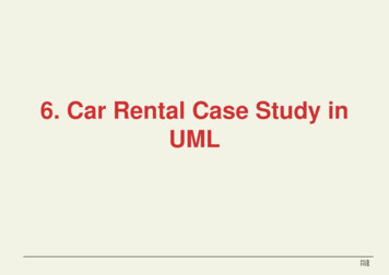
1 SUMMARYA 120 tonne section of the top floor of Pipers Row Multi-Storey Car Park collapsed at about 3am on20th March 1997. This report on the detailed quantitative investigation of the failure describes howaspects of design and construction reduced the factors of safety and inadequate inspection and partialrepair of developing deterioration led to a punching shear failure at one column which then spread.The lessons from this study have important implications for the safe design of flat slab structures and forthe appraisal, inspection, maintenance and repair of concrete structures of all types. It has highlightedthe need to identify in appraisal and inspection the risks from shortcomings of design and construction,and the effects of deterioration, before safety is compromised. It has identified some limitations in thecurrent approach in British Standards to the design and appraisal of structures which are inherently brittleand susceptible to progressive collapse, which become more serious as deterioration develops.1.1 DESIGN AND CONSTRUCTIONPipers Row Multi-Storey Car Park was built in 1965 by British Lift Slab Ltd (BLS) using the Lift Slabsystem of construction, in which concrete floor slabs, cast at ground level, are lifted up precast columnsand then supported on wedges engaging in welded angle shear collars cast into the slab. Theconfiguration of the area which failed is shown on Figure 1.3 - 1 and Figure 1.4 - 1.The design in 1964 was carried out to CP114 whose punching shear clauses give a poor, generallyoptimistic, prediction of strength. The basic calculations were reasonably carried out to CP114, but theholes adjacent to J2, tolerances on support wedges, and the effects of the detailing of the shear headswere ignored. The setting of the shear head support angle 22mm up into the slab reduced the strength ofthe slab and the 13mm mortar below provided uncertain fire protection even before premature corrosionspalled it off.The concrete was highly variable, some with low cement contents, poor mixing and compaction, so thatlocalised areas of concrete were substantially below the specified 20.5N/mm2 strength. This reduced theshear strength and made the concrete susceptible to premature deterioration. The reinforcement in theslab was set low leading to premature corrosion on the soffit. The high cover to the top steel, somewhatoffset by slight oversize on slab thickness, reduced the shear strength.Concrete density was lower than the design value and surfacing much thinner, which reduced deadloading from the design 6.2kN/m2 to 5.4kN/m2. The tolerances on setting the four wedges supporting theslab at each column usually resulted in all the reaction being taken on one wedge. Typically wedgescould be 5mm high or low relative to adjacent columns. Combined these misfits could have increasedthe effective shears around some columns by more than 40%.1
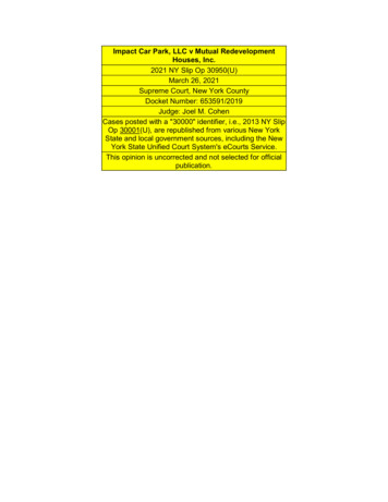
1.2 MAINTENANCE AND INSPECTION, 1988 TO 1995Severe local deterioration to concrete at the bottom of a ramp necessitated a substantial repair in 1987.After a punching shear progressive collapse during demolition of a similar Lift Slab car park at Coventryin 1988, a structural appraisal of Pipers Row for National Car Parks (NCP), the owner, concluded that ithad a “lesser margin of safety against a punching shear failure” than a 1988 design and that it wasimportant that this margin was “not reduced by significant deterioration of the materials”. Therecommended detailed survey and materials testing of the structure was not carried out.Signs of concrete deterioration and corrosion induced spalling progressively developed over the decadeprior to the collapse and some local patch repairs were carried out. Although further proposals for adetailed structural assessment and investigation of deterioration were made at intervals, no detailedsurvey and test programme was carried out prior to the collapse.1.3 INSPECTION AND REPAIR, 1996 TO 1997In 1996 parts of the deck slab which collapsed were patch repaired and re-waterproofed by Car DeckMaintenance (CDM) to stop leakage. There was an inspection by Harris & Sutherland (H&S), StructuralEngineers for NCP, but there was no proper investigation of deterioration, assessment of the structuraleffects of the deterioration and repair or specification for a structural repair. The repairs at H2 and J2were in the punching shear zones adjacent to the columns, see Figure 1.3.1. At both locations asubstantial area of concrete had become friable to below the level of the top reinforcement which wascorroding. If the drawings had been consulted, the sensitivity of the structure to punching shear with thedegradation and with the repair to below the top reinforcement, should have been apparent. The repairswere not taken out to the limits of deterioration leaving substantial areas of friable concrete withcorroding reinforcement unrepaired around H2. The area of deep degradation and reinforcementcorrosion around I2 was not identified.The repair material had properties well matched to the better concrete, but it was stiffer and strongerthan the weak concrete in the areas repaired. It was not well compacted around the reinforcement orwell bonded to the substrate concrete, which had not been cut out down to sound concrete. Althoughsome props were used during the repairs it is unclear if they were tightened to carry full dead load whilethe repair fully hardened.In January 1997 the slab was checked by CDM because of further leakage. A crack adjacent to J2 wasfound and considered potentially serious. In February NCP and H&S inspected the crack and localpropping at J2 was considered appropriate. A full inspection with materials testing and structuralassessment of the whole car park was recommended. The propping, detailed inspection and assessmenthad not started when the collapse occurred on 20th March, but the area of slab which collapsed and theslab below were coned off.2
thFigure 1.3 - 1 Plan of 4 floor slab at Pipers Row showing repaired areas3
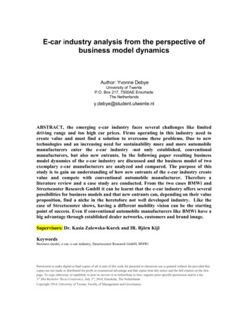
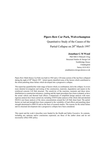
1.4 THE COLLAPSEA 120 tonne, 15m by 15m section of the top floor collapsed at about 3am on 20th March 1997 whenpunching shear failure at one column led to a progressive collapse as similar failures followed at eightadjacent columns. Fortunately the car park was empty, so there were no injuries, but the closure andsubsequent demolition of the whole 400 space car park caused substantial disruption to Wolverhampton.The initial punching shear failure in the concrete around the shear head could have occurred at H2 or I2,as at both the deterioration and/or repair substantially reduced the anchorage to the top steel essential forshear strength. Because of sensitivity to support wedge construction tolerances, H2 and I2 had similarindeterminate wide ranges of possible effective shear force from self weight at the time of collapse. TheLift Slab shear head and column connections remained intact.Which ever failed first, the other would have failed shortly after leaving the central area of slab saggingwith failures in flexure and increased shears to the edge columns. The sagging slab, acting as a tensionmembrane, pulled the edges inwards and then split along Line 2. Fortunately the lack of continuity in theslab and the reversal of moments towards G3 and H3 lead to the bottom steel peeling down out of theslab. This, together with the strength of the ramp between I3 and J3, prevented the further horizontalspread as I3 and J3 punched. The edge columns then failed in punching at H1 and I1 and G2 and J2. G1and J1 with bottom steel welded to the collar were pulled over, punching at J1 but not at G1. The pull ofJ1 towards I1 indicates that the central H2/I2 failure must have preceded the failure at J2. The foldingdown of the slab would have reduced the impact onto the undeteriorated 3rd Floor slab below, but it wasprobably fortuitous that this did not fail, setting off progressive failure down and across the wholestructure.1.5 THE DETERIORATIONThe design provided good falls for drainage, but the construction tolerances, deflection and creep of theslab created areas of ponding on the surface.Much of the surfacing and concrete surface layer of the failed slab was in good condition with minimalcarbonation (1 to 2mm). In some areas, including around H2, I2 and J2, waterproofing leakage andponding saturated the slab and frost damage developed to fissure and microcrack the concrete,particularly in local areas of high porosity and low strength. Salt crystallisation of urea, used for deicing for the previous decade, possibly also contributed to this. Some indications of ASR and ettringiteformation were noted in petrographic examination, but not at a level which would have significantlycontributed to the deterioration of the concrete. The friable degraded material was up to about 100mmdeep, well below the top reinforcement and a shallow, 5mm, intermediate layer separated it from theundeteriorated concrete below.Deep carbonation developed into the microcrack system and zones of high porosity, possibly aggravatedby CO2 released from the breakdown of urea. When microcracking reached the top reinforcement thecarbonation, not chlorides, initiated corrosion. Around I2 and around the repaired area at H2 corrosionindicates that degradation, sufficient to destroy most of the bond from steel to concrete, had developedfor most of the upper top layer (T1) of reinforcement and some of the lower (T2) layer.4
Figure 1.4 - 1 Collapsed 4th floor slab at Pipers Row Car Park, Wolverhampton on 25/3/975
1.6 ANALYSIS OF LOAD EFFECTSThe reactions and moments and resultant effective shear stresses at column locations have beenanalysed using BS8110 sub-frame, overall grillage and ANSYS plate idealisations. The sub-frameanalysis, with reduction in column reactions and moments from the moment redistribution permitted byBS8110, but not BS5400, gives shears 20% less than grillage and plate analysis for inner columns H2and I2, with 20% more to edge columns like J2. This could lead to a significant underestimate of themaximum load effects in assessment, which can be important for a brittle punching failure mode.The effective shear forces for a range of load cases, were determined using the elastic ANSYS plateanalysis. Table 1.6 - 1 summarises the major cases for H2, I2 and J2, relative to the self weight‘Reference Dead Load’ RefDL condition with perfect fit and uniform temperature.Table 1.6 - 1Load effects: effective shear Veff around columns as % of self weight RefDLVeff as % of self weight RefDLLoading, Self Weight H2I2J2Self Weight only RefDL100%100%100%Design Live loading (2.40kN/m2)143%143%145%.Medium vehicles in marked bays and aisles113%110%137%Differential temperatureFor night of collapse 20/3/97.March clear day102.5%102.0%104.2%106.2%98.6%.128.5%4 wedge vertical misfit 5mm124%115%116%All Load on one wedge 5mm153%142%143%The partial factor γf on load covers, with a good margin, the dead and vehicle loading and temperatureeffects. However the effects of construction tolerances on setting the slabs on wedges with the Lift Slabsystem are too large to be safely covered by the load factor and need explicit consideration in designand assessment.Creep, star cracking over inner columns and the deterioration would have altered the distribution ofreactions and moments between the columns and slab tending to reduce the effective shears at I2 and H2and increase those at J2 and other edge columns. With the limited propping during cutting out and repairthere would have been a reduction in effective shear force at H2 and J2 and a small increase at I2 ofabout 5%. Overall these effects would have only marginally influenced the risk of failure and fall withinthe margins which are covered by the partial factor γf on load effects.1.7 STRENGTHResearch on punching shear strength since the 1960s has shown the design method in CP114 to be oversimplified leading to an overestimate of strength for most structural configurations. It is clearlyinappropriate and inconsistent with IStructE recommendations Appraisal of Existing Strucures, to useCP114 rather than BS8110 for appraising older structures. BS8110:1985 (current prior to the collapse)and BS8110:1997,
Lift Slab shear head and column connections remained intact. Which ever failed first, the other would have failed shortly after leaving the central area of slab sagging with failures in flexure and increased shears to the edge columns. The sagging slab, acting as a tension membrane, pulled the edges inwards and then split along Line 2. Fortunately the lack of continuity in the