Transcription
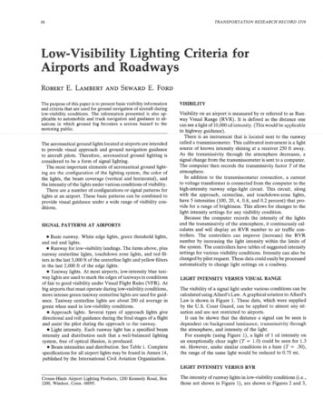
TRANSPORTATION RESEARCH RECORD 131668Low-Visibility Lighting Criteria forAirports and RoadwaysROBERTE.LAMBERT AND SEWARDE.FORDThe purpose of this paper is to present basic visibility informationand criteria that are used for ground navigation of aircraft duringlow-visibility conditions. The information presented is also applicable to automobile and truck navigation and guidance in situations in which ground fog becomes a serious hazard to themotoring public.The aeronautical ground lights located at airports are intendedto provide visual approach and ground navigation guidanceto aircraft pilots. Therefore, aeronautical ground lighting isconsidered to be a form of signal lighting.The most important elements of aeronautical ground lighting are the configuration of the lighting system, the color ofthe lights, the beam coverage (vertical and horizontal), andthe intensity of the lights under various conditions of visibility.There are a number of configurations or signal patterns forlights at an airport. These basic patterns can be combined toprovide visual guidance under a wide range of visibility conditions.SIGNAL PATTERNS AT AIRPORTS Basic runway. White edge lights, green threshold lights,and red end lights. Runway for low-visibility landings. The items above, plusrunway centerline lights, touchdown zone lights, and red filters in the last 3,000 ft of the centerline light and yellow filtersin the last 2,000 ft of the edge lights. Taxiway lights. At most airports, low-intensity blue taxiway lights are used to mark the edges of taxiways in conditionsof fair to good visibility under Visual Flight Rules (VFR). Atbig airports that must operate during low-visibility conditions,more intense green taxiway centerline lights are used for guidance. Taxiway centerline lights are about 200 cd average ingreen when used in low-visibility conditions. Approach lights. Several types of approach lights givedirectional and roll guidance during the final stages of a flightand assist the pilot luring the approach lo Lht: runway. Light intensity. Each runway light has a specified beamintensity and distribution such that a well-balanced lightingsystem, free of optical illusion, is produced. Beam intensities and distribution. See Table 1. Completespecifications for all airport lights may be found in Annex 14,published by the International Civil Aviation Organization.VISIBILITYVisibility on an airport is measured by or referred to as Runway Visual Range (RVR). It is defined as the distance onecan see a light of 10,000 cd intensity. (This would be applicableto highway guidance).There is an instrument that is located next to the runwaycalled a transmissometer. This calibrated instrument is a lightsource of known intensity shining at a receiver 250 ft away.As the transmissivity through the atmosphere decreases, asignal change from the transmissometer is sent to a computer.The computer then records the transmissivity factor T of theatmosphere.In addition to the transmissometer connection, a currentto voltage transformer is connected from the computer to thehigh-intensity runway edge-light circuit. This circuit, alongwith the approach, centerline, and touchdown-zone lights,have 5 intensities (100, 20, 4, 0.8, and 0.2 percent) that provide for a range of brightness. This allows for changes to thelight intensity settings for any visibility condition.Because the computer records the intensity of the lightsand the transmissivity of the atmosphere, it continuously calculates and will display an RVR number to air traffic controllers. The controllers can improve (increase) the RVRnumber by increasing the light intensity within the limits ofthe system. The controllers have tables of suggested intensitysettings for various visibility conditions. Intensity can also bechanged by pilot request. These data could easily be processedautomatically to change light settings on a roadway.LIGHT INTENSITY VERSUS VISUAL RANGEThe visibility of a signal light under various conditions can becalculated using Allard's Law. A graphical solution to Allard'sLaw is shown in Figure 1. These data, which were suppliedby the U.S. Coast Guard, can be applied to almost any situation and are not restricted to airports.It can be shown that the distance a signal can be seen is lt:pt:n lenl on background luminanct:, lransmissivily throughthe atmosphere, and intensity of the light.For example (using Figure 1), a light of 1 cd intensity onan exceptionally clear night (T 1.0) could be seen for 1.3mi. However, under similar conditions in a haze (T .30),the range of the same light would be reduced to 0. 75 mi.LIGHT INTENSITY VERSUS RVRCrouse-Hinds Airport Lighting Products, 1200 Kennedy Road, Box1200, Windsor, Conn. 06095.The intensity of runway lights in low-visibility conditions (i.e.,those not shown in Figure 1), are shown in Figures 2 and 3,
TABLE 1 LIGHT CHARACTERISTICS FOR CATEGORIES I, II, AND III PRECISION APPROACH RUNWAYSMinimum Beam CoverageMain BeamLightColourH111.pp oach2centre line andvlOT.Hv5?.Hv7Minimum averageintensity in specified coloursCd x 10 3Angular SettingsLimits of AverageIntensity Ratio Elevation Toe-in(degrees) (degrees)34568910White2011281330 17201.5-2 max .Red1410231233 16512110-2B-5. 5crossbarsApproach side row0.5-126.5 - 5.5ThresholdGreen119151218 17101.0 - 1.55,53. 5Threshold wing barGreen1410231233 16101.0 - 1.55. 52Touchdown zonelfuite107141217 1750,5-15. 54Runway centre line (15 m)White/Red10914171 7 202.50.25-0.54. 50Red124.5151018 132.50.25-0.52. 50White117151218 171.03. 53.5P.unway endRunway edge (45 m rum1ay)10BACKGROUND LUMINANCECANDLES/M 2CLEAR MOONLIGHTTWLIGHTOVERCAST DAYCLEAR DAY.033.3003000· 1 - 1-- O1- -;)()10. .:;'(I ,,.·, - . : :-.THIN FOGo 1-, ,,10 HAZEzo- ·-:1LIGHT HAZE"',·- 1--·-.-1- ·- -- T. ·1 · . , --"'--'--'-'CUIU1t .L.J LJ.1.JJJ.l LJ JUJ.lllJL---L.LLl.ILWIL-.L.LJUJJJ.lJ'--J .LJ.LlllJl J J .1.llJWJ.IOIQ(). 67- NONE100tpooI.,.IIPOO10,0004040040006. 7 - MINOR67 CONSIDERABLEBACKGROUND LIGHTINGILLUMINATION AT THE EYEIN SEA-MILE-CANDLESALLARD'S LAW NOMOGRANA graphical solution of Allard's Law: I E IllumanceD2With a fixed transmissivity T and background illumination E, the graph relatesrange D to effective in tens i ty I. The three intensity scales indicate levelsof background lighting.FIGURE 1 Graphical solution of Allard's Law.E
td NI § t" t' 1ozsc: "'':- 900t"E §!"'H .0 ("") gif lu 'Ct' 1t' 1000Cl).::;::Ht"At' 170020 0CANDELASFIGURE 2 Visibility distance versus light source candle power at night.2000FIGURE 3 Visibility distance versus light source candle power during the day.3SG1 0 9 10000
Lambert and Ford71and Tables 2 and 3. Data were supplied by the Port Authorityof New York and New Jersey. It must be remembered thatthe definition of RVR is based on a high-intensity light of10,000 ed.In the airport environment, visibility conditions are definedas follows: Category II. An instrument runway served by ILS andvisual aids intended for operations down to a 30-m (100-ft)decision height and down to an RVR of 400 m (1,300 ft). Category IIIA. This category is the same as Category IIexcept RVR is 200 m (650 ft), with no minimum decisionheight and visual aids used during the final phase of landing. Category IIIB. RVR is 50 m (160 ft), with no minimumdecision height and no visual aids used for landing. VFR. VFR apply when meteorological visibility (outsidecontrolled airspace) is greater than 1 mi during the day and3 mi at night. Cloud data are not included here because theyare not applicable to the discussion. Category I. An instrument runway served by InstrumentLanding System (ILS) and visual aids intended for operationsdown to a 60-m (200-ft) decision height and down to an RVRof 800 m (2,600 ft).In referring to Figure 2 and Table 2, it can be seen that anintensity setting at Step 4 (2,000 cd on the edge lights spacedat 200 ft) and (1,000 cd on the runway touchdown zone lightsspaced at 100 ft) provides 800 ft of visibility at 900 RVR. AtStep 5 (10,000 cd on the Edge Light and 5,000 on the Touchdown Zone Lights) the visibility is increased to 900 ft. InTABLE 2 VISUAL RANGE UNDER LOW RVR CONDITIONSAT NIGHTINTENSITYOF SOURCE(CANDELAS IVISUAL RANGE OF SOURCE 2147182300121159198236312387l, 0001311732162583424253 '00014018623227836946010' 000150200250300400500100' R IS THE VISUAL RANGE OFTHRESHOLD IS 2 MILE CANDELAS.A 10,000CANDELA SOURCE. THE ILLUMINANCETABLE 3 VISUAL RANGE UNDER LOW RVR CONDITIONSDURING THE DAYINTENSITYSOURCE(CANDELAS IVISUAL RANGE OF SOURCE 3300105138169200259316l , 000120158196233305376J '00013417822126435043410. 000150200250300400500100' R IS THE VISUAL RANGE OF A 10,000THRESHOLD IS 1,000 MILE CANDELA.CANDELA LIGHT.THE ILLUMINANCE
TRANSPORTATION RESEARCH RECORD 131672other words, 5 times more light is needed to obtain another100 ft of usable visibility. Similar examples can be given fordaytime conditions from Figure 3 and Table 3.of various ages, optimum operating speeds, and whether othercolors or patterns would improve the Afton Mountain installation. Recent accidents on highways during low-visibilityconditions, when no lighting was available, indicate the potential for this kind of system.AIRPORT DATA APPLICABLE TO ROADWAYSThe low-visibility systems used at airports are applicable toroadways under conditions of heavy fog when the transmissivity of the atmosphere falls below T 0.05.Such a condition takes place in Virginia on Afton Mountainon Interstate 64. The Virginia Highway Department, aftertrying many types and combinations of signs and reflectors,installed roadway inpavement (airport) lights to provide guidance for the motoring public under sudden and severe lowvisibility conditions when clouds would suddenly cover themountain ;mn nrive:rs wonln he:rnme: inst;mtly lost in the fog.The Virginia Highway Department, in conjunction with theVirginia Highway Research Council, determined that inpavement runway lights were the only practical solution to this difficult and extremely dangerous highway guidance problem.A system of lights using a modified runway touchdownzone light and a detection system to determine fog densitywas installed on a 6.25-mi section of divided highway. Thelights were located 200 ft apart on both sides of the road ina manner similar to runway edge lights. These inpavementlights have been in service for 10 years, and the results havebeen more than favorable.The use of aeronautical ground lights for low-visibility roadway application is a subject that requires additional study todetermine the effects of these navigational lights on driversOTHER POTENTIAL HIGHWAY APPLICATIONSAnother attribute of runway lights is that they are placed ina position in which the pilot or motorist is normally looking.For instance, inset red lights could be placed within a railroadcrossing area instead of overhead. Even someone with pooreyesight or someone whose mind is on another subject couldnot help but see the red signal. In many applications, theintensity of inpavement lights for roadway applications couldbe on the order of 200 cd (similar to airport taxiway centerlinelights) if the spacing were reduced to 25 ft. If spacing weregreater, then a higher mtens1ty would be reqmred.SUMMARYIn summary, Allard's Law is applicable to all signal visibilityconditions. Special attention must be given to intensity, spacing, color, and patterns to provide the visual guidance neededfor various conditions of vehicle operation by people 16 yearsof age and older.With ever-increasing traffic, the problem of guidance inlow-visibility conditions must be addressed if highway accidents involving scores of vehicles are to be avoided.
Crouse-Hinds Airport Lighting Products, 1200 Kennedy Road, Box 1200, Windsor, Conn. 06095. VISIBILITY Visibility on an airport is measured by or referred to as Run way Visual Range (RVR). It is defined as the distance one can see a light of 10,000 cd i