Transcription
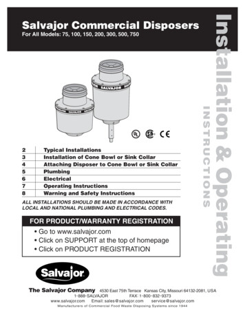
For All Models: 75, 100, 150, 200, 300, 500, 750Typical InstallationsInstallation of Cone Bowl or Sink CollarAttaching Disposer to Cone Bowl or Sink CollarPlumbingElectricalOperating InstructionsWarning and Safety InstructionsALL INSTALLATIONS SHOULD BE MADE IN ACCORDANCE WITHLOCAL AND NATIONAL PLUMBING AND ELECTRICAL CODES.FOR PRODUCT/WARRANTY REGISTRATION Go to www.salvajor.com Click on SUPPORT at the top of homepage Click on PRODUCT REGISTRATIONThe Salvajor CompanyINSTRUCTIONS2345678Installation & OperatingSalvajor Commercial Disposers4530 East 75th Terrace Kansas City, Missouri 64132-2081, USA1- 888- SALVAJORFAX: 1 - 800 - 832 - 9373www.salvajor.comEmail: s of Commercial Food Waste Disposing Systems since 1944
Typical Installations1/2"VACUUMBREAKERPLUMBINGCONE OR SINKWATERINLETINCOMING POWER(P)(PP)Models 300 through750 furnished withsingle support leg.OPTIONALREMOTESTART/STOP2" DRAIN (models 75-200)2" OR 3" DRAIN (models 300-750)CONTROLWITH (P) OR (PP)1/2" VALVE(NF)INCOMING WATER3/4" PLUMBINGREDUCED TO NOID VALVEWITH FLOW CONTROL1/2" VALVE(NF)INCOMING WATER3/4" PLUMBINGREDUCED TO 1/2"WATERINLETCONE2" DRAIN(models 75-200)INCOMING POWERCONTROL2" OR 3" DRAIN(models 300-750)1/2"OPTIONALSHORT TOPHOUSINGPLUMBINGVACUUMBREAKERSOLENOID VALVEWITH FLOW CONTROL1/2" VALVE(NF)SINKINCOMING WATER3/4" PLUMBINGREDUCED TO 1/2"WATERINLET2" DRAIN(models 75-200)2" OR 3" DRAIN(models 300-750)CONTROLOPTIONALSHORT LEG2INCOMING POWER
Installation of CONE BOWL or SINK COLLARCONE ASSEMBLY3 1 2" Sink Collar #701. Cut a hole in the counter top of theappropriate table cutout dimensionslisted below.1. Apply caulking compound around the sinkhole (TOP SIDE).ApplicationCutout Size12" Cone Bowl12 7 8" Diameter15" Cone Bowl15 8" Diameter18" Cone Bowl18 7 8" Diameter2. Insert the stainless steel adaptor in thesink hole.3. Place the gasket over the stainless steeladaptor (UNDER SINK).74. Place the hex metal washer over thestainless steel adaptor, up against thegasket.2. Place the large open end of the cone bowlagainst the counter top and weld the flange.Weld all the way around and then buffsmooth for a watertight, sanitary installation.5. Place the sink collar with O-ring insertedover the stainless steel adaptor, up againstthe hex metal washer.6. Slip the spring steel snap ring over thebottom of the stainless steel adaptor andslide up until it snaps into the groove in thestainless steel adaptor.SINK COLLARS:6 1 2" Sink Collar #651. If necessary, cut a 6 5/8" DIAMETER holein the center of the bottom of the sink.7. Screw the hex head bolts out of the sinkcollar and up against the hex metal washertight enough to firmly set the assembly.2. Place the adaptor against the underside ofthe sink and weld all the way around. Buffsmooth for a watertight, sanitary installation.8. The disposer rubber adaptor fits over thesink collar and bands to the sink collar.#65 SINK COLLARSINK#70 SINK COLLARLARGE RUBBERSTOPPER (LRS)SINKRUBBER STOPPER(5088)S.S. SINKADAPTOR(S5028)3 1/2" - 4"SINKOPENING6 5/8"SINK OPENINGWELD INSINK COLLAR(65)HEX METALWASHER(S5028F)GASKET(S5028G)S.S. HEX HEADBOLTS (997031)O-RING(568237)SPRING STEEL SNAPRING RETAINER(S5028LS)3SINK COLLAR(70C)
Attaching Disposer to CONE BOWL or SINK COLLAR1. Carefully remove the top housingassembly by removing the eight bolts makingsure not to damage the center gasket.2. Apply lubricant to the rubber collar ontop housing and the beaded collar on coneor sink.3. Slip the top housing assembly up onto thebeaded collar and tighten the clamp so thetop housing assembly can not be pulleddown over the bead. If attaching disposer toSalvajor ScrapMaster or TroughVeyor, useshort top housing and cut out rubber baffleson hycar adaptor to reduce bridging of foodwaste.4. Measure distance from the bottom of thetop housing to floor.5. Turn the disposer on its side and installthe leg support (optional on Models 75-200,standard on Models 300-750) on the bottomof the disposer and adjust the leg extensionso the disposer will stand approximately 1/2"below the bottom of the top housing.Measure distancebetween floor andbottom of tophousingLOCKINGTABS6. Carefully balancing the disposer on theleg support, walk it under the top housing,aligning the ears on the shredder ring withthe locking tabs of the top housing.7. Slide the center gasket into place. Insertthe top housing bolts through holes in the tophousing and into the disposer body housing.As you the tighten bolts, the disposer will pullup securely to the top housing.GASKET8. Extend the leg extension securely on thefloor, and tighten set screws.NOTE: It is important that the leg fit tightly between thedisposer and the floor.STOP!If you have any questions about this installationcall 1-888-SALVAJOR for installation advice.4
PlumbingDRAIN PIPINGWATER SUPPLY1. Before installing the Salvajor disposer,the waste line should be properly cleanedout to the connecting main sewer.6. Connect COLD WATER ONLY to disposer.Recommended Cold Water Supply2. Use as few elbows, tees and bends aspossible when making connections.Models 75, 100, 150, 2005GPMModels 300, 500, 7508GPMWater volume can be controlled by a properlyrated flow control valve or hand operatedvalve.3. All horizontal drain lines should have aminimum fall of 1/4" per foot.4. A 3" diameter pipe is recommended forSalvajor disposers models 300 thru 750.A 2" adapter is supplied for existing 2" drains.Models 75 thru 200 require a 2” drain.(Nos. 7-9 below for NEW INSTALLATIONS ONLY!)7. Plumb 3/4" IPS line and reduce to 1/2" atthe hand valve. Install the factory-suppliedsolenoid valve with built-in flow control.IMPORTANT!It is imperative to have a proper downward pitch from thedisposer outlet to the main sewer line to assure propergravity flow. Improper drain line installation can result indrain backups.8. From the solenoid, plumb 1/2" IPS lineabove the flood plane of the table and installthe factory supplied vacuum breaker to localcode.9. Plumb 1/2" IPS line from the vacuumbreaker to either cone bowl, sink or tophousing inlet on the disposer. If connectingto cone or sink, use 1 2" water inlet suppliedby the factory.5. Do not connect into a grease trap,interceptor or drum trap.NOTE: Pressure regulators should be installed in areaswhere pressure exceeds the recommended maximum of80 psi.NOTE: CONNECT COLD WATER ONLY TO DISPOSER.Tempered water from pre-rinse or Salvajor scrappingsystem is acceptable, but only in conjunction with anindependent, continuous cold water supply.TYPICAL SINK LAYOUTTYPICAL CONE LAYOUTMAKE ALL PLUMBING CONNECTIONS IN ACCORDANCEWITH LOCAL AND NATIONAL PLUMBING CODES.5
ElectricalGENERAL INSTRUCTIONSTEST PROCEDUREDual voltage disposers are shipped from the factory NOTconnected for a specific voltage. Please refer to the wiringdiagrams on the disposer junction box cover. Whenconnecting single phase disposers to a reversing control,refer to the diagram supplied with the control. Salvajordisposer cutting elements are designed to operate ineither direction.1. Check to be sure the disposer cutting teeth are free offoreign objects.Use water tight conduit and fittings to make connections.4. If disposer fails to operate:A. Turn off power.B. Check wiring connections.C. Determine if the RESET button has tripped.Reset by hand only.2. Turn the disposer on and determine that the cuttingelements rotate freely and that water flows automatically.3. Check the mounting assembly and plumbing connectionsfor leaks.Caution: Be careful not to pinch wires when replacing junctionbox cover.For new installations, an approved control will need to bemounted in the dish table with an optional bracket. Powerwill have to be run to a solenoid for incoming water.DANGER: If disposer stops, DO NOT look for the cause until thestarting control is turned OFF and the power is turned OFF.Consult Operating Instructions.NOTE: The RESET button is located on the bottom of the disposer.Full Load Amps( 2 HP )Model200Model200( 3 4 HP )ModelModel75 75115 Volts208 Volts230 Volts208 Volts230 Volts460 Volts1 Phase1 Phase1 Phase3 Phase3 Phase3 Phase115 Volts208 Volts230 Volts208 Volts230 Volts460 Volts17.8 Amps9.9 Amps9.0 Amps4.2 Amps4.0 Amps2.1 Amps1 Phase1 Phase1 Phase3 Phase3 Phase3 Phase( 3 HP )ModelModel300300( 1 HP )Model100Model100115 Volts208 Volts230 Volts208 Volts230 Volts460 Volts1 Phase1 Phase1 Phase3 Phase3 Phase3 Phase208 Volts230 Volts460 Volts18.6 Amps10.2 Amps9.3 Amps4.9 Amps4.5 Amps2.3 Amps1 Phase1 Phase1 Phase3 Phase3 Phase3 Phase3 Phase3 Phase3 Phase8.8 Amps8.0 Amps4.0 Amps( 5 HP )Model500Model500208 Volts230 Volts460 Volts( 1 1 2 HP )Model150150Model115 Volts208 Volts230 Volts208 Volts230 Volts460 Volts24.0 Amps12.1 Amps12.0 Amps6.6 Amps6.0 Amps3.0 Amps22.9 Amps11.8 Amps11.6 Amps6.2 Amps5.6 Amps2.6 Amps3 Phase3 Phase3 Phase13.8 Amps12.5 Amps6.3 Amps( 7 1 2 HP )ModelModel750750208 Volts230 Volts460 Volts3 Phase3 Phase3 Phase19.8 Amps18.0 Amps9.0 AmpsWIRING DIAGRAMSSINGLE PHASE 115 VOLT4L 15J2183L 2SINGLE PHASE 208 VOLT54L 1J283541L 2SINGLE PHASE 230 VOLTL 1J28313 PHASE 208/230 VOLT3 PHASE 460 VOLT101112101112456456789789123123L 1L 2L 3L 1L 2L 3L 2USE CONTROL PANEL WIRING DIAGRAM when using Salvajor Controls(Models ARSS, ARSS-LD, ARSS-2 or MRSS) (Single Phase Only)TO REVERSE ROTATION: Interchange #5 & #8 (Single Phase Only)MAKE ALL INSTALLATIONS IN ACCORDANCEWITH LOCAL AND NATIONAL ELECTRICAL CODES.6
Salvajor Commercial DisposerOPERATING INSTRUCTIONS123Push the START button on the control panel to begin operation.Before you start feeding food waste into the disposer, make surethat a steady stream of water is flowing into the unit. Don’t startfeeding garbage into the disposer until the unit is startedand the water is running.Feed garbage into the disposer in a steady continuousflow. Don’t overload the disposer with excess amountsof garbage and water. The disposer will consume foodwaste faster when you feed it steadily.Always keep your hands away from a disposer when it is operating.Don’t stop the disposer with garbage in it. Let it run for approximately3 minutes to clear itself of all ground waste. This will help to maintaina clean and odor-free unit and to avoid drain line clogs.Push the STOP button on the control panel to stopoperation. To prevent accidents, make sure thedisposer is shut off before you leave it unattended.TROUBLESHOOTINGWARNING! Disconnect the power to the disposer before servicing.PROBLEMPOSSIBLE CAUSESOLUTIONThe disposer will not startand water does not flow.The disposer will not startbut water flows.No incoming power.Check breaker and disconnect.Turn power on.Turn the disposer control off and press the reset button on the disposer.If the disposer was running, allow the unit to cool for 3-5 minutes beforepressing the reset button. Never strike the reset button with an object.The disposer motoroverload is tripped.The disposer is jammed.Turn the power off to the disposer and complete the following steps:1. Insert the dejamming prong through the sink (or cone) opening.Place the prong over the center raised bars found on the top ofthe disposers revolving rotor.2. Twist the dejamming bar back and forth to free the jam.The revolving rotor should turn freely when the jam is released.3. Remove all foreign material that caused the stoppage.4. Allow the disposer to cool for 3-5 minutes after it stops running.Press the reset button to reset the motor overload protector.Never strike the reset button with an object.5. If the disposer remains inoperative after following these steps,contact the nearest Salvajor Factory Authorized Service Center, orthe factory direct. You may obtain the telephone number of theService Center nearest you by calling 1-888-SALVAJOR.The disposer motor stopswhile grinding, but watercontinues to flow.The disposer is jammed.See: The disposer is jammed, above.The disposer motoroverload is tripped.See: The disposer motor overload is tripped, above.The water flowscontinuously before thecontrols are turned on.Incorrect water solenoidinstallation.Reinstall so that the arrow on the solenoid is pointing in the direction ofthe water flow.Motor overload tripsfrequently.Disposer is overloadedwith food waste.Do not overload the disposer with excessive amounts of food waste.Hot water used in lieu ofcold.Reconnect with cold water.7
Warning!HOPPERS, SINKS & CONE BOWLSRisk of injury to persons from hazardous moving parts.Serious injury possible if not properly installed with aUL-listed hopper, sink or cone.All replacement cones/ hoppers, sinks and chutes used withSalvajor disposers should be of equal construction per theabove standard.All Salvajor cone bowls and chutes are designed and builtper UL Standard 430 Section 7 Enclosures, subsection 7.1.2(Exception 1), 7.1.3, and 7.1.6 using 16 Gauge nominalstainless steel sheet.The following Salvajor cones manufactured as of 11-01- 96comply with UL Standard 430 Section 28.3.1 (Exception 1)and 28.3.2:P/N CB-12, CB-15, CB-18.TYPICAL SALVAJOR DISPOSER TO CONE BOWL / DEEP SINK INSTALLATION5 3/8"MIN.CONE BOWL/DEEP SINKINTERNALTHROATOPENING6 1/2" IDDISPOSERTOP HOUSINGNOTE: Above Installation Per UL Standard 430 Height Requirements.CONTROLSPer UL 430, install using a UL-listed electrical control panel.The following Salvajor electrical control panels manufactured as of 11-01-96comply with UL Standard 430 Section 28.3.1 (Exception 1) and 28.3.2:model numbers MSS, MSS-LD, MRSS, MRSS-LD, ARSS-2, ARSS, and ARSS-LD.SAFETY INSTRUCTIONS1Read all the instructions before using the disposer.2Keep safety baffle over throat of disposer.3Always keep your hands away from disposer when it is running.4Push STOP button on control panel and shut off electrical power to the panel before attemptingto clear a jam.5When attempting to clear a jam in a disposer use a Salvajor dejamming tool or a long woodenobject to reverse rotation6To reduce risk or injury by materials that may be expelled from the unit, do not put the followingitems into a disposer:A. Clam or oyster shellsB. Drain cleaner or corrosive detergentsC. Glass, china or plasticsD. Metal such as bottle caps, tin or aluminum cans, etc.REMEMBER! Always keep hands away from a disposer when it is running.8Printed in USAForm No. II-DISP-9-BH
(models 75-200) 2" or 3" drain (models 300-750) control incoming power solenoid valve with flow control vacuum breaker water inlet optional pre-rinse cone incoming water 3/4" plumbing reduced to 1/2" 1/2" valve (nf) 1/2" plumbing 2" drain (models 75-200) 2" or 3" drain (models 300-750) typica