Transcription
IMPORTANT UPDATE OCTOBER 8, 2014TECHNICAL INSTRUCTIONSFORSAFETY RECALL D0BSUB HARNESS (FILTER) INSTALLATION2003 – 2004 MODEL YEAR COROLLAUPDATED OCTOBER 8, 2014Updated 10/8/14 Flow chart updated. Health check now required along with a list of DTC’s to determine Airbag Sensorreplacement and the addition of technical skill lever requirements.Updated 5/13/13 The inspection has been updated to clarify the request for DTCs (if present) for MAC part release(SECTION VI)Updated 5/1/13 The inspection has been updated to request that DTCs (if present) are recorded for MAC part release(SECTION VI)Updated 4/15/13 The airbag sensor assembly part numbers have been updated (SECTION III)Updated 4/2/13 The inspection process at STEPS 1 & 2 have been updated to clarify the inspection process (SECTION VI)All dealership associates involved in the recall process are required to successfully complete E-Learning courseSC13A. To ensure that all vehicles have the repair performed correctly; technicians performing this recall repairare required to currently hold at least one of the following certifications levels: Toyota Expert (Electrical) Master Master Diagnostic Technicians
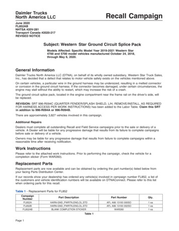
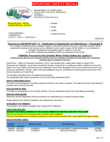
I.OPERATION FLOW CHARTVerify Vehicle Eligibility1. Check the VIN range.2. Check the TIS Vehicle InquirySystem.Not CoveredNo further action required.CoveredCheck for airbag related DTCsYesReplace SRS ECUNoInstall the sub harness.Campaign complete, return the vehicleto the customer.This campaign only covers theinstallation of the sub harness and ifneeded the airbag sensor assembly.No other components in the SRSsystem are covered by this campaign.II. IDENTIFICATION OF AFFECTED VEHICLESA. INVOLVED VEHICLESNOTE: Check the TIS Vehicle Inquiry System to confirm the VIN is involved in this Safety Recall, and that thecampaign has not already been completed prior to dealer shipment or by another dealer. TMS warranty will not reimburse dealers for repairs conducted on vehicles that are not affected or werecompleted by another dealer.III. PREPARATIONA. PARTSAll vehicles require the installation of this kit.Part NumberPart Description04002-66112Airbag Harness Kit*Quantity1*The kit above includes the following parts. Airbag sub harness1 Water guard sheet1 Cable tie4**Only 2 cable ties are needed for the repair, 2 extra ties are alsoprovided as supplements.The Airbag Sensor should only be replaced after preforming a Health Check as indicated in STEP 1.Parts will be placed on recovery and subject to claim debit for inappropriate replacement.Part Number89170-0219189170-02201Part DescriptionAirbag Sensor Assembly (Without Side Airbag)Airbag Sensor Assembly (With Side Airbag)Quantity112
B. TOOLS & EQUIPMENT Standard hand toolsMolding remover set Torque wrenchTape measure TechstreamVinyl tapeIV. BACKGROUNDThe Electronic Control Module (ECM) for the Supplemental Restraint System (SRS) in these vehicles could have beenmanufactured with integrated circuits that are susceptible to internal short circuiting when exposed to certain electricalnoise from various vehicle electrical components. If internal short circuiting occurs, the front airbag(s) and/or seat beltpre-tensioners could inadvertently deploy. An airbag that deploys inadvertently can, under some circumstances,increase the risk of minor injury and the possibility of a crash.V. COMPONENTSVI. WORK PROCEDURE1. PREFORM A HEALTH CHECKThis campaign only covers the installation of the sub harness and if needed the airbag sensorassembly (SRS ECU). No other components in the SRS system are covered by this campaign.a)Using Techstream, perform a health check to confirm if there are any airbag related DTCs present in the system(Both current or history). If any of the DTC’s stored in the vehicles SRS system match the list below, proceedto Step 2.NOTES: Ensure that the Techstream software is 9.2 or higher. On the “connect to vehicle” screen, enter the VIN number to ensure that the vehicle information isuploaded to TIS. Record the SRS DTCs as they are used to confirm the vehicles final state after repair and aid in anyadditional dicussions needed with the customer. If the there is no communication between the SRS ECU and Techstream DTCs cannot be retrieved, inthis scenario state, continue to Step 2 and replace the SRS ECU called out in step 10.3
DTC No.Detection ItemDTC No.Detection ItemB0100Short in D squib circuitB0131Open in P/T squib (RH) circuitB0101Open in D squib circuitB0132Short in P/T squib (RH) circuit (to ground)B0102Short in D squib circuit (to ground)B0133Short in P/T squib (RH) circuit (to B )B0103Short in D squib circuit (to B )B0135Short in P/T squib (LH) circuitB0105Short in P squib circuitB0136Open in P/T squib (LH) circuitB0106Open in P squib circuitB0137Short in P/T squib (LH) circuit (to ground)B0107Short in P squib circuit (to ground)B0138Short in P/T squib (LH) circuit (to B )B0108Short in P squib circuit (to B )B1100Airbag sensor assembly malfunctionB0110Short in side squib (RH) circuitB1180Short in D squib (2nd step) circuitB0111Open in side squib (RH) circuitB1181Open in D squib (2nd step) circuitB0112Short in side squib (RH) circuit (to ground)B1182Short in D squib (2nd step) circuit(to ground)B0113Short in side squib (RH) circuit (to B )B1183Short in D squib (2nd step) circuit (to B )B0115Short in side squib (LH) circuitB1185Short in P squib (2nd step) circuitB0116Open in side squib (LH) circuitB1186Open in P squib (2nd step) circuitB0117Short in side squib (LH) circuit (to ground)B1187Short in P squib (2nd step) circuit(to ground)B0118Short in side squib (LH) circuit (to B )B1188Short in P squib (2nd step) circuit (to B )B0130Short in P/T squib (RH) circuitb) If no DTC’s are present continue to STEP 2 but skip Step 10This campaign only covers the installation of the sub harness and if needed the airbag sensorassembly. No other components in the SRS system are covered by this campaign.2. DISCONNECT THE NEGATIVE BATTERY TERMINAL Wait at least 90 seconds after disconnecting the cable from the negative battery terminal to preventairbag and seat belt pre-tensioner deployment.Follow all precautions as outlined on TIS before servicing the SRS system.3. SET THE PARKING BRAKE4. SLIDE THE DRIVER AND PASSENGER SEAT TO THE REARMOST POSITION4
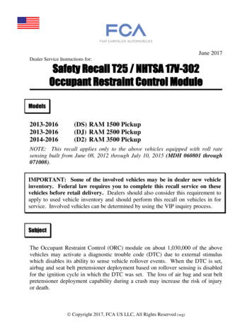
5. PERFORM THE FOLLOWINGa)b)Remove the shift lock release button cover (auto trans only).Move the shift lever to the N position.c)d)Remove the parking brake hole cover sub-assembly.Remove the shift lever knob cover sub-assembly (manual trans only).e)f)Remove the shifting hole cover sub-assembly (manual trans only).Remove the console panel upper (auto trans only).g)Remove the console box carpet.h)i)Disconnect the auxiliary power outlet harness(s).Remove the screws then the console box.5
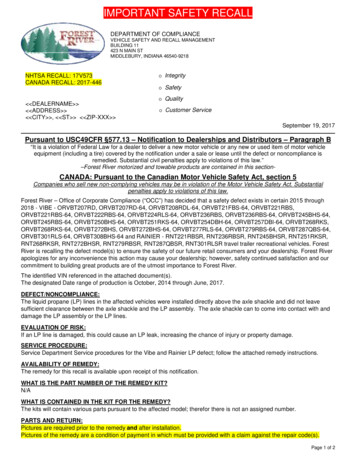
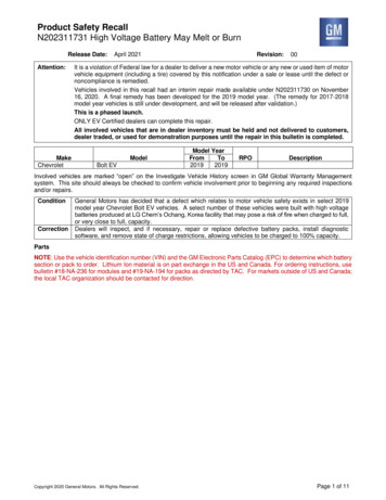
6. REMOVE THE FLOOR CARPET LHa)Unfasten the Velcro fastener.b)Remove the clip and pull back the floor carpet.NOTE: Wear protective gloves. Remove the floor carpet enough to gain access to theairbag sensor.7. REMOVE THE FLOOR CARPET RHa)Remove the 2 clips and pull back the floor carpet.NOTE: Wear protective gloves. Remove the floor carpet enough to gain access to theairbag sensor.8. REMOVE AIR DUCT REAR No. 3a)Pull the upper portion of the duct rearward to disengage the 2upper claws.b)Pull the bottom portion of the duct upward to disengage the 4claws and remove the duct.9. DISCONNECT THE AIRBAG SENSOR CONNECTORSa)Disconnect the 3 connectors.Only replace the airbag sensor assembly if DTC’s are found as descriped in STEP 1. If no DTC’s wheredetected, skip this step and proceed to STEP 11.10. REPLACE THE AIRBAG SENSOR ASSEMBLYa)Remove the 3 bolts and the airbag sensor assembly.b)Install a NEW airbag sensor assembly, then continue toSTEP 12.Torque: 13ft. lbf (17.5N m)6
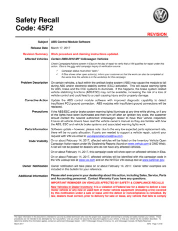
All vehicles require the installation of the sub harness regardless if the airbag ECU is being repalced or not.11. PREPARE THE SUB HARNESSa)To prevent noise, secure the 3 female connectors togetherwith vinyl tape.To prevent the tape from interfering with theconnectors, DO NOT wrap the tape around the frontportion of the connectors.12. POSITION THE SUB HARNESSa)Fold back the plastic sheet on the top of the airbag sensor.NOTE: DO NOT remove the plastic sheet as it will cause the sensor label to peel off.b)Place the NEW sub harness on top of the airbag sensor.13. CONNECT THE SUB HARNESSa)Connect the 3 NEW connectors to the airbag sensor.7
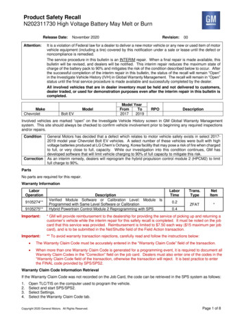
b)Connect the 3 vehicle-side connectors to the NEW subharness.14. INSTALL THE WATER GUARD SHEETa)Position the water guard sheet over the airbag sensor and sub harness.b)Position the sheet so that the edge protrudes 1.2 to 2.0 in.(30 to 50 mm) past the back side of the airbag sensor.8
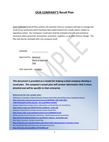
c)d)Adhere the tape on the sheet to the right side of the airbagsensor approximately 0.6 to 1.0 in. (15 to 25 mm) above thebottom end of the sensor.Confirm the sheet has been positioned correctly.e)Pass a cable tie through the space under the airbag sensor, then connect another cable tie.NOTE: Only 2 cable ties are needed for the repair, 2 extra ties are also provided as supplements. If it is difficult to pass the cable underneath the airbag sensor, loosen the 3 bolts that fasten the sensor.Torque: 13ft. lbf (17.5N m)f)Join the cable ties and secure the sub harness, water guard, and airbag sensor together.g)Cut any excess lengh from the cable tie.9
The water guard sheet is critical to prevent water from the air conditionerfrom dripping on theairbag sensor, confirm it is positioned and adhered correctly.DO NOT bind the oxygen sensor harness/connector with the cable ties.If the cable tie or sheet is affixed incorrectly, the sub harness may not be fixed properly.15. REINSTALL AIR DUCT REAR No. 3a)Engage the 4 claws on the lower portion of the duct.b)Engage the 2 claws on the upper portion of the duct.16. REINSTALL THE FLOOR CARPET RHa)Reposition the carpet and engage the 2 clipsConfirm the floor carpet is secure and the clip is not damaged. Failure to secure the carpet could resultin pedal interference.17. REINSTALL THE FLOOR CARPET LHa)Reposition the carpet and engage the clip.b)Fasten the Velcro fastener.10
18. PERFORM THE FOLLOWINGa)b)Install the console box and install the screws.Connect the auxiliary power outlet harness(s).c)d)Install the console box carpet.Install the console panel upper (auto trans only).e)Install the shift lever knob cover sub-assembly (manual trans only).f)g)Install the shifting hole cover sub-assembly (manual trans only).Install the parking brake hole cover sub-assembly.h)Install the shift lock release button cover (auto trans only).19. RECONNECT THE NEGATIVE BATTERY TERMINAL20. CHECK THE AIRBAG WARNING INDICATORa)Check that the warning indicator illuminates when the ignitionis switched on.b)Confirm that the warning light will go off after about 6 secondshave elapsed after IG on. After the 6 second illumination of the warningindicator, if the indicator goes off then back on orremains on, check for DTCs and confirm the subharness was installed correctly.Consult with the customer to determine if theywould like to diagnose/repair any remainingconcerns.11
21. RESTORE VEHICLE SETTINGSa)b) Restore any memory settings.Return the seats to their original positions. VERIFY REPAIR QUALITY Confirm any DTCs prior to beginning this repairRead all precautions as outlined on TIS before servicing the SRS systemConfirm ALL harness connectors are connected securelyConfirm the water guard sheet is secured and positioned correctlyConfirm the sub harness is secured correctly on top of the airbag sensorConfirm there are no DTCs when the repair is completeIf you have any questions regarding this update, please contact your area representative.VII. APPENDIXA. CAMPAIGN DESIGNATION DECODERC0Year Campaign is Launched Repair Phase8 20089 2009A 2010B 2011C 2012D 2013E 2014F 2015Etc.0 Remedy1 Prelim/Interim2 Prelim/Interim forPhase 2 Vehicles(Remedy not yetavailable) “1 or 2” willchange to “0” when theRemedy is availableTCurrent Campaign Letterfor this year1st Campaign A2nd Campaign BEtc.B. CAMPAIGN PARTS DISPOSALAs required by Federal Regulations, please make sure all campaign parts (original parts) removed from thevehicle are disposed of in a manner in which they will not be reused, unless requested for parts recoveryreturn.12
2003 – 2004 MODEL YEAR COROLLA UPDATED OCTOBER 8, 2014 Updated 10/8/14 . Toyota Expert (Electrical) . Open in side squib (RH) circuit B1181 Open in D squib (2nd step) circuit B0112 . Short in side squib (RH) circui