Transcription
INL/EXT-08-14981Modified MTS MRB500Catalyst PerformanceTestGlen R. LonghurstRobert J. PawelkoOctober 2008The INL is a U.S. Department of Energy National Laboratoryoperated by Battelle Energy Alliance
INL/EXT-08-14981Modified MTS MRB500 Catalyst Performance TestGlen R. LonghurstRobert J. PawelkoOctober 2008Idaho National LaboratoryFuels and Materials Performance DepartmentIdaho Falls, Idaho 83415http://www.inl.govPrepared for theU.S. Department of EnergyOffice of National Nuclear Security AdministrationUnder DOE Idaho Operations OfficeContract DE-AC07-05ID14517
DISCLAIMERThis information was prepared as an account of work sponsored by anagency of the U.S. Government. Neither the U.S. Government nor anyagency thereof, nor any of their employees, makes any warranty, expressedor implied, or assumes any legal liability or responsibility for the accuracy,completeness, or usefulness, of any information, apparatus, product, orprocess disclosed, or represents that its use would not infringe privatelyowned rights. References herein to any specific commercial product,process, or service by trade name, trade mark, manufacturer, or otherwise,does not necessarily constitute or imply its endorsement, recommendation,or favoring by the U.S. Government or any agency thereof. The views andopinions of authors expressed herein do not necessarily state or reflectthose of the U.S. Government or any agency thereof.1
ii
ABSTRACTAn experiment was conducted to determine if the oxygen supply in a CuO catalyst consideredfor use in the TMIST-2 irradiation test would be sufficient to convert all the hydrogen isotopescoming from the irradiation test to water. A mixture of 2% H2 in Ar was supplied to a modifiedMRB 500 stack monitor from Mound Techology Solutions, Miamisburg, OH. It was found thatthe catalyst could convert 3.75E-03 moles of H2 before losing its effectiveness. Conversion wasfound to begin at a catalyst temperature of about 220 C and to be fully effective at about 300 C.iii
iv
CONTENTSBACKGROUND . 1EXPERIMENT . 2Apparatus. 2Experiments. 4DISCUSSION . 6CONCLUSION. 7REFERENCE. 7FIGURESFigure 1. Elements of the MTS MRB 500 in its standard configuration. 1Figure 2. Configuration of modified MRB 500 stack monitor. . 2Figure 3. Experiment configuration for evaluating catalyst performance. . 3Figure 4. Test data for initial mass-2 visibility determination. 4Figure 5. Catalyst performance with temperature. 5Figure 6. Catalyst exhaustion. 6v
vi
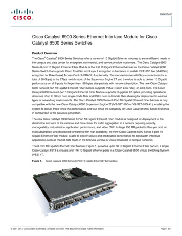
BACKGROUNDThe TMIST-2 experiment at the Idaho National Laboratory will be seeking to capture very smallquantities of tritium emerging from an experiment in an inert gas stream. Because of the smallquantities involved, the most reliable means of measurement is scintillation counting of tritiumcollected in bubbler vials. A standard means of making similar measurements for tritiumaccountancy in ventilating air stacks is by means of a discriminating bubbler array. One of theseis manufactured by Mound Technical Solutions of Miamisburg, Ohio. The standardconfiguration of their MRB 500 is shown in Figure 1.Figure 1. Elements of the MTS MRB 500 in its standard configuration.These instruments pass the gas stream to be analyzed through a set of 3 bubbler vials in whichwater soluble forms of tritium are captured. The gas then goes through a Pd sponge catalyst bedwhere elemental hydrogen isotopes are oxidized. The gas is then passed to the second bank ofbubblers where the newly soluble tritium is captured. This allows differentiation as to tritiumform in the gas stream.For the TMIST-2 experiment, a mixture of He and Ne carrying small amounts of tritium will bepushed through the system from pressurized gas bottles. There is no need for the vacuum pump,the mass flow controller and related equipment. With the entire system at atmospheric pressureor above, the ambient air inlet valve would not be functional, so it too may be omitted.In the conventional application, the carrier gas is air in which there is typically 19% oxygen foroxidizing the tritium in the catalyst bed. For the TMIST-2 application, the carrier gas will be amixture of He and Ne with no oxygen. Therefore, it was decided that the Pd sponge catalyst bedcould be replace with CuO, which could furnish the oxygen for the oxidizing reaction, at least fora time. That leaves the instrument configuration as shown in Figure 2.1
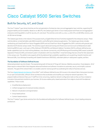
Figure 2. Configuration of modified MRB 500 stack monitor.There are two concerns with this selection of means for capturing the tritium. One is whether ornot the CuO catalyst can supply enough oxygen to perform its intended function over the life ofthe experiment. The second is whether the small quantity of tritium involved will get lost in thecatalyst housing and other structures or come through for an accurate measure of the tritium inthe gas stream. The second concern is not admissible of testing without actually using tritium inthe small quantities anticipated for the TMIST-2 application. Further, these instruments havebeen used for many years and have not demonstrated the propensity for holdup of the tritium inthe catalyst bed. The presence of the water from the first bubbler array no doubt contributes tominimizing or eliminating any such hold up. Therefore, there is every reason to believe that holdup will be at most a transient delay in the measurement of the tritium coming from theexperiment to the bubblers. The other concern, oxygen sufficiency, is the reason for the presentexperiment.EXPERIMENTTo determine the extent of oxygen availability of this CuO catalyst, hydrogen bearing argon wasflowed over the catalyst bed at a known rate, passing through a mass spectrometer. By observingthe time at which the catalytic reaction stopped, we get a measure of the oxidizing capacity of thespecific configuration of this instrument.ApparatusThe configuration of the experiment is shown in Figure 3. The Ar supply was a size K bottle ofresearch grade Ar. After trying several different bottles of D2 – Ar mixtures, none of which hadsignals sufficiently visible on the mass spectrometer because of the low D2 concentrations, weultimately used a small bottle of Ar – 2% H2 as the hydrogen supply.2
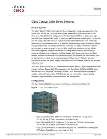
MFC-1V4Research Grade ArLoanedMRB 500 withCuO CatalystV1CalibratedBuretteV2MFC-2Ar – 2% H2V3MassSpectrometerFigure 3. Experiment configuration for evaluating catalyst performance.Mass flow controllers (MFCs) were Teledyne Hastings HFC-304 units that had been calibratedfor N2 at 30 psig inlet pressure. One was supposed to be full scale at 5 sccm but actually gaveabout 10.5 sccm. The other was supposed to be 20 sccm at full scale but actually gave almost 60sccm. The MFCs were controlled using a Teledyne Hastings THPS 400 four-channel control unit.We were working with Ar at about 20 psig inlet pressure because the available pressure reliefvalve, V4, required for safety, opened at about 26 psig. Because we had no confidence in theflow calibration of the MFCs, we used a calibrated burette in which a soap film meniscus travelsupward through a calibrated volume in measured times to determine flow rates very accurately.This was used to find the flow rate commanded to the supposed 20-sccm MFC that gave thesame 10.5-sccm gas flow measured through the supposed 5-sccm MFC.The mass spectrometer consisted of a SRD CIS 200 quadropole evacuated by a BOC EdwardsEXT 70H 24V turbomolecular pump backed by a BOC Edwards XDS 5 scroll pump. Samplingwas done through a Varian M1515106 leak valve adjusted to provide gas pressure in thequadropole of about 5E-06 torr. The incoming gas flow passed through a 1/8-inch tube directlyagainst the leak valve inlet port. Control and data display were provided by SRS RGA VersionRelease 3.004 software on a Dell Optiplex GX110 PC. It was operated in RGA mode at 70 Vionizing potential at 50 µA emission current and 90 V focusing voltage. Even though thequadropole housing had been baked under vacuum and operated with no gas flow for severaldays, the signal was very noisy. It was difficult but possible to distinguish the mass-2 peak fromnoise at the 2% concentration.The valve configuration shown in Figure 3 allowed us to run gas with or without the H2component either through the MRB 500 or around it. Most of the tubing in the system was 3163
SS, but some lines were ¼-inch PVC. We experimented with line type, replacing PVC with SS inan attempt to reduce system noise, but we saw no significant difference. Connections weremostly Swagelok compression fittings with some VCR and some NPT with Teflon tape on gasbottle regulators.ExperimentsAfter two days of working with the system and finally arriving at a combination of gascomposition and settings that seemed to work, the first test was to demonstrate that the mass-2signal was clearly present and visible. This was done by alternately flowing gas with and withoutthe H2 present at the 10.5-sccm flow rate through the bypass line, going around the MRB 500.Some results are shown in Figure 4.Mass 2Mass 183.0E-10Pure Ar throughbypassH2 throughMRB 500H2 throughbypass2.5E-10Ion Current (A)2.0E-101.5E-101.0E-105.0E-110.0E 000102030405060Time (min)Figure 4. Test data for initial mass-2 visibility determination.These data begin with H2 flowing through the bypass. The ion current was about 1.8E-10 A. Atapproximately 2 minutes into the scan, the gas flow was changed to include only Ar at nearly thesame flow rate. There was a short lag while the changing gas composition reached the massspectrometer. Then, the ion current fell in a time commensurate with some mixing taking placein the gas lines and some H2 trickling in from dead spaces in the gas lines not on the direct flowpath. After about 15 minutes, the signal had reached the system background level.At 20 minutes into the scan, the H2 was readmitted to the gas stream. The reverse process tookplace in the mass-2 signal. The apparent variations in the mass-18 signal during this time werecorrelated generally oscillations in pressure in the quadropole. They suggest that the mass flows4
through the 2 MFCs were not quite balanced. Only one was open at a time, MFC-1 when onlypure Ar was wanted and MFC-2 when the Ar – 2% H2 was flowed. Subsequent measurementsthrough the calibrated burette showed the flow through MFC-1 was 8.46 sccm while that throughMFC-2 was 7.06 sccm.At 33 minutes into the scan, the gas with H2 was redirected through the MRB 500. The mass-2signal immediately fell but then recovered as the volume of the catalyst bed and the gas lines inthat part of the experiment became filled with the H2 mixture. It is noteworthy that there was noobserved increase of mass 18 during that time. The gas coming out of the second bubbler shouldhave been saturated with water vapor at 20.8 C (2.8% of the local atmospheric pressure), a littlegreater fraction than the H2. Even if there was a delay while tube wall surfaces became saturatedwith adsorbed water, it should have risen eventually. We did not see any evidence of the mass 18signal changing in the experiment.With H2 bearing gas flowing through the MRB 500, we then started on a temperature ramp toevaluate the temperature at which the CuO became effective in catalyzing the oxidation of the H2.These results are shown in Figure E-10250200Temperature (C)Ion Current (A)2.0E-101.0E-101501005.0E-11500.0E 000204060801000120Time (min)Figure 5. Catalyst performance with temperature.The temperature ramp started at about 103 C (we had kept the catalyst at just over 100 C to tryto keep it dry). Over the course of 80 minutes, the temperature increased linearly to 475 C.Considering the time lag for transport from the catalyst to the mass spectrometer, it appears thecatalysis began at about 220 C, consistent with results from other experiments performed for thisproject using CuO catalyst.1 By 340 C, all of the H2 was being removed.5
The next test was to see how long the oxygen on the catalyst would last. This was done bysimply leaving the experiment in the configuration just described overnight. Figure 6 shows dNormalized Ion Current2.5E-102.0E-101.5E-101.0E-105.0E-110.0E 0002468101214Time (hr)Figure 6. Catalyst exhaustion.After 5.4 hours in this scan (6.67 hours total) with 2% H2 in Ar flowing at 10.5 sccm at atemperature greater than 280 C, the catalyst began to lose efficiency. Until that time, it had beenvery effective in removing H2 from the gas stream. The total number of moles of H2 that passedthrough the catalyst before it began losing effectiveness was6.67 hr u60 min 10.5 scc0.02 moleuu1 hr1 min2.24 u 10 4 scc3.75 u 10 3 mole .DISCUSSIONIn the TMIST-2 experiment, there will be 6 modified MRB 500 equivalents. Four of these willbe used to recover tritium in very low amounts from He-Ne mixtures. An upper bound estimateon the amount of tritium each may see is 1E-05 moles. Clearly, the capacity demonstrated aboveshould be well sufficient to meet that need unless there is vastly more H than T in the system,which is highly unlikely. One other MRB 500 equivalent system, unit 5, will be used as ascavenger to process the flows from the first 4, one at a time, while the first 4 units are havingtheir vials changed. Again, unit 5 should be easily able to handle the demand for oxygen placed6
on it. The final MRB 500 equivalent will be used to scavenge any tritium that may make itthrough a pair of Zr-Fe getter beds. An anticipated upper bound on the load it may see is2 u 10 3 Cim3u1 mole5.8 u 104Ciu1 u 10 -5 m 3u 8.64 u 10 6 sec1 sec2.8 u 10 -6 mole .An ion chamber between the two getter beds will notify operators if the concentration thereexceeds the 2 mCi/m3 value used in this calculation.After the catalyst bed tested in this experiment had stopped converting the H2 to water, it wasregenerated by passing room air over it at 475 C for 15 minutes. Following that process andrestoring the H2-carrying gas flow through the system, the mass-2 signal in the massspectrometer was at background level, similar to that shown in Figures 4 and 5.This test was not able to demonstrate that the water coming into the reaction from the bubblercould be counted on to undergo isotopic exchange and thus capture the tritium. It is probable thatthe isotopic exchange effect would be highly effective at capturing the small amount of tritium inthe water vapor while effectively passing H2 on in its place. That cannot be determined in thisexperiment without actually using tritium. Available time and laboratory resources do not admitof testing that process.CONCLUSIONThe MRB 500 stack monitor units modified with a CuO catalyst bed in a manner similar to theone we received for testing should be very satisfactory for use in the TMIST-2 experiment. If forany reason there is a need to regenerate the CuO, it may be simply done by passing air over thehot bed.REFERENCE1. G. R. Longhurst, February 2008, “TMIST-2 Transport Test,” INL/EXT-08-13791, IdahoNational Laboratory, Idaho Falls, ID 83415.7
The INL is a U.S. Department of Energy National Laboratory operated by Battelle Energy Alliance