Transcription
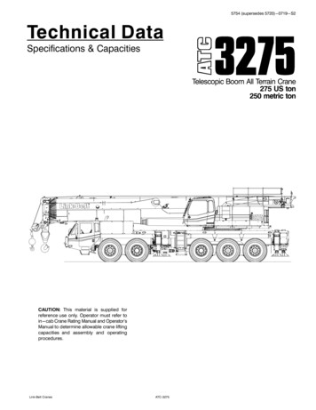
5754 (supersedes 5720)-0719-S2Technical DataSpecifications & CapacitiesTelescopic Boom All Terrain Crane275 US ton250 metric tonRCAUTION: This material is supplied forreference use only. Operator must refer toin-cab Crane Rating Manual and Operator'sManual to determine allowable crane liftingcapacities and assembly and operatingprocedures.Link‐Belt CranesATC‐32751
5754 (supersedes 5720)-0719-S2ATC‐3275Link‐Belt Cranes
5754 (supersedes 5720)-0719-S2Table Of ContentsBoom, Attachments, and Upper Structure . . . . . . . . . . . . . . . . . . . . . . . . . . . . . . . . . . . . . . . . . . . . . . . . . . . .Boom . . . . . . . . . . . . . . . . . . . . . . . . . . . . . . . . . . . . . . . . . . . . . . . . . . . . . . . . . . . . . . . . . . . . . . . . . . . . . . . . . . . .Boom . . . . . . . . . . . . . . . . . . . . . . . . . . . . . . . . . . . . . . . . . . . . . . . . . . . . . . . . . . . . . . . . . . . . . . . . . . . . . . . . . . .Boom Wear Pads . . . . . . . . . . . . . . . . . . . . . . . . . . . . . . . . . . . . . . . . . . . . . . . . . . . . . . . . . . . . . . . . . . . . . . . . .Boom Head . . . . . . . . . . . . . . . . . . . . . . . . . . . . . . . . . . . . . . . . . . . . . . . . . . . . . . . . . . . . . . . . . . . . . . . . . . . . .Boom Elevation . . . . . . . . . . . . . . . . . . . . . . . . . . . . . . . . . . . . . . . . . . . . . . . . . . . . . . . . . . . . . . . . . . . . . . . . . .Auxiliary Lifting Sheave - Optional . . . . . . . . . . . . . . . . . . . . . . . . . . . . . . . . . . . . . . . . . . . . . . . . . . . . . . . . .Heavy Duty Lifting Sheave Package - Optional . . . . . . . . . . . . . . . . . . . . . . . . . . . . . . . . . . . . . . . . . . . . . .Hook Blocks and Balls - Optional . . . . . . . . . . . . . . . . . . . . . . . . . . . . . . . . . . . . . . . . . . . . . . . . . . . . . . . . . .Fly - Optional . . . . . . . . . . . . . . . . . . . . . . . . . . . . . . . . . . . . . . . . . . . . . . . . . . . . . . . . . . . . . . . . . . . . . . . . . . .Fly Extensions - Optional . . . . . . . . . . . . . . . . . . . . . . . . . . . . . . . . . . . . . . . . . . . . . . . . . . . . . . . . . . . . . . . . .Upper Operator's Cab and Controls . . . . . . . . . . . . . . . . . . . . . . . . . . . . . . . . . . . . . . . . . . . . . . . . . . . . . . . . . .Swing . . . . . . . . . . . . . . . . . . . . . . . . . . . . . . . . . . . . . . . . . . . . . . . . . . . . . . . . . . . . . . . . . . . . . . . . . . . . . . . . . . . .Central Lubrication System . . . . . . . . . . . . . . . . . . . . . . . . . . . . . . . . . . . . . . . . . . . . . . . . . . . . . . . . . . . . . . . . .Electrical . . . . . . . . . . . . . . . . . . . . . . . . . . . . . . . . . . . . . . . . . . . . . . . . . . . . . . . . . . . . . . . . . . . . . . . . . . . . . . . . .Hydraulic System . . . . . . . . . . . . . . . . . . . . . . . . . . . . . . . . . . . . . . . . . . . . . . . . . . . . . . . . . . . . . . . . . . . . . . . . . .Pump Drive . . . . . . . . . . . . . . . . . . . . . . . . . . . . . . . . . . . . . . . . . . . . . . . . . . . . . . . . . . . . . . . . . . . . . . . . . . . . . . .Fuel Tank . . . . . . . . . . . . . . . . . . . . . . . . . . . . . . . . . . . . . . . . . . . . . . . . . . . . . . . . . . . . . . . . . . . . . . . . . . . . . . . . .Engine . . . . . . . . . . . . . . . . . . . . . . . . . . . . . . . . . . . . . . . . . . . . . . . . . . . . . . . . . . . . . . . . . . . . . . . . . . . . . . . . . . .Load Hoist System . . . . . . . . . . . . . . . . . . . . . . . . . . . . . . . . . . . . . . . . . . . . . . . . . . . . . . . . . . . . . . . . . . . . . . . . .Load Hoist Performance . . . . . . . . . . . . . . . . . . . . . . . . . . . . . . . . . . . . . . . . . . . . . . . . . . . . . . . . . . . . . . . . . . .2M Main (Front) and Optional Auxiliary (Rear) Winches . . . . . . . . . . . . . . . . . . . . . . . . . . . . . . . . . . . . . . .Counterweight . . . . . . . . . . . . . . . . . . . . . . . . . . . . . . . . . . . . . . . . . . . . . . . . . . . . . . . . . . . . . . . . . . . . . . . . . . . .Carrier . . . . . . . . . . . . . . . . . . . . . . . . . . . . . . . . . . . . . . . . . . . . . . . . . . . . . . . . . . . . . . . . . . . . . . . . . . . . . . . . . . . .General . . . . . . . . . . . . . . . . . . . . . . . . . . . . . . . . . . . . . . . . . . . . . . . . . . . . . . . . . . . . . . . . . . . . . . . . . . . . . . . . . . .Outriggers . . . . . . . . . . . . . . . . . . . . . . . . . . . . . . . . . . . . . . . . . . . . . . . . . . . . . . . . . . . . . . . . . . . . . . . . . . . . . . . .Steering and Axles . . . . . . . . . . . . . . . . . . . . . . . . . . . . . . . . . . . . . . . . . . . . . . . . . . . . . . . . . . . . . . . . . . . . . . . . .Suspension . . . . . . . . . . . . . . . . . . . . . . . . . . . . . . . . . . . . . . . . . . . . . . . . . . . . . . . . . . . . . . . . . . . . . . . . . . . . . . .Ground Control Outrigger/Suspension Controls . . . . . . . . . . . . . . . . . . . . . . . . . . . . . . . . . . . . . . . . . . . . . . .Tires and Wheels . . . . . . . . . . . . . . . . . . . . . . . . . . . . . . . . . . . . . . . . . . . . . . . . . . . . . . . . . . . . . . . . . . . . . . . . . .Brakes . . . . . . . . . . . . . . . . . . . . . . . . . . . . . . . . . . . . . . . . . . . . . . . . . . . . . . . . . . . . . . . . . . . . . . . . . . . . . . . . . . .Central Lubrication System . . . . . . . . . . . . . . . . . . . . . . . . . . . . . . . . . . . . . . . . . . . . . . . . . . . . . . . . . . . . . . . . .Electrical . . . . . . . . . . . . . . . . . . . . . . . . . . . . . . . . . . . . . . . . . . . . . . . . . . . . . . . . . . . . . . . . . . . . . . . . . . . . . . . . .Transmission . . . . . . . . . . . . . . . . . . . . . . . . . . . . . . . . . . . . . . . . . . . . . . . . . . . . . . . . . . . . . . . . . . . . . . . . . . . . . .Fuel Tank . . . . . . . . . . . . . . . . . . . . . . . . . . . . . . . . . . . . . . . . . . . . . . . . . . . . . . . . . . . . . . . . . . . . . . . . . . . . . . . . .Engine . . . . . . . . . . . . . . . . . . . . . . . . . . . . . . . . . . . . . . . . . . . . . . . . . . . . . . . . . . . . . . . . . . . . . . . . . . . . . . . . . . .Hydraulic System . . . . . . . . . . . . . . . . . . . . . . . . . . . . . . . . . . . . . . . . . . . . . . . . . . . . . . . . . . . . . . . . . . . . . . . . . .Pump Drive . . . . . . . . . . . . . . . . . . . . . . . . . . . . . . . . . . . . . . . . . . . . . . . . . . . . . . . . . . . . . . . . . . . . . . . . . . . . . . .Carrier Speeds and Gradeability . . . . . . . . . . . . . . . . . . . . . . . . . . . . . . . . . . . . . . . . . . . . . . . . . . . . . . . . . . . . .Lower Cab and Controls . . . . . . . . . . . . . . . . . . . . . . . . . . . . . . . . . . . . . . . . . . . . . . . . . . . . . . . . . . . . . . . . . . . .Additional Equipment . . . . . . . . . . . . . . . . . . . . . . . . . . . . . . . . . . . . . . . . . . . . . . . . . . . . . . . . . . . . . . . . . . . . . .Axle Loads - English . . . . . . . . . . . . . . . . . . . . . . . . . . . . . . . . . . . . . . . . . . . . . . . . . . . . . . . . . . . . . . . . . . . . . . .Axle Loads - Metric . . . . . . . . . . . . . . . . . . . . . . . . . . . . . . . . . . . . . . . . . . . . . . . . . . . . . . . . . . . . . . . . . . . . . . . .Axle Loads with 2-Axle or 3-Axle Boom Dolly (3rd Axle Down) - English . . . . . . . . . . . . . . . . . . . . .Axle Loads with 2-Axle or 3-Axle Boom Dolly (3rd Axle Down) - Metric . . . . . . . . . . . . . . . . . . . . . .General Dimensions . . . . . . . . . . . . . . . . . . . . . . . . . . . . . . . . . . . . . . . . . . . . . . . . . . . . . . . . . . . . . . . . . . . . . . . .Link‐Belt 8888910111213141516
5754 (supersedes 5720)-0719-S2Boom Extend Modes . . . . . . . . . . . . . . . . . . . . . . . . . . . . . . . . . . . . . . . . . . . . . . . . . . . . . . . . . . . . . . . . . . . . . . .Working Range Diagram - Main Boom . . . . . . . . . . . . . . . . . . . . . . . . . . . . . . . . . . . . . . . . . . . . . . . . . . . . . .Main Boom Lift Capacity Charts - Standard . . . . . . . . . . . . . . . . . . . . . . . . . . . . . . . . . . . . . . . . . . . . . . . . .0 lb Counterweight Fully Extended Outriggers 360 Rotation . . . . . . . . . . . . . . . . . . . . . . . . . . . . . . . . . .36,000 lb Counterweight Fully Extended Outriggers 360 Rotation . . . . . . . . . . . . . . . . . . . . . . . . . . . . .Main Boom Lift Capacity Charts - Optional . . . . . . . . . . . . . . . . . . . . . . . . . . . . . . . . . . . . . . . . . . . . . . . . . .80,000 lb Counterweight Fully Extended Outriggers 360 Rotation . . . . . . . . . . . . . . . . . . . . . . . . . . . . .102,000 lb Counterweight Fully Extended Outriggers 360 Rotation . . . . . . . . . . . . . . . . . . . . . . . . . . . .156,500 lb Counterweight Fully Extended Outriggers 360 Rotation . . . . . . . . . . . . . . . . . . . . . . . . . . . .Working Range Diagram - Main Boom Fly . . . . . . . . . . . . . . . . . . . . . . . . . . . . . . . . . . . . . . . . . . . . . . . .Manual & Hydraulic Offset Fly Attachment Lift Capacity Charts - Optional . . . . . . . . . . . . . . . . . . . . .36,000 lb Counterweight Fully Extended Outriggers 360 Rotation . . . . . . . . . . . . . . . . . . . . . . . . . . . . .Main Boom 12 ft Offset Fly (Manual Offsets 2 , 15 , 30 , 45 & Hydraulic Offsets 2 45 ) . . . . . .36,000 lb Counterweight Fully Extended Outriggers 360 Rotation . . . . . . . . . . . . . . . . . . . . . . . . . . . . .Main Boom 12 ft Offset Fly (Manual Offsets 2 , 15 , 30 , 45 & Hydraulic Offsets 2 45 ) . . . . . .156,500 lb Counterweight Fully Extended Outriggers 360 Rotation . . . . . . . . . . . . . . . . . . . . . . . . . . . .Main Boom 12 ft Offset Fly (Manual Offsets 2 , 15 , 30 , 45 & Hydraulic Offsets 2 45 ) . . . . . .156,500 lb Counterweight Fully Extended Outriggers 360 Rotation . . . . . . . . . . . . . . . . . . . . . . . . . . . .Main Boom 12 ft Offset Fly (Manual Offsets 2 , 15 , 30 , 45 & Hydraulic Offsets 2 45 ) . . . . . .Manual Offset Fly Attachment Lift Capacity Charts - Optional . . . . . . . . . . . . . . . . . . . . . . . . . . . . . . . . .36,000 lb Counterweight Fully Extended Outriggers 360 Rotation . . . . . . . . . . . . . . . . . . . . . . . . . . . . .223 ft Main Boom Length 40 ft & 67 ft Manual Offset Fly (2 , 15 , 30 , 45 Offsets) . . . . . . . . . . . . .156,500 lb Counterweight Fully Extended Outriggers 360 Rotation . . . . . . . . . . . . . . . . . . . . . . . . . . . .223 ft Main Boom Length 40 ft & 67 ft Manual Offset Fly (2 , 15 , 30 , 45 Offsets) . . . . . . . . . . . . .223 ft Main Boom Length 92 ft & 117 ft Manual Offset Fly (2 , 15 , 30 , 45 Offsets) . . . . . . . . . . . .Hydraulic Offset Fly Attachment Lift Capacity Charts - Optional . . . . . . . . . . . . . . . . . . . . . . . . . . . . . . .36,000 lb Counterweight Fully Extended Outriggers 360 Rotation . . . . . . . . . . . . . . . . . . . . . . . . . . . . .223 ft Main Boom Length 40 ft & 67 ft Hydraulic Offset Fly (2 -45 Offsets) . . . . . . . . . . . . . . . . . . .156,500 lb Counterweight Fully Extended Outriggers 360 Rotation . . . . . . . . . . . . . . . . . . . . . . . . . . . .223 ft Main Boom Length 40 ft & 67 ft Hydraulic Offset Fly (2 -45 Offsets) . . . . . . . . . . . . . . . . . . .223 ft Main Boom Length 92 ft & 117 ft Hydraulic Offset Fly (2 -45 Offsets) . . . . . . . . . . . . . . . . . .Metric Main Boom Lift Capacity Charts . . . . . . . . . . . . . . . . . . . . . . . . . . . . . . . . . . . . . . . . . . . . . . . . . . . . . .0t Counterweight Fully Extended Outriggers 360 Rotation . . . . . . . . . . . . . . . . . . . . . . . . . . . . . . . . . . .16.3t Counterweight Fully Extended Outriggers 360 Rotation . . . . . . . . . . . . . . . . . . . . . . . . . . . . . . . .Metric Main Boom Lift Capacity Charts - Optional . . . . . . . . . . . . . . . . . . . . . . . . . . . . . . . . . . . . . . . . . . .36.3t Counterweight Fully Extended Outriggers 360 Rotation . . . . . . . . . . . . . . . . . . . . . . . . . . . . . . . .46.3t Counterweight Fully Extended Outriggers 360 Rotation . . . . . . . . . . . . . . . . . . . . . . . . . . . . . . . .71.0t Counterweight Fully Extended Outriggers 360 Rotation . . . . . . . . . . . . . . . . . . . . . . . . . . . . . . . .Metric Manual & Hydraulic Offset Fly Attachment Lift Capacity Charts - Optional . . . . . . . . . . . . . . .16.3t Counterweight Fully Extended Outriggers 360 Rotation . . . . . . . . . . . . . . . . . . . . . . . . . . . . . . . .Main Boom 3.7m Offset Fly (Manual Offsets 2 , 15 , 30 , 45 & Hydraulic Offsets 2 45 ) . . . . .71.0t Counterweight Fully Extended Outriggers 360 Rotation . . . . . . . . . . . . . . . . . . . . . . . . . . . . . . . .Main Boom 3.7m Offset Fly (Manual Offsets 2 , 15 , 30 , 45 & Hydraulic Offsets 2 45 ) . . . . Belt Cranes
5754 (supersedes 5720)-0719-S2Metric Manual Offset Fly Attachment Lift Capacity Charts - Optional . . . . . . . . . . . . . . . . . . . . . . . . . .16.3t Counterweight Fully Extended Outriggers 360 Rotation . . . . . . . . . . . . . . . . . . . . . . . . . . . . . . . .68m Main Boom Length 12.2m & 20.4m Manual Offset Fly ((2 , 15 , 30 , 45 Offsets) . . . . . . . . . .71.0t Counterweight Fully Extended Outriggers 360 Rotation . . . . . . . . . . . . . . . . . . . . . . . . . . . . . . . .68m Main Boom Length 12.2m & 20.4m Manual Offset Fly ((2 , 15 , 30 , 45 Offsets) . . . . . . . . . .68m Main Boom Length 28m & 35.7m Manual Offset Fly ((2 , 15 , 30 , 45 Offsets) . . . . . . . . . . .Metric Hydraulic Offset Fly Attachment Lift Capacity Charts - Optional . . . . . . . . . . . . . . . . . . . . . . . .16.3t Counterweight Fully Extended Outriggers 360 Rotation . . . . . . . . . . . . . . . . . . . . . . . . . . . . . . . .68m Main Boom Length 12.2m & 20.4m Hydraulic Offset Fly (2 -45 Offsets) . . . . . . . . . . . . . . . . .71.0t Counterweight Fully Extended Outriggers 360 Rotation . . . . . . . . . . . . . . . . . . . . . . . . . . . . . . . .68m Main Boom Length 12.2m & 20.4m Hydraulic Offset Fly (2 -45 Offsets) . . . . . . . . . . . . . . . . .68m Main Boom Length 28m & 35.7m Hydraulic Offset Fly (2 -45 Offsets) . . . . . . . . . . . . . . . . . .Link‐Belt CranesATC‐3275444444454546474747484849
15754 (supersedes 5720)-0719-S2Boom, Attachments, and Upper StructureJ BoomBoom ElevationDesign - Seven section, formed construction of extra hightensile steel consisting of one base section and six tele scoping sections. The two plate design of each sectionhas multiple longitudinal bends for superior strength. Eachtelescoping section extends independently by means ofone double – action, single stage hydraulic cylinder withintegral holding valves.BoomSSSSSSSS43.7 – 223 ft (13.3 – 68m) seven section boomIntegral boom dolly connectionBoom removal quick disconnectsThree pinned positions of 0%, 50%, and 100% on eachboom sectionMechanical boom angle indicatorWind speed indicatorEight boom extend modes (EM1 – EM8), controlled fromthe operator’s cab, provide superior capacities by varyingthe extension of the telescoping sections:S EM1 extends to 223 ft (68m)S EM2 extends to 209.3 ft (63.8m)S EM3 extends to 177.5 ft (54.1m)S EM4 extends to 163.3 ft (49.8m)S EM5 extends to 133.4 ft (40.6m)S EM6 extends to 135.9 ft (41.4m)S EM7 extends to 105.4 ft (32.1m)S EM8 extends to 90.7 ft (27.6m)Maximum tip height for each extend mode is:S EM1 is 234.1 ft (71.3m)S EM2 is 220.5 ft (67.2m)S EM3 is 188.9 ft (57.6m)S EM4 is 174.8 ft (53.3m)S EM5 is 145.1 ft (44.2m)S EM6 is 147.6 ft (45.0m)S EM7 is 117.4 ft (35.8m)S EM8 is 102.8 ft (31.3m)Boom Wear PadsS Wear pads with Teflon inserts that self – lubricate theboom sections, inserts are universal for the boom.S Bottom rear wear pads are universal for all boom sec tions.S Top front wear pads are universal for all boom sections.S Top rear wear pads are common for T3, T4, T5, and T6boom sectionsS Top rear wear pads are common for T1 and T2 boomsectionsS One double acting hydraulic cylinder with integral hold ing valveS Boom elevation: -1.5 to 83 Auxiliary Lifting Sheave - OptionalS Single 16.53 in (41.99cm) root diameter nylon sheaveS Easily removable wire rope guardsS Does not affect erection of the fly or use of the main headsheavesS Can be stored on right side of the boom without removalHeavy Duty Lifting Sheave Package OptionalS Six 16.53 in (41.99cm) root diameter nylon sheavesS Easily removable wire rope guardsS Necessary to achieve greater than 16 parts of lineHook Blocks and Balls - OptionalS 40 ton (36.3mt) 1 sheave quick-reeve hook block withsafety latchS 66 ton (60mt) 3 sheave quick-reeve hook block withsafety latchS 100 ton (91mt) 5 sheave quick-reeve hook block withsafety latchS 140 ton (127mt) 7 sheave quick-reeve hook block withsafety latchS 200 ton (181mt) 10 sheave quick-reeve hook block withsafety latchS 275 ton (250mt) base rating hook block - two 140 ton(127mt) 7 sheave quick-reeve hook blocks with safetylatch and 275 ton (250mt) hook block equalizerS 12 ton (10.9mt) swivel hook ball with safety latchFly - OptionalS 40 – 67 ft (12.19 – 20.42m) two piece bi fold lattice fly,stowable, offsettable to 2 , 15 , 30 , and 45 . Maxim um tip height is 301 ft (91.7m). Minimum of 36,000 lb(16 329kg) of counterweight required.S 12 40 67 ft (3.65 12.19 20.42m) three piece bi fold lat tice fly, stowable, offsettable to 2 , 15 , 30 , and 45 .Maximum tip height is 301 ft (91.7m). Minimum of36,000 lb (16 329kg) of counterweight required.S 12 40 67 ft (3.65 12.19 20.42m) three piece bi fold lat tice fly, stowable hydraulically offsettable to 2 through45 . Maximum tip height is 301 ft (91.7m). Minimum of36,000 lb (16 329kg) of counterweight required.Boom HeadS Seven 16.53 in (41.99cm) root diameter nylon sheaves tohandle up to 16 parts of line with auxiliary lifting sheaveS Easily removable wire rope guardsS Rope dead end lugs on either side of the boom headS Boom head is designed for quick-reeve of the hookblockLink‐Belt CranesATC‐3275
25754 (supersedes 5720)-0719-S2Fly Extensions - OptionalS One 25 ft (7.62m) lattice extension, equipped with one16.38 in (41.6cm) root diameter nylon deflector sheave tobe mounted between the boom head and fly options.Maximum tip height of 325.3 ft (99.2m). Minimum of58,000 lb (26 308kg) of counterweight required.S Two 25 ft (7.62m) lattice extensions, equipped with one16.38 in (41.6cm) root diameter nylon deflector sheave tobe mounted between the boom head and fly options.Maximum tip height of 350 ft (106.7m). Minimum of58,000 lb (26 308kg) of counterweight required.J Upper Operator's Cab and ControlsEnvironmental Cab - Fully enclosed, one person cab ofgalvaneal steel structure with acoustical insulation.Equipped with:S Tilting cab up to 20 S Tinted and tempered glass windowsS Five way adjustable, cushioned seat with headrests, andseat beltS Extra-large fixed front window with windshield wiper andwasherS Swing up roof window with windshield wiperS Sliding left side door with large fixed windowS Sliding right side window for ventilationS Engine dependent warm - water heater with air ducts forfront windshield defroster and cab floorS Defroster fan for the front windowS Bubble levelS Circulating fanS Sun screenS LED Dome lightS Cup holderS Fire extinguisherS Left side viewing mirrorS Two position travel swing lockS AM/FM RadioAir Conditioning - Integral with cab heating system utiliz ing the same ventilation outletsArmrest Controls - Two dual axis elec
2 5754 (supersedes 5720)-0719-S2 ATC‐3275 Link‐Belt Cranes Fly Extensions - Optional One 25 ft (7.62m) lattice extension, equipped with one 16.38 in (41.6cm) root diameter nylon deflector sheave tobe mounted between the boom head and fly o