Transcription
Five Pillars:Assessing theCisco Catalyst 4948Efor Data Center ServiceAugust 2010
THE CISCO CATALYST 4948E: FIVE PILLARSContentsExecutive Summary. 3Features and Manageability . 3Fast Convergence With Flex Link . 4Control Plane Policing . 5SPAN Performance and Capacity . 6Performance and Scalability . 8Throughput and Latency . 9Head-of-Line Blocking . 13Conclusion . 14Appendix A: Software Versions Tested . 15Page2Appendix B: Disclaimer . 15
THE CISCO CATALYST 4948E: FIVE PILLARSExecutive SummarySwitches suitable for top-of-rack service in today’s data centers must move traffic fast, but that’s onlythe beginning. High performance and scalability is only one of five key pillars in the data center. Top-ofrack switches also need strong support in terms of features, resiliency, manageability, andenvironmental factors.Cisco Systems commissioned Network Test to assess its new Cisco Catalyst 4948E top-of-rack switch ineach of these areas. Although this document devotes the greatest attention to performance andscalability, Network Test also found strong support for each of the five areas considered.Among the test highlights: Line-rate throughput of up to 131 million frames/second in layer-2 and layer-3 unicast tests,for both IPv4 and IPv6 traffic, across 48 gigabit Ethernet and four 10 gigabit Ethernet ports Average latency as low as 4.68 microseconds, with line-rate traffic across all ports MAC address table supports up to 55,000 dynamically learned addresses OSPF scales to support more than 50,000 routes, with 52 concurrent adjacencies IGMPv3 snooping scales to support 32,767 multicast groups PIM scales to support at least 28,000 multicast routes (mroutes) 48 10/100/1000 ports with up to four 10 gigabit Ethernet uplink ports Fully redundant, hot-swappable components Convergence times of 6.6 milliseconds after link failure using Cisco Flex Link Front-to-back airflow with no blocking of airways Control plane policing successfully protects switch CPU Support for eight concurrent line-rate SPAN sessionsPageThe Catalyst 4948E offers a full set of data center top-of-rack switching features in a 1 rack unit (1.75inch) form factor. The switch offers up to 52 ports, with 48 copper gigabit Ethernet interfaces and fouruplink interfaces that accept either gigabit or 10 gigabit Ethernet SFP transceivers. For mostmeasurements described here, Network Test used a 48 4 configuration, with 48 downlink ports and3Features and Manageability
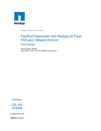
THE CISCO CATALYST 4948E: FIVE PILLARSfour 10 gigabit Ethernet uplinks equipped with 10GBase-SR transceivers. The switch is around 30 inchesdeep, allowing it to fit easily inside most four-post cabinets and racks.Cisco took the term “front-to-back airflow” literally in designing the Catalyst 4948E. The airflow – acritical consideration in designing data centers with hot and cold aisles for maximum cooling efficiency –makes use of the 4948E’s perfectly rectangular shape. Since the only air intake is on the front panel ofthe switch, it cannot be obstructed by placing another switch or other device directly on top of theCatalyst 4948E, where top vents could be blocked.The Catalyst 4948E offers redundant, hot-swappable components such as power supplies and fan trays(something Network Test verified by pulling each component during performance tests). In addition, theCatalyst 4948E supports major loop prevention and failover protocols such as IEEE 802.1D spanning tree(STP); IEEE 802.1w rapid spanning tree (RSTP); and virtually all IP-based routing protocols for layer-3configurations, both for IPv4 and IPv6.Fast Convergence With Flex LinkAlthough spanning tree is widely used to protect against loops and network failures, it carries aperformance penalty: Convergence times following a failure can last up to 45-60 seconds with standardspanning tree, or typically 1-3 seconds with rapid spanning tree. Given that the threshold whereapplication performance can suffer is often measured in milliseconds, these convergence times may betoo high to help avoid degraded performance.Cisco’s Flex Link technology aims to provide link redundancy with much faster convergence times thaneither STP or RSTP. As an alternative to spanning tree, Flex Link works at layer 2, with one switch portacting as backup for another.To verify Flex Link functionality and measure convergence time, Network Test and Cisco engineersconstructed a test bed with four Catalyst 4948E switches. As shown in Figure 1 below, the switches usedFlex Link instead of STP across redundant paths. Engineers then configured a Spirent TestCenter trafficgenerator/analyzer to offer traffic at a rate of 1 million frames per second between two emulated hosts;thus, each dropped frame would correlate to 1 microsecond of convergence time.Page4Initially, test traffic flowed across link 1 as shown in the figure. Engineers then administratively shutdown one link on the test bed, forcing Flex Link to redirect traffic over the backup link, labeled link 2 inthe figure. Finally, Network Test determined convergence time by measuring frame loss.
THE CISCO CATALYST 4948E: FIVE PILLARSFigure 1: Cisco Catalyst 4948E Flex Link Test BedIn five trials, Catalyst 4948E switches using Flex Link converged in an average of 6.6 milliseconds aftera link failure. That is approximately 150 times faster than a best-case scenario with rapid spanning tree,and more than 500,000 times faster than a worst-case scenario using spanning tree. Clearly, Flex Linkoffers superior convergence times compared with STP and RSTP.Control Plane PolicingFor a switch to remain in service, its control-plane CPU must always have enough processing cyclesavailable to handle incoming requests. A switch CPU faces any number of risks: An attacker can spray adevice with malformed packets. A failure elsewhere in the network can cause of flood of MACaddresses, requiring the device to repopulate its address table. A newly attached subnet or service canbring a sudden influx of IGMP join messages. In all these scenarios, the switch CPU is potentiallyvulnerable; utilization can rise to near 100 percent, leaving the switch unable to handle any newrequests and potentially leading to a loss of connectivity.PageTo validate the effectiveness of control plane policing, Network Test used “before” and “after” testsinvolving a mix of benign OSPF and unauthorized multicast traffic. In the “before” test, control planepolicing was disabled on the Catalyst 4948E. Test engineers then established 52 OSPF adjacencies usingSpirent TestCenter, one per switch port, and then configured the test tool to offer multicast traffic at5The control plane policing feature of the Catalyst 4948E offers a safeguard against CPU overload. Byconfiguring a maximum rate at which the control plane will accept traffic, network managers can ensurethe CPU in each Catalyst 4948E will remain available to service new and existing flows.
THE CISCO CATALYST 4948E: FIVE PILLARSline rate to the reserved all-hosts address (224.0.0.1). Since no receivers previously had subscribed toany multicast group, the switch forwarded all multicast packets to the CPU, in turn causing the loss of all52 OSPF adjacencies. The IOS show process cpu command indicated the switch’s CPU was 99percent utilized.The “after” test involved the same routing and traffic parameters, but with control plane policingenabled. This time, there was no change in routing state; all 52 adjacencies remained fully formed. TheIOS command line reported switch CPU utilization at just 8 percent, compared with 99 percent withoutcontrol plane policing.Table 1 below summarizes results from the control plane policing test.Test caseSurviving OSPF adjacenciesControl plane policing disabledControl plane policing enabledCPU utilization05299%8%Table 1: Cisco Catalyst 4948E Control Plane PolicingSPAN Performance and CapacityMirroring is a key capability when it comes to switch management. Copying all traffic to a destinationswitch port for analysis can be invaluable in troubleshooting and capacity planning, but mirroring has acouple of caveats.First, a switch’s SPAN (switched port analyzer) performance must be characterized to determinewhether it can forward all frames when mirroring traffic. A switch without line-rate mirroring capabilitymay drop frames, leaving network engineers without key information needed to solve a given problem.Second, in both campus and data center contexts it is often desirable to configure multiple SPANinstances, for example when multiple teams work on separate issues. Here, the number of concurrentSPAN sessions supported becomes a significant question.Page6The Catalyst 4948E supports up to eight concurrent SPAN sessions using any combination of gigabitEthernet and 10 gigabit Ethernet ports. To validate SPAN performance and capacity, test engineersconfigured eight concurrent SPAN instances using the IOS monitor session command. One ofthese sessions mirrored traffic offered to a 10 gigabit Ethernet port; the remaining sessions monitoredtraffic on gigabit Ethernet ports.
THE CISCO CATALYST 4948E: FIVE PILLARSEngineers then configured the Spirent TestCenter instrument to offer a known quantity 64-byte framesat line rate to each monitored switch port, and to capture traffic on each SPAN port1. The Catalyst 4948Emirrored traffic successfully to all eight SPAN ports, with zero frame loss.Table 2 below summarizes results from the SPAN performance and capacity tests.SPAN port instanceOffered load (fps)Frames ,488,09561,488,09571,488,09581,488,095Table 2: Cisco Catalyst 4948E SPAN Performance and Capacity00000000PageThe use of a hardware-based capture tool is significant here. Software-based analyzers cannot capture all framesat gigabit Ethernet line rates, let alone at 10 gigabit Ethernet rates. A hardware-based capture capability is a mustwhen analyzing line-rate traffic on high-speed networks.71
THE CISCO CATALYST 4948E: FIVE PILLARSPerformance and ScalabilityMention “switch performance” to many network professionals, and the image that inevitably comes tomind is frames moving fast through a device. Certainly that’s important, but high throughput is far fromthe only metric that matters in data center switching. For some applications, latency – the time it takeseach frame to cross the switch – is even more important than throughput. And all switches need to scaleperformance on the control plane as well as the data plane.Control-plane scalability is a key aspect of performance in the data center. To that end, our performancetests, while primarily focused on the data plane, also loaded up the control plane in a number ofinteresting ways:Access control lists (ACLs) have long been considered a security best practice. ACLs require theswitch to inspect every frame before deciding whether to forward it. Unless otherwise noted,the Catalyst 4948E used a 32,292-line ACL in all tests (621 ACL conditions on each of 52 ports).The ACL consisted of 620 “deny” rules followed by a single “permit” rule.Dynamic routing protocols such as EIGRP and OSPF require substantial routing table capacity. InOSPF routing tests, the Catalyst 4948E routed traffic between hosts on 52,000 inter-areanetworks learned using 52 concurrent OSPF adjacencies. Even the world’s largest serviceproviders typically advertise far less than 50,000 inter-area routes on their internal networks.In multicast scenarios, IGMP snooping is needed to switch traffic, and a large multicast route(mroute) capacity may be needed to route traffic. In multicast performance tests, the Catalyst4948E performed IGMPv3 snooping on 28,000 multicast groups. In layer-3 tests, the Catalyst4948E forwarded traffic to 28,000 multicast routes (mroutes).IGMPv3 snooping capacity can scale even higher when external devices function as ProtocolIndependent Multicast (PIM) routers, as they typically would in a data center deployment. In atest of multicast group capacity, the Catalyst 4948E successfully forwarded traffic to 32,767IGMPv3 groups.Virtualization in data centers requires enormous MAC address capacity, with broadcast domainsstretching into the thousands or tens of thousands of addresses. In a test of address cachingcapacity, the Catalyst 4948E forwarded traffic to 55,000 MAC addresses without flooding.Page8Test engineers devised these highly scaled control-plane parameters not to represent some “real-world”network condition, but rather to demonstrate high performance even at the limits of switchperformance. As the following discussion of data-plane performance will show, the switch exhibitedline-rate throughput and low latency across all tests. Thus, there is no performance cost to scalingcontrol-plane parameters to arbitrarily high levels.
THE CISCO CATALYST 4948E: FIVE PILLARSThroughput and LatencyAs defined in RFC 1242, throughput describes the highest rate at which a device can forward traffic withzero frame loss. The zero-loss criterion is especially important in high-speed data centers, where even asingle dropped frame can have an adverse impact on application performance and business operations.The same RFC also defines latency, the time it takes the switch to forward each frame. For delaysensitive applications such as video and voice, latency is an even more important metric thanthroughput. Latency is also a key concern in some vertical industries, such as financial services. Sincelatency is cumulative across switches, the cost of even a little added delay on every switch and routercan have a direct impact on a company’s revenue-bearing application traffic.Significantly, RFC 2544 (the methodology companion to RFC 1242) requires latency to be measured atthe throughput rate. Although virtually all switches exhibit lower delay given less stressful offered loads,testing in that manner does not comply either with the letter or the spirit of the industry-standard IETFbenchmarks. The tests described here measure latency at, and only at, the throughput rate.Also in keeping with the IETF benchmarks’ notion of testing under the most stressful possible conditions,all unicast tests described here use “fully meshed” traffic patterns, where traffic offered to each switchport is destined to all other switch ports. A switch may exhibit lower latency and/or higher throughputusing a less stressful pattern, such as running traffic between pairs of ports, but this is somewhatanalogous to driving a car but never turning left or right.Because a switch buyer has a reasonable expectation of sending traffic to and from any arbitrary set ofports, fully meshed patterns are used here. Again, while it’s possible to craft a less stressful test that willgive a given switch a “better” result, only testing under the most stressful condition will adequatelydescribe switch limits for all users under any condition.The actual patterns in unicast testing involved two full meshes, one apiece for the gigabit Ethernet and10 gigabit Ethernet ports, creating the heaviest possible load on the switch. For multicast testing, testengineers also divided gigabit Ethernet and 10 gigabit Ethernet ports into separate sets, each with onetransmit port and all remaining ports subscribing to all multicast groups. Here again, this creates themost stressful load on the switch.Page9Moreover, all tests were run for a 300-second duration rather than the 30- or 60-second trials oftenused in switch testing; this too is more stressful and better reflects the long-lived flows found in somedata-center applications.
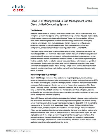
THE CISCO CATALYST 4948E: FIVE PILLARSNetwork Test measured unicast throughput and latency for five different configurations:Layer-2 switching without ACLsLayer-2 switching with a 32,292-line ACL (to determine what cost, if any, the ACL would have)Layer-3 IPv4 static routing with a 32,292-line ACLLayer-3 IPv4 OSPF (52,000 routes, 52 adjacencies) with a 32,292-line ACLLayer-3 IPv6 static routing with a 32,292-line ACLAll five test cases involved traffic offered at line rate from a Spirent TestCenter trafficgenerator/analyzer. In all cases, the Catalyst 4948E forwarded traffic at line rate.Page10Figure 2 below summarizes results from unicast throughput tests, including a comparison with thetheoretical maximum rate for each frame length.Figure 2: Cisco Catalyst 4948E ThroughputThe throughput and latency testing includes a few frame sizes not required by the IETF benchmarkingspecifications. Test engineers used 73-byte frames to show the switch handling an odd frame length; 80-
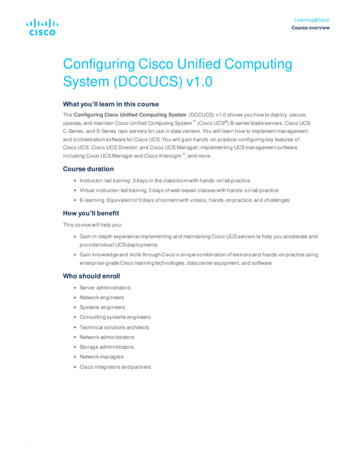
THE CISCO CATALYST 4948E: FIVE PILLARSbyte frames to show IPv6 throughput (see below); and 9,216-byte frames to show jumbo framehandling, a non-standard but nonetheless important consideration in the data center.Throughput was at line rate in all cases shown, meaning the switch never dropped a frame. There wasone exception, not shown, in IPv6 testing. With 78-byte frames (the minimum length supported for IPv6testing), the Catalyst 4948E drops 0.11 percent of offered traffic. With 80-byte frames, as shown here,the Catalyst 4948E routes traffic at 110 million frames per second with zero loss.As a rule, average latency scaled linearly with frame length. Linear scaling of latency is an importantattribute in a store-and-forward device such as the Catalyst 4948E, since it shows switch buffers do notbecome backed up regardless of the number of bytes the switch handles.Table 3 below summarizes unicast average latency measurements.Framelength(bytes)Layer 2, noACLsLayer 2,ACLsLayer 3static, 117.64117.64118.15Table 3: Cisco Catalyst 4948E Unicast Average LatencyLayer 3routed, er 3 IPv6static, rate throughput was also the rule in multicast testing. To assess the Catalyst 4948E’s multicastforwarding capabilities, Network Test used three configurations:Layer-2 switching without ACLsLayer-2 switching with a 32,292-line ACL (to determine what cost, if any, the ACL would have)Layer-3 IPv4 PIM routing with a 32,292-line ACLPageFigure 3 below summarizes throughput results. As in unicast testing, the switch handles multicast trafficat line rate in all tests with zero frame loss. In all cases, measured throughput is identical to thetheoretical maximum.11As noted, all three test cases involved one gigabit Ethernet and one 10 gigabit Ethernet transmitter port,with all remaining ports using IGMPv3 messages to join 28,000 multicast group
Table 2: Cisco Catalyst 4948E SPAN Performance and Capacity 1 The use of a hardware-based capture tool is significant here. Software-based analyzers cannot capture all frames at gigabit Ethernet line rates, let alone at 10 gigabit Ethernet rates. A hardware-based capture capability is a must