Transcription
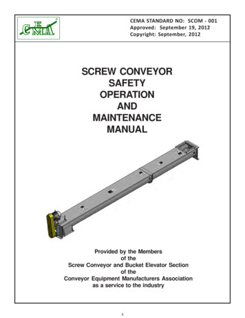
CEMA STANDARD NO: SCOM - 001Approved: September 19, 2012Copyright: September, 2012SCREW d by the Membersof theScrew Conveyor and Bucket Elevator Sectionof theConveyor Equipment Manufacturers Associationas a service to the industry5
CEMA STANDARD NO: SCOM - 001Approved: September 19, 2012Copyright: September, 2012DISCLAIMERThe information provided herein is advisory only.These recommendations provided by CEMA are general in nature and are not intended as asubstitute for professional advice. Users should seek the advice, supervision and/or consultationof qualified engineers, safety consultants, and other qualified professionals.Any use of this publication, or any information contained herein, or any other CEMA publicationis made with the agreement and understanding that the user and the user’s company assumefull responsibility for the designs, safety, specifications, suitability and adequacy of any conveyorsystem, system component, mechanical or electrical device designed or manufactured usingthis information.The user and the user’s company understand and agree that CEMA, its member companies, itsofficers, agents and employees are not and shall not be liable in any manner under any theoryof liability to anyone for reliance on or use of these recommendations. The user and the user’scompanies agree to release, hold harmless and indemnify and defend CEMA, its membercompanies, successors, assigns, officers, agents and employees from any and all claims ofliability, costs, fees (including attorney’s fees), or damages arising in any way out of the use ofthis information.CEMA and its member companies, successors, assigns, officers, agents and employees makeno representations or warranties whatsoever, either expressed or implied, about the informationcontained herein, including, but not limited to, representations or warranties that the informationand recommendations contained herein conform to any federal, state or local laws, regulations,guidelines or ordinances.6
CEMA STANDARD NO: SCOM - 001Approved: September 19, 2012Copyright: September, 2012TABLE OF CONTENTSSECTION A-SAFETYPage 1PDF Page 5SECTION B-INSTALLATIONPage 4PDF Page 8SECTION C-OPERATIONPage 10PDF Page 14SECTION D-MAINTENANCEPage 11PDF Page 15SECTION E-SHUTDOWN AND STORAGEPage 12PDF Page 16SECTION F-TROUBLESHOOTINGPage 15PDF Page 17Page 16PDF Page 19Bolt Torque Guide7
CEMA STANDARD NO: SCOM - 001Approved: September 19, 2012Copyright: September, 2012INTRODUCTIONThe Screw Conveyor and Bucket Elevator Engineering Committee of the CEMA(Conveyor Equipment Manufacturers Association) Engineering Conference wasassigned the task of bringing together, under one cover, the accumulated experienceof many individuals and their companies in an effort to provide a common basis forthe safety, operation and maintenance of screw conveyors.The CEMA Safety, Operation & Maintenance Manual contains instructions for thesafe installation, operation and maintenance of screw conveyors. The reliability andservice life depend on the proper care taken while installing and preparing theequipment for its intended use.Read ALL instructions in this manual and manufacturer's manuals BEFORE installing,operating and maintaining the equipment.8
CEMA STANDARD NO: SCOM - 001Approved: September 19, 2012Copyright: September, 2012SECTION A - SAFETYScrew conveyor safety begins with a plan that considers every possible danger andpotential hazard. Operation and maintenance personnel must be thoroughly trainedin safe operating procedures, recognition of possible hazards, and maintenance ofa safe area around screw conveyors.CEMA has a comprehensive safety program that includes: Warning and Safety Reminder for Screw Conveyors, Drag Conveyors andBucket Elevators - (CEMA Document: SC2004-01) CEMA Safety Label Brochure - (CEMA Document: 201) CEMA Safety Label Placement Guidelines: Screw Conveyor - (CEMA Document: SC-2) Vertical Screw Conveyor - (CEMA Document: SC-3) Screw Conveyor Safety Poster - (CEMA Screw Conveyor Safety Poster) Screw Conveyor, Drag Conveyor and Bucket Elevator Safety Video (CEMA Document: AV6) This video describes key safety practices thatpersonnel must follow when operating and maintaining screw conveyors,drag conveyors and bucket elevators.Screw conveyor accidents can be avoided by implementation and enforcement ofan in-plant safety program. A number of safety precautions are included in thismanual. Carefully study and follow the safety precautions. Remember - accidentsare usually caused by negligence or carelessness.9
CEMA STANDARD NO: SCOM - 001Approved: September 19, 2012Copyright: September, 2012CEMA Document: SC 2004-01WARNING AND SAFETY REMINDERS FORSCREW , DRAG , AND BUCKET ELEVATOR CONVEYORSAPPROVED FOR DISTRIBUTION BY THE SCREW CONVEYOR SECTION OF THECONVEYOR EQUIPMENT MANUFACTURERS ASSOCIATION (CEMA)It is the responsibility of the contractor,installer, owner and user to install, maintainand operate the conveyor, components and,conveyor assemblies in such a manner as tocomply with the Occupational Safety andHealth Act and with all state and local lawsand ordinances and the American NationalStandards Institute (ANSI) B20.1 Safety Code.6. Do not place hands, feet, or any part ofyour body, in the conveyor.In order to avoid an unsafe or hazardouscondition, the assemblies or parts must beinstalled and operated in accordance with thefollowing minimum provisions.9. Do not poke or prod material into theconveyor with a bar or stick inserted throughthe openings.1. Conveyors shall not be operated unlessall covers and/or guards for the conveyor anddrive unit are in place. If the conveyor is to beopened for inspection cleaning, maintenanceor observation, the electric power to themotor driving the conveyor must be LOCKEDOUT in such a manner that the conveyorcannot be restarted by anyone; howeverremote from the area, until conveyor coveror guards and drive guards have been properlyreplaced.2. If the conveyor must have an openhousing as a condition of its use andapplication, the entire conveyor is then to beguarded by a railing or fence in accordancewith ANSI standard B20.1.(Request currentedition and addenda)3. Feed openings for shovel, front loadersor other manual or mechanical equipmentshall be constructed in such a way that theconveyor opening is covered by a grating. Ifthe nature of the material is such that agrating cannot be used, then the exposedsection of the conveyor is to be guarded by arailing or fence and there shall be a warningsign posted.4. Do not attempt any maintenance orrepairs of the conveyor until power has beenLOCKED OUT.5. Always operate conveyor in accordancewith these instructions and those containedon the caution labels affixed to theequipment.7. Never walk on conveyor covers, gratingor guards.8. Do not use conveyor for any purposeother than that for which it was intended.10. Keep area around conveyor drive andcontrol station free of debris and obstacles.11. Eliminate all sources of stored energy(materials or devices that could causeconveyor components to move without powerapplied) before opening the conveyor12. Do not attempt to clear a jammedconveyor until power has been LOCKED OUT.13. Do not attempt field modification ofconveyor or components.14. Conveyorsarenotnormallymanufactured or designed to handle materialsthat are hazardous to personnel. Thesematerials which are hazardous include thosethat are explosive, flammable, toxic orotherwise dangerous to personnel. Conveyorsmay be designed to handle these materials.Conveyors are not manufactured or designedto comply with local, state or federal codesfor unfired pressure vessels. If hazardousmaterials are to be conveyed or if theconveyor is to be subjected to internal orexternal pressure, manufacturer should beconsulted prior to any modifications.CEMA insists that disconnecting and lockingout the power to the motor driving the unitprovides the only real protection againstinjury. Secondary safety devices are available;however, the decision as to their need and thetype required must be made by the ownerassembler as we have no informationregarding plant wiring, plant environment,the interlocking of the screw conveyor with10other equipment, extent of plant automation,etc. Other devices should not be used as asubstitute for locking out the power prior toremoving guards or covers. We caution thatuse of the secondary devices may causeemployees to develop a false sense of securityand fail to lock out power before removingcovers or guards. This could result in a seriousinjury should the secondary device fail ormalfunction.There are many kinds of electrical devices forinterlocking of conveyors and conveyorsystems such that if one conveyor in a systemor process is stopped other equipmentfeeding it, or following it can also beautomatically stopped.Electrical controls, machinery guards, railings,walkways, arrangement of installation,training of personnel, etc., are necessaryingredients for a safe working place. It is theresponsibility of the contractor, installer,owner and user to supplement the materialsand services furnished with these necessaryitems to make the conveyor installationcomply with the law and accepted standards.Conveyor inlet and discharge openings aredesigned to connect to other equipment ormachinery so that the flow of material intoand out of the conveyor is completelyenclosed.One or more warning labels should be visibleon conveyor housings, conveyor covers andelevator housings. If the labels attached to theequipment become illegible, please orderreplacement warning labels from the OEM orCEMA.The Conveyor Equipment ManufacturersAssociation (CEMA) has produced an audiovisual presentation entitled “Safe Operationof Screw Conveyors, Drag Conveyors, andBucket Elevators.” CEMA encouragesacquisition and use of this source of safetyinformation to supplement your safetyprogram.SEE NEXT PAGE FOR SAFETY LABELS
CEMA STANDARD NO: SCOM - 001Approved: September 19, 2012Copyright: September, 2012http://www.cemanet.orgCEMA Safety LabelsCEMA Document: SC 2004-01The CEMA safety labels shown below should be used on screw conveyors, drag conveyors, and bucket elevators. Safetylabels should be placed on inlets, discharges, troughs, covers, inspection doors & drive guards. See CEMA Safety LabelPlacement Guidelines on CEMA Web Site: http://www.cemanet.orgExposed movingparts can causesevere injuryCHR930001LOCK OUT POWERbefore removingguardWalking or standing onconveyor covers orgratings can causesevere injurySTAY OFFCHS991026WARNINGExposed screw andmoving parts can causesevere injuryCVS930010CVS930012Exposed conveyorsand moving partscan cause severeinjuryExposed buckets andmoving parts cancause severe injuryLOCK OUT POWERbefore removingcover or servicingLOCK OUT POWERbefore removingcover or servicingLOCK OUT POWERbefore removingcover or servicingCHR930011PROMINENTLY DISPLAY THESE SAFETY LABELSON INSTALLED EQUIPMENTSEE PREVIOUS PAGE FOR SAFETY REMINDERSNote: Labels alone do not substitute for a thorough in-plant safetytraining program centered on the hazards associated withoperating your installed equipment.Contact CEMA or Your Equipment Manufacturer for ReplacementLabelsCONVEYOR EQUIPMENT MANUFACTURERS ASSOCIATION5624 Strand Court, Suite 2., Naples, Florida Exposed screw andmoving parts cancause severe injuryLOCK OUT POWERbefore removingcover or servicing
CEMA STANDARD NO: SCOM - 001Approved: September 19, 2012Copyright: September, 2012CEMA Safety LabelsPlacement GuidelinesProduct: Bulk Handling EquipmentEquipment: Screw Conveyor“C”“C”“C”To be placed on inlets anddischarges, troughs, covers, and inspection doorsof screw conveyors toprovide warning againstexposed moving partswhile in operation.Exposed movingparts can causesevere injuryLOCK OUT POWERbefore removingguardCHR930001CVS930011“A”Exposed screw andmoving parts cancause severe injuryWalking or standing onconveyor covers orgratings can causesevere injuryLOCK OUT POWERbefore removingcover or servicingSTAY OFFhttp://www.cemanet.orgCHS991026“B”NEAR SIDEFAR SIDEhttp://www.cemanet.orghttp://www.cemanet.orgTo be placed onremovable guards towarn that operation ofthe machinery withguards removed wouldexpose chains, belts,gears, shafts, pulleys,couplings, etc. whichcreate hazards“C”USE LABEL “A” ON BELT GUARDUSE LABEL “B” ON ENDS OF TROUGH, MIDDLE OFCOVERS AND AT INLET OPENING.USE LABEL “C: ON TOP OF COVERS12SC-2
CEMA STANDARD NO: SCOM - 001Approved: September 19, 2012Copyright: September, 2012CEMA Safety LabelsPlacement GuidelinesProduct: Bulk Handling EquipmentEquipment:USE LABEL “A” ON BELT GUARDVertical Screw ConveyorUSE LABEL “B” ON ENDS OF TROUGH,ON INTAKE INSPECTION DOOR,ANDBOTH SIDES OF DISCHARGE SPOUT"A"Exposed movingparts can causesevere injuryBOTHSIDESLOCK OUT POWERbefore removingguardCHR930001http://www.cemanet.orgTo be placed onremovable guards towarn that operation ofthe machinery withguards removed wouldexpose chains, belts,gears, shafts, pulleys,couplings, etc. whichcreate hazards“A”"B"To be placed on inletsand discharges, troughs,covers, and inspectiondoors of screw conveyors to provide warning against exposedmoving parts while inoperation.NEAR SIDEFAR SIDECVS930011Exposed screws andmoving parts cancause severe injury"B"LOCK OUT POWERbefore removingcover or servicinghttp://www.cemanet.org"B"SC-313
CEMA STANDARD NO: SCOM - 001Approved: September 19, 2012Copyright: September, 201214
CEMA STANDARD NO: SCOM - 001Approved: September 19, 2012Copyright: September, 2012SCREW CONVEYOR COMPONENTSBill of MaterialsItem15Descripton1Screw2Screw with Bare Pipe at Discharge3Coupling Bolts (Not Shown)4Coupling Shaft5Hanger with Bearing6Tail End Trough End7Trough End for Screw Conveyor Drive8Trough End for Screw Conveyor Drive9Trough with Discharge Spout10Seal11Bearing12Tail Shaft1314Flanged CoverFlanged Cover with Inlet15Buttstrap16Screw Conveyor Drive Unit with Motor Mount,V-Belt Drive, and Guard
123456789101112131415161718KSTANDARD LIFT DETAIL FOR SCREW CONVEYORJCENTER ALL LIFTING LUGS (BY OTHERS)I BEAM (BY OTHERS)ILIFTING STRAPS (BY OTHERS)DO NOT USE CHAINSHGF1/3 OF TOTAL LENGTH1/3 OF TOTAL LENGTH1/3 OF TOTAL LENGTHELIFTING DETAILALL LIFTING APPARATUSES BY OTHERSDC*NOTES:1- NO SINGLE UNSUPPORTED LENGTH TO EXCEED 12'-0"2- ALL LIFTING APPARATUSES TO BE SIZED AND SUPPLIED BY OTHERSREVISIONSNO.DATEBYDESCRIPTIONSECTION No.KWS MANUFACTURING CO., LTD.PAGE No.3041 CONVEYOR DRIVEBURLESON, TX 76028Phone: (817) 295-2247Fax: (817) 447-8528Website: www.kwsmfg.comEmail: sales@kwsmfg.comCONVEYORLIFTSTANDARDENGINEERING STANDARDDRAWING BY: CHECKED BY:LAM16BDATE11/22/2011SCALEN/ADRAWING NO.CONVEYOR LIFT STDAREV.
CEMA STANDARD NO: SCOM - 001Approved: September 19, 2012Copyright: September, 2012SECTION B - INSTALLATIONRECEIVING1.2.3.4.Screw conveyors may be ordered as individual components with all the assembly operations performed in the field,or assembled completely by the manufacturer, with drawings and bill of materials.Immediately upon receipt all items in the shipment should be checked against shipping papers for shortages andinspected for damage.Items to be inspected include troughs, screws, covers and drive units.DO NOT ATTEMPT TO INSTALL DAMAGED COMPONENTS OR ASSEMBLIES.LIFTING AND MOVING1.2.3.4.5.6.Extreme care must be taken to prevent damage when moving assembled conveyors or components.Spreader bars with slings are the recommended support method for lifting.Unsupported span should be no greater than 12 feet.NEVER LIFT A CONVEYOR WITH ONLY ONE SUPPORT POINT.Unusually heavy items such as drives or gates shall be considered when choosing support points because of loadbalance and their bending effect.Shop assembled conveyors are typically match marked and shipped in the longest sections for practical 15.16.The mounting surface for supporting the conveyor must be level and true.Screw conveyor troughs must be assembled straight and true with no distortion.Place troughs in proper sequence with discharge spout properly located.Connect the joints loosely. DO NOT TIGHTEN BOLTS.Assemble each trough end to proper end of conveyor.Attach piano wire full length of conveyor at centerline. Make sure piano wire is pulled tight. Refer to Figure 1 at theend of this section.Tighten trough flange bolts keeping the trough assembly true to piano wire. Alignment must be checked in bothhorizontal and vertical directions. Maximum deviation in either direction at any point along the length of theconveyor is 1/8". Torque bolts to proper torque rating per Chart A.Anchor trough assembly to mounting surface. Make sure entire length of trough is straight and true. CEMArecommends supporting trough assemblies every 10 to 12 feet. Saddles and feet may be required.Mount drive or thrust unit on correct trough end. Drive or thrust units are normally located at discharge end ofconveyor. Make sure drive or thrust unit is centered in seal and trough end openings. Torque bolts to proper torquerating per Chart A.Place the first screw section in the trough starting at the drive or thrust end. Install screw so end lugs are oppositecarrying side of flight.Insert screw onto drive shaft and install coupling bolts. DO NOT TIGHTEN COUPLING BOLTS.Insert coupling shaft into opposite end of screw and install coupling bolts. DO NOT TIGHTEN COUPLING BOLTS.Pull screw section away from drive or thrust unit to seat thrust connection.Insert hanger onto coupling shaft.Raise hanger and screw section until hanger top bar is flush with top of trough. Make sure correct clearance existbetween outside diameter of screw and inside of trough. Match mark and drill troughs to mount hanger assembly.Insert hanger assembly bolts and hand tighten.Assemble screw sections, couplings and hangers until all are installed by repeating steps 10 through 15. Install screwsections so flighting is 180-degrees from end of flighting of previous screw section.17
CEMA STANDARD NO: SCOM - 001Approved: September 19, 2012Copyright: September, 201217. Center hanger bearings between screw sections. Torque hanger assembly bolts to proper torque rating per Chart A.18. Assemble seal and bearing to opposite trough end. Make sure end shaft is centered in seal and trough end openings.Torque bolts to proper torque rating per Chart A.19. Insert end shaft through end bearing and into last screw section and install coupling bolts. DO NOT TIGHTENCOUPLING BOLTS.20. Rotate entire screw assembly to check alignment and adjust hanger assemblies as required.21. Torque ALL coupling bolts to proper torque rating. Over tightening of coupling bolts could result in failure in tension.CEMA recommends tightening coupling bolts to 75-percent of the values given in the Bolt Torque Guide to eliminateover tightening of coupling bolts.22. Adjust seals as required.23. Remove all debris from conveyor.24. Install covers in proper sequence starting at inlet end and attach with provided fasteners.25. Lubricate drive and all bearings in accordance with manufacturer's instructions. DRIVES GENERALLY SHIPPEDWITHOUT OIL.26. MAKE SURE ALL CEMA SAFETY LABELS ARE IN PROPER LOCATIONS.CEMA COMMONLY USED PIANO WIRE SETUPPIANO WIRE ATTACHED TO TOP OF CONVEYOR ON SIDEOPTIONAL PIANO WIRE SETUPPIANO WIRE ATTACHED TO CENTERLINE OF CONVEYOR ON SIDEFigure 1 - Piano Wire Setup Diagrams18
CEMA STANDARD NO: SCOM - 001Approved: September 19, 2012Copyright: September, 2012SECTION C - OPERATIONBEFORE INITIAL START-UP:1.2.3.4.5.6.7.LOCKOUT/TAGOUT ALL POWER.Lubricate all bearings in accordance with manufacturer's instructions.Lubricate all gear reducers in accordance with manufacturer's instructions. Gear reducers are normally shippedwithout lubrication.Check conveyor to ensure all tools and foreign materials have been removed.Turn drive unit by hand to check for alignment and obstructions.Check conveyor to ensure all covers, guards
is made with the agreement and understanding that the user and the user’s company assume full responsibility for the designs, safety, specifications, suitability and adequacy of any conveyor . (CEMA) It is the responsibility of the contractor, installer, owner and user to install, maintain . the