Transcription
NIH Public AccessAuthor ManuscriptInt J Artif Organs. Author manuscript; available in PMC 2012 March 22.NIH-PA Author ManuscriptPublished in final edited form as:Int J Artif Organs. 2010 October ; 33(10): 731–737.Fabrication of Custom-Shaped Grafts for Cartilage RegenerationSeungbum Koo, PhD1, Brian A. Hargreaves, PhD2, Garry E. Gold, MD2, and Jason L.Dragoo, MD31 School of Mechanical Engineering, Chung-Ang University, Seoul, South Korea2Department of Radiology, Stanford University, Stanford, California, USA3Department of Orthopedic Surgery, Stanford University, Stanford, California, USAAbstractNIH-PA Author ManuscriptTransplantation of engineered cartilage grafts is a promising method to treat diseased articularcartilage. The interfacial areas between the graft and the native tissues play an important role inthe successful integration of the graft to adjacent native tissues. The purposes of the study were tocreate a custom shaped graft through 3D tissue shape reconstruction and rapid-prototype moldingmethods using MRI data, and to test the accuracy of the custom shaped graft against the originalanatomical defect.An iatrogenic defect on the distal femur was identified with a 1.5 Tesla MRI and its shape wasreconstructed into a three-dimensional (3D) computer model by processing the 3D MRI data.First, the accuracy of the MRI-derived 3D model was tested against a laser-scan based 3D modelof the defect. A custom-shaped polyurethane graft was fabricated from the laser-scan based 3Dmodel by creating custom molds through computer aided design and rapid-prototyping methods.The polyurethane tissue was laser-scanned again to calculate the accuracy of this processcompared to the original defect.NIH-PA Author ManuscriptThe volumes of the defect models from MRI and laser-scan were 537 mm3 and 405 mm3,respectively, implying that the MRI model was 33% larger than the laser-scan model. The average( SD) distance deviation of the exterior surface of the MRI model from the laser-scan model was0.4 0.4 mm. The custom-shaped tissue created from the molds was qualitatively very similar tothe original shape of the defect. The volume of the custom-shaped cartilage tissue was 463 mm3which was 15% larger than the laser-scan model. The average ( SD) distance deviation betweenthe two models was 0.04 0.19 mm.Custom-shaped engineered grafts can be fabricated from standard sequence 3-D MRI data with theuse of CAD and rapid-prototyping technology, which may help solve the interfacial problembetween native cartilage and graft, if the grafts are custom made for the specific defect. The majorsource of error in fabricating a 3D custom shaped cartilage graft appears to be the accuracy of aMRI data itself; however, the precision of the model is expected to increase by the utilization ofadvanced MR sequences with higher magnet strengths.Corresponding author: Jason L. Dragoo, MD, Assistant Professor, Department of Orthopaedic Surgery, Stanford University, 450Broadway, MC 6342, Redwood City, CA 94063, o-(650) 721-7800, f-(650) 721-3470, jdragoo@stanford.edu.Contact information of other authorsSeungbum Koo, PhD, Assistant Professor, School of Mechanical Engineering, Chung-Ang University, 221 Heukseok-dong, Dongjakgu, Seoul, South Korea 156-756, Phone: 82-2-820-5876, Fax: 82-2-814-9476, skoo@cau.ac.krBrian A. Hargreaves, PhD, Assistant Professor, Department of Radiology, Stanford University, 1201 Welch Rd. Lucas MRS Center,Room P020B, Stanford, CA 94305-5488, bah@stanford.eduGarry E Gold, MD, Associate Professor, Department of Radiology, Stanford University, 300 Pasteur Dr., Grant Bldg. S0-68B,Stanford, CA 94305-5105, Phone: (650) 725-8018, gold@stanford.edu
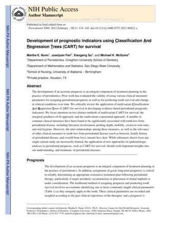
Koo et al.Page 2Key Index TermsNIH-PA Author ManuscriptCartilage; Tissue Engineering; Custom-shaped; MRI; rapid prototyping; CAD; computer aideddesign; Fused Deposition ModelingIntroductionCartilage defects seldom heal as the chondrocytes have low metabolism and regenerativecapacity (1), which may result in degenerative joint disease. Transplantation of engineeredcartilage grafts is a promising method to treat articular cartilage defects (2). The implantedgraft is expected to integrate with adjacent tissues, remodel itself to form the structural andbiochemical tissue, and withstand mechanical stresses within the joint (3). Numerous tissueengineering methods have been described to create cartilage grafts in vivo and in vitro. Thesuccess of these procedures relies on the integration of the graft to adjacent native tissues(4). Therefore, recent studies have focused on preparing custom-shaped grafts to minimizegraft-defect mismatch.NIH-PA Author ManuscriptTsuchiya et al. incorporated poly DL-lactic-co-glycolic acid sheets and collagenmicrosponges in their openings to repair bone defects (5). They fabricated this material intodesired shapes by changing the shape of the poly sheets. Our laboratory previously reporteda cartilage tissue engineering method in vivo using adipose-derived stem cells, fibrin glueand growth factors (6). These tissue engineering methods have begun to fabricate cartilagegrafts into arbitrary shapes to match the complex shape of the defect. This allows thecartilage graft to be implanted without excising and widening the damaged cartilage area.The graft, therefore, would have minimum interfacial mechanical stresses with adjacentbones and cartilage, which will promote the viability of the chondrocytes and the formationof collagen networks (7,8).Magnetic resonance imaging (MRI) provides a non-invasive high-resolution method todetect and create three-dimensional models (9). Detectible sizes of drill holes in articularcartilage showed that 2 mm and 3 mm holes on the distal femur were detectable in MRI withthe aid of intra-articular saline and Gd-DTPA injections, respectively (10). Graichen et al.also investigated the accuracies in the determination of the 3D shapes of cylindrical holes oncartilage (11). The accuracy of measuring cartilage thicknesses (12) by MRI have beeninvestigated but the accuracy of measuring arbitrary defect shapes using MRI has not beenevaluated. In our previous study, we utilized a novel three-dimensional laser scanningtechnique to evaluate the accuracy of articular cartilage thickness measured in MRI (12).NIH-PA Author ManuscriptThe purpose of this study was to create a custom shaped cartilage graft through 3D tissueshape reconstruction and rapid-prototyping methods, and to test the accuracy of the customshaped cartilage graft against the anatomic defect on a human knee.MethodsSpecimen preparation and MR imagingA fresh-frozen cadaveric human knee was thawed at a room temperature and an artificialdefect similar to an osteochondritis dissecans lesion, which includes injury to both cartilageand bone, was surgically created on the distal femoral surface as shown in Figure 1a. Thesoft tissues were surgically repaired with 2-O Vicryl, and remainder of the knee was keptintact.Int J Artif Organs. Author manuscript; available in PMC 2012 March 22.
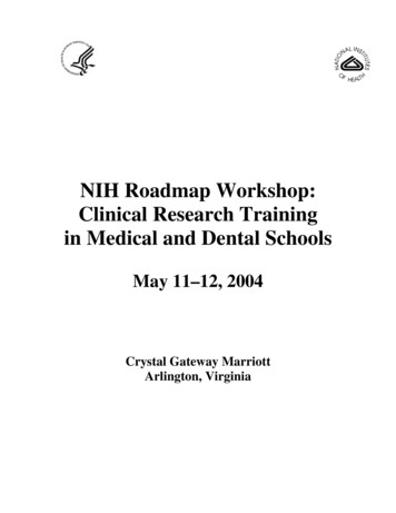
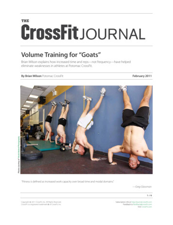
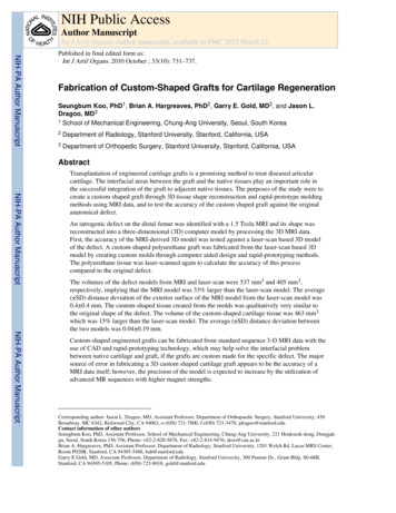
Koo et al.Page 3NIH-PA Author ManuscriptMR images of the knee were obtained with a fat-suppressed Spoiled Gradient Recalled Echosequence (13) with the parameters of TR 19.40 ms, TE 4.60 ms, Flip Angle 20 degreesand Field of View 16 16 8.6 cm in a 1.5T GE Signa scanner using an 8-channel knee coil.The slice thickness was 0.7 mm and the in-plane resolution was 0.625 0.625 mm (Figure1b).Creating a 3D model of the defectThe MR images were loaded into our custom software (12). The boundaries of the distalfemur including articular cartilage were identified in the MR images and semi-automaticallysegmented using Spline tools in the software followed by manual correction for all slices ofMR images. The segmented boundaries were combined and made into a three-dimensionalmodel using the custom software. The accuracy of 3D model created using custom softwarewas validated in a previous study (12). The defect on the distal femur was incorporated intoa separate 3D model by creating a negative shape of the distal femur using 3D polygonmanipulation software (Rapidform, Inus Technology, Seoul, South Korea) (Figure 4a). Asmooth surface was created on top of the defect using the curvatures of the intact cartilagearound the defect. The smooth surface was stitched with the polygons of the defect to createa 3D defect model.Creating molds with computer aided design and rapid-prototypingNIH-PA Author ManuscriptThe 3D defect model was placed in the middle of two mold blocks consisting of top andbottom blocks (Figure 2). The size of the bounding box of the defect was 17 16 6 mm3and the size of each top and bottom block was 60 60 20 mm3. The mold was designed tokeep the smooth surface shape of the articular surface intact when the fragile moldedcartilage tissue would be peeled off the mold, thus the boundary of the top surface of thedefect model was used as a parting line (Figure 2b). The parting line along the top surfacewas connected to the boundaries of the top and bottom molds to create a parting plane(Figure 2c and 2d). The defect model was separated into two parts along the boundary of thesurface. The top surface and the remainder of the defect were connected to the parting planein the top and bottom molds, respectively, to create complete shapes of the top and bottommolds. A 3mm injection channel was made at the bottom mold to keep the smooth topsurface uninterrupted. The matrix gel was then injected into the mold through the bottom ofthe defect (Figure 2e).NIH-PA Author ManuscriptThe computer models of the top and bottom molds were exported as .STL files for rapidprototyping fabrication. The molds were created using the Fused Deposition Modeling(FDM) technique (Redeye RPM, Eden Prarie, MN). Briefly, plastic filament(Polycarbonate-ISO) was unwound from a coil and supplied to an extrusion nozzle whichwas heated to melt the material. The material was then extruded onto a platform, which wasmoved in both horizontal and vertical directions, and directly controlled by computer-aidedmanufacturing (CAM) software. The mold was produced by extruding small beads of PCISO material to form layers, as the material hardened immediately after extrusion from thenozzle (Figure 3a). The sterilizable thermoplastic Polycarbonate-ISO (PC-ISO) was used asit is a medical grade plastic which meets both ISO 10993-1 and USP Class VI standards.Testing the accuracy of the custom shaped tissue created from the moldsThe ability of the molds to create a custom-shaped graft was tested by the use of liquidpolyurethane (VytaFlex 10, Reynolds Advanced Materials, Hollywood, CA). This materialwas injected into the molds through the 3 mm injection channel (Figure 3b). The molds weretaken apart along the parting plane 16 hours (matrix specific) after injection and the defectshaped polyurethane was easily peeled off from the mold.Int J Artif Organs. Author manuscript; available in PMC 2012 March 22.
Koo et al.Page 4NIH-PA Author ManuscriptThe accuracy of the 3D MRI fabrication model used to create the molds was tested againstthe anatomic defect shape from the distal femur. The cadaveric knee was then dissected ofall soft tissues to obtain the distal femur. The surface of the distal femur with the targetdefect was laser-scanned using a desktop laser-scanner (Model 15, Cyberware, Monterey,California, USA) (Figure 4b). The accuracy of the scanner was 50 μm in depth and the pitchbetween scan lines was 300 μm. The laser-scan was performed in multiple views andcombined using Cydir (Cyberware, Monterey, California, USA) to create a complete shapeof the distal femur with the defect. Using the same method as the 3D MRI fabricationmodel, a negative shape of the distal femur was created from the laser-scan assuming asmooth cartilage surface.The two 3D defect models from MRI and laser-scan were aligned and compared in 3Dpolygon manipulation software. The average distance deviation on the exterior surface andthe volume difference were quantified.The accuracy of the custom-shaped graft made of polyurethane (see above) from the laserscan prototype was tested against the 3D MRI fabrication model using Rapidform Software(Inus Technology, Seoul, South Korea). The average distance deviation and the volumedifference were quantified.NIH-PA Author ManuscriptResultsThe volumes of the defect models obtained from the MRI and laser-scans were 537 mm3and 405 mm3, respectively, implying that the MRI model was 33% larger than the laser-scanmodel. The surface areas were 479 mm2 and 431 mm2 for the MRI model and the laser-scanmodel, respectively. The average ( Standard Deviation) distance deviation of the exteriorsurface of the MRI model from the laser-scan model was 0.4 0.4 mm. The distancedeviation map is shown in Figure 5.The custom-shaped grafts created from the molds were directly compared to the laserscanned original defect used to create the molds. The two models were qualitatively verysimilar (Figure 6). The volume and the surface area of the custom-shaped cartilage tissuewere 463 mm3 and 444 mm2, respectively, which were 15% and 3% larger than the laserscan model (405 mm3 and 431 mm2, respectively) The average ( Standard Deviation)distance deviation between the two models was 0.04 0.19 mm.DiscussionNIH-PA Author ManuscriptThis study demonstrated that the creation of a custom-shaped engineered graft from ananatomic defect on a distal femur of an otherwise intact knee can be fabricated using 3DMRI data and rapid-prototype manufacturing techniques. This process was based on theassumption that the engineered grafts can be constructed using injectable matrix materialscombined with autologous stem cells and growth factors as reported in our previous study(6). In many cases, the major reason for failure of cartilage grafts is increased interfacialstresses between the native and the transplanted tissues due to graft-defect mismatch, whichaffects cell viability and collagen formation (7,8). This type of failure may be minimized byinserting a bone-cartilage tissue graft which matches the shape of the defect.With these assumptions in mind, the 3D defect model was created from non-invasive MRIdata through manual segmentation and a 3D geometry reconstruction process. The MRIbased model was very similar to the original defect shape qualitatively, but showed 33%overestimation in the volume. Actually, the absolute volume overestimation (132 mm3) wassmall, but the large percentage of error was due to the small volume of the defect. Theoverestimation in the volume may actually prove useful in the process of surgicalInt J Artif Organs. Author manuscript; available in PMC 2012 March 22.
Koo et al.Page 5NIH-PA Author Manuscriptimplantation, by providing the ability to press-fit the graft into the defect without fixation orto create a safe buffer in case the surrounding cartilage margin is unhealthy and needs minordebridement.A previous study has reported the accuracy in detecting in-vivo 3D cylindrical defects intibial cartilage with 1.5T MRI. The average error in detecting the diameters of cylindricaldefects with 3, 5 and 8 mm diameters were 1.29, 1.03 and 0.10 mm, respectively (11). Ourresults, with an average error of 0.4 mm for the overall surface, were very similar to the 0.65and 0.52 mm deviations in radii for the 3 and 5 mm defects in the previous study. We canalso infer using results from Graichen et al. (11) that the error in detecting the shape of thedefect would increase for a smaller defect. Therefore, the size of the defect should beconsidered when using this technique.NIH-PA Author ManuscriptThe resolution of MR imaging data using a 1.5 Tesla (T) magnet was 0.625 0.625 0.7 mm3for each voxel. The shape of the cartilage tissue from the molds was very close to theoriginal defect used in creating the molds. The average distance deviation of the graftproduced via laser scan was 0.04 0.19 mm with a 95% confidence interval of 0.33 and0.41 mm, which is very similar compared with the average distance deviation of the MRIbased model (0.4 mm). Currently, the major source of error in manufacturing a 3D customshaped cartilage graft appears to be the accuracy of a MRI data, but the accuracy of themodel is expected to increase by utilizing advanced musculoskeletal MR sequences withhigher magnet strengths (3T) (14,15,16). Furthermore, since the location of the defect isoften known, the MRI could target this location by using a small surface coil to provide thesignal noise reduction (SNR) necessary to obtain higher resolution images. A laser-scanbased defect model was used as a standard in testing the accuracy of the MRI custom-shapedgrafts. The accuracy and the methods of creating 3D models of tissue shapes from laserscans have been comprehensively presented in a previous study (12).A new method of creating parting line was introduced in this study for designing moldsrequiring a smooth surface to recreate a seamless articular surface. The position of theparting line would also allow the ability to easily peel-off of the tissue from the moldswithout disruption of the smooth articular surface.The molds were created using the using fused deposition modeling (FDM) rapid-prototypingtechnique. Medical grade, sterilizable thermoplastic material was used to allow use in tissueengineering applications. This technique also allows the molds to be manufactured with anaccuracy of 0.127 mm. Future improvement in thermoplastics should allow the use of 3Dprinting techniques, which are rapid and much less expensive than FDM.NIH-PA Author ManuscriptConclusionThis investigation proves the concept that custom-shaped engineered grafts can be fabricatedfrom standard sequence 3-D MRI data with the use of CAD and rapid-prototypingtechnology. Qualitatively, the articular defect details were captured on the mold surfacesusing the MRI-based 3D data, and the overall accuracy, or average distance deviation, was0.4 mm. The custom-shaped graft was very similar to the original anatomic defect bothqualitatively and quantitatively. The overall accuracy of the custom-shaped grafts shouldincrease with more accurate 3D MRI data, which could be achieved through furtheradvancements in the resolution, contrast and magnet strength.References1. Martin JA, Buckwalter JA. Post-traumatic osteoarthritis: the role of stress induced chondrocytedamage. Biorheology. 2006; 43:517. [PubMed: 16912423]Int J Artif Organs. Author manuscript; available in PMC 2012 March 22.
Koo et al.Page 6NIH-PA Author ManuscriptNIH-PA Author ManuscriptNIH-PA Author Manuscript2. Vunjak-Novakovic, G.; Goldstein, SA. Biomechanical principles of cartilage and bone tissueengineering. In: Mow, VC.; Huiskes, R., editors. Basic orthopaedic biomechanics and mechanobiology. 3. Philadelphia: Lippincott Williams & Wilkins; 2005. p. 343-407.3. Andriacchi TP, Briant PL, Bevill SL, Koo S. Rotational Changes at the Knee After ACL InjuryCause Cartilage Thinning. Clin Orthop Relat Res. 2006; 442:39. [PubMed: 16394737]4. Brittberg M, Lindahl A, Nilsson A, Ohlsson C, Isaksson O, Peterson L. Treatment of deep cartilagedefects in the knee with autologous chondrocyte transplantation. N Engl J Med. 1994; 331:889.[PubMed: 8078550]5. Tsuchiya K, Mori T, Chen G, Ushida T, Tateishi T, Matsuno T, Sakamoto M, Umezawa A. Customshaping system for bone regeneration by seeding marrow stromal cells onto a web-likebiodegradable hybrid sheet. Cell Tissue Res. 2004; 316:141. [PubMed: 14999559]6. Dragoo JL, Carlson G, McCormick F, Khan-Farooqi H, Zhu M, Zuk PA, Benhaim P. Healing fullthickness cartilage defects using adipose-derived stem cells. Tissue Eng. 2007; 13:1615. [PubMed:17518742]7. DiMicco MA, Sah RL. Integrative cartilage repair: adhesive strength is correlated with collagendeposition. J Orthop Res. 2001; 19:1105. [PubMed: 11781012]8. Moretti M, Wendt D, Schaefer D, Jakob M, Hunziker EB, Heberer M, Martin I. Structuralcharacterization and reliable biomechanical assessment of integrative cartilage
Creating molds with computer aided design and rapid-prototyping The 3D defect model was placed in the middle of two mo