Transcription
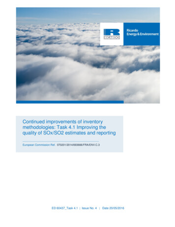
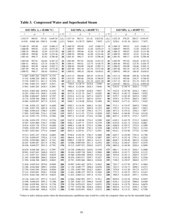
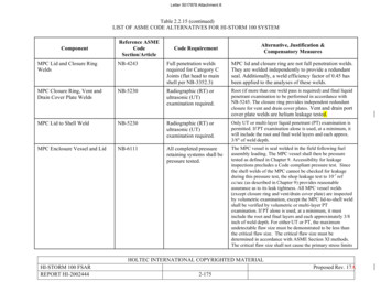
Letter 5017878 Attachment 8Table 2.2.15 (continued)LIST OF ASME CODE ALTERNATIVES FOR HI-STORM 100 SYSTEMComponentReference ASMECodeSection/ArticleCode RequirementAlternative, Justification &Compensatory MeasuresMPC Lid and Closure RingWeldsNB-4243Full penetration weldsrequired for Category CJoints (flat head to mainshell per NB-3352.3)MPC lid and closure ring are not full penetration welds.They are welded independently to provide a redundantseal. Additionally, a weld efficiency factor of 0.45 hasbeen applied to the analyses of these welds.MPC Closure Ring, Vent andDrain Cover Plate WeldsNB-5230Radiographic (RT) orultrasonic (UT)examination required.Root (if more than one weld pass is required) and final liquidpenetrant examination to be performed in accordance withNB-5245. The closure ring provides independent redundantclosure for vent and drain cover plates. Vent and drain portcover plate welds are helium leakage tested.MPC Lid to Shell WeldNB-5230Radiographic (RT) orultrasonic (UT)examination required.Only UT or multi-layer liquid penetrant (PT) examination ispermitted. If PT examination alone is used, at a minimum, itwill include the root and final weld layers and each approx.3/8" of weld depth.MPC Enclosure Vessel and LidNB-6111All completed pressureretaining systems shall bepressure tested.The MPC vessel is seal welded in the field following fuelassembly loading. The MPC vessel shall then be pressuretested as defined in Chapter 9. Accessibility for leakageinspections precludes a Code compliant pressure test. Sincethe shell welds of the MPC cannot be checked for leakageduring this pressure test, the shop leakage test to 10-7 refcc/sec (as described in Chapter 9) provides reasonableassurance as to its leak tightness. All MPC vessel welds(except closure ring and vent/drain cover plate) are inspectedby volumetric examination, except the MPC lid-to-shell weldshall be verified by volumetric or multi-layer PTexamination. If PT alone is used, at a minimum, it mustinclude the root and final layers and each approximately 3/8inch of weld depth. For either UT or PT, the maximumundetectable flaw size must be demonstrated to be less thanthe critical flaw size. The critical flaw size must bedetermined in accordance with ASME Section XI methods.The critical flaw size shall not cause the primary stress limitsHI-STORM 100 FSARREPORT HI-2002444HOLTEC INTERNATIONAL COPYRIGHTED MATERIAL2-175Proposed Rev. 17A
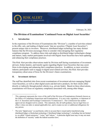
Letter 5017878 Attachment 8Table 2.III.3: BWR FUEL ASSEMBLY CHARACTERISTICS FOR LOADING INMPC-68M (Note 1)Fuel Assembly Arrayand Class10x10F10x10G10x10I(Note 12)10x10J(Note 13)11x11A(Note 14)Clad Material (Note 2)ZrZrZrZrZrDesign Initial U (kg/assy.)(Note 3) 192 188 194 194 194Maximum Planar-AverageInitial Enrichment (wt.%235U) (Note 8, 9)4.7(Note 7)4.75(Note 10)4.84.84.8Maximum Planar-AverageInitial Enrichment withPartial Gadolinium Credit(wt.%235U) (Note 11)5.05.05.05.05.0 5.0 5.0 5.0 5.0 5.0No. of Fuel Rod Locations92/78(Note 4)96/8491/7996/80112/92Fuel Clad O.D. (in.) 0.4035 0.387 0.4047 0.3999 0.3701Fuel Clad I.D. (in.) 0.3570 0.340 0.3559 0.3603 0.3252Fuel Pellet Dia. (in.) 0.3500 0.334 0.3492 0.3531 0.3193Fuel Rod Pitch (in.) 0.510 0.512 0.5100 0.5149 0.4705Design Active FuelLength (in.) 150 150 150 150 150No. of Water Rods(Note 6)25(Note 5)111Water Rod Thickness (in.) 0.030 0.031 0.0315 0.0297 0.0340Channel Thickness (in.) 0.120 0.060 0.100 0.0938 0.100Initial Rod MaximumEnrichment (wt.% 235U)HOLTEC INTERNATIONAL COPYRIGHTED MATERIALHI-STORM 100 FSARREPORT HI-20024442.III-7Proposed Rev.17A
Letter 5017878 Attachment 89.1.6Thermal Acceptance TestsThe thermal performance of the HI-STORM 100 System, including the MPCs and HI-TRACtransfer casks, is demonstrated through analysis in Chapter 4 of the FSAR. Dimensionalinspections to verify the item has been fabricated to the dimensions provided in the drawingsshall be performed prior to system loading. Following the loading and placement on the storagepad of the first HI-STORM System placed in service, the operability of the natural convectivecooling of the HI-STORM 100 System shall be verified by the performance of an air temperaturerise test. A description of the test is described in FSAR Chapter 8.In addition, the technical specifications require periodic surveillance of the overpack air inlet andoutlet vents or, optionally, implementation of an overpack air temperature monitoring program toprovide continued assurance of the operability of the HI-STORM 100 heat removal system.9.1.6.1Supplemental Cooling System Thermal Acceptance TestingThe following thermal acceptance testing shall be performed following fabrication and prior tothe first implementation of the HI-DRIP and the Dry Ice Jacket Supplemental Cooling system.The thermal acceptance test will be performed and documented a single time for each method tovalidate the thermal analysis. (see also Section 2.2.1.7 and 2.2.1.8)9.1.6.1.1HI-DRIP Supplemental Cooling Thermal Acceptance Testing[PROPIETARY INFORMATION WITHHELD IN ACCORDANCE WITH 10 CFR 2.390]Testing shall be performed in accordance with written and approved procedures anddocumented.9.1.6.1.2Dry Ice Jacket Supplemental Cooling Thermal Acceptance Testing[PROPIETARY INFORMATION WITHHELD IN ACCORDANCE WITH 10 CFR 2.390]Testing shall be performed in accordance with written and approved procedures anddocumented.9.1.7Cask IdentificationEach MPC, HI-STORM overpack, and HI-TRAC transfer cask shall be marked with a modelnumber, identification number (to provide traceability back to documentation), and the emptyweight of the item in accordance with the marking requirements specified in 10 CFR 72.236(k).HOLTEC INTERNATIONAL COPYRIGHTED MATERIALHI-STORM 100 FSARProposed Rev. 17AREPORT HI-20024449-16
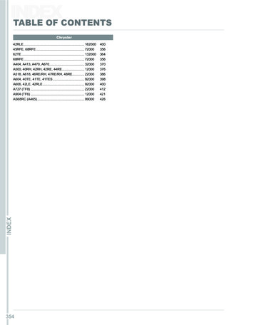
Letter 5017878 Attachment 82.II.1.5.1 Design Heat LoadMPC-32M is designed for the uniform and regionalized fuel loading strategies as described in Subsection2.0.1 and 2.1.9. The design basis uniform heat load defined in Section 2.1.9, Qd, for MPC-32M isprovided in Table 2.II.1.5. The regions for the MPC-32M are presented in Table 2.II.1.3. Additionally,two discrete heat load patterns have been defined for MPC-32M as shown in Figures 2.II.1.2 and 2.II.1.3.The quadrants for the MPC-32M are defined in Table 2.II.1.4 and the maximum quadrant decay heatloads are given in Table 2.II.1.5. The same fuel cladding temperature limits as those for the regionalizedloading configuration apply to these heat load patterns.The MPC-32M is designed to accommodate variable fuel heights. For fuel with a longer active fuel lengththat the reference fuel (144in), the total heat load, quadrant heat load limits and specific heat load limit ineach cell may be increased by the ratio SQRT (L/144), where L is the active length of the fuel in inches.For fuel with a shorter active fuel length than the reference fuel (144in), the total heat load, quadrant heatload limits and specific heat load limit in each cell shall be reduced by the ratio L/144, where L is theactive length of the fuel in inches.2.II.1.5.2 Radiological Parameters for Spent Fuel and Non-Fuel HardwareMPC-32M is authorized to store fuel and non-fuel hardware with burnup - cooling time combinations asgiven in Tables 2.II.1.2 and 2.II.1.6.The burnup and cooling time for every fuel assembly loaded into the MPC-32M must satisfy thefollowing equation:𝐶𝑡 𝐴 𝐵𝑢3 𝐵 𝐵𝑢2 𝐶 𝐵𝑢 𝐷where,Ct Minimum cooling time (years),Bu Assembly-average burnup (MWd/mtU),A, B, C, D Polynomial coefficients listed in Table 2.II.1.6The coefficients for above equation for the assembly in an individual cell depend on the heat load limit inthat cell, Table 2.II.1.6 lists the coefficients for several heat load limit ranges. Note that the heat loadlimits are only used for the lookup of the coefficients in that table, and do not imply any equivalency.Specifically, meeting heat load limits is not a substitute for meeting burnup and cooling time limits, andvice versa.2.II.1.5.3 Criticality ParamtersTable 2.II.1.7 contains the soluble boron requirements for wet loading and unloading operations for theMPC-32M.HOLTEC INTERNATIONAL COPYRIGHTED MATERIALHI-STORM 100 FSARProposed Rev. 17AREPORT HI-20024442.II-8
Letter 5017878 Attachment 8Table 2.II.1.6Burnup and Cooling Time Fuel Qualification Requirements for MPC-32MPolynomial Coefficients, see Paragraph 2.II.1.5.2Cell Decay Heat LoadLimit (kW)ABCD .83 decay heat 1.25 decay heat .46 decay heat LTEC INTERNATIONAL COPYRIGHTED MATERIALHI-STORM 100 FSARProposed Rev. 17AREPORT HI-20024442.II-15
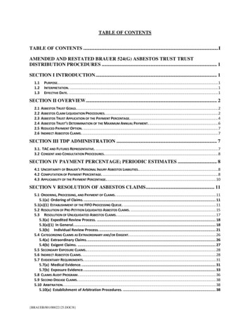
Letter 5017878 Attachment 8Table 3.II.2.3: HI-TRAC Version MS Weight and Dimension DataItemData (in inch or Commentpounds)Ref radial width of lead in the cask’s4”The data in this table corresponds toannulusthe Licensing drawing where the caskMinimum thickness of lead in the cask’s [PROPRIETARY cavity height is set by the “referencePWR fuel”. The radial thickness ofannulusINFORMATIONlead and water jacket cavity are asWITHHELD INlisted in this table. These shieldingACCORDANCEmaterial thicknesses may be adjustedWITH 10 CRto optimize shielding within the2.390]constraint of the cask laydown space inRef radial width of water jacket in the cask4 3/4”the Fuel Building and the capacity ofbodyMinimum radial width of water jacket in [PROPRIETARY the cask crane. The tornado missileanalysis in Section 3.II.4 uses thethe cask bodyINFORMATIONreference data from this table.WITHHELD INACCORDANCEWITH 10 CR2.390]Weight of empty cask with bottom lid120,000attached (empty water jacket)Weight of Water in HI-TRAC Water8,100JacketHI-TRAC weight with MPC in the pool,230,000water jacket full without accounting forbuoyancy effectsHI-TRAC weight with MPC in the pool,222,000water jacket empty without accounting forbuoyancy effectsHI-TRAC weight with “loaded, welded215,000and prepped” MPC (Includes 5% adderfor fabrication tolerances)Table 3.II.2.4: Weight Data on HI-STORM 100S Version E OverpackRef. Concrete density175 pcf225 pcfWeight of cask bodywith MPC in kips(including lid)336,100392,100Weight of top lid inkips29,00034,000CommentsThe weight datacorresponds to theLicensing drawingHOLTEC INTERNATIONAL COPYRIGHTED MATERIALHI-STORM 100 FSARProposed Rev. 17AREPORT HI-20024443.II-6
Letter 5017878 Attachment 8SUPPLEMENT 5.II: SHIELDING EVALUATION5.II.0 IntroductionThis supplement is focused on providing a shielding evaluation of the HI-STORM 100 System with thefollowing components: MPC-32 Version 1, MPC-68 Version 1, MPC-32M as well as the HI-STORM 100SVersion E storage cask and the HI-TRAC Version MS transfer cask. The evaluation is performed pursuantto the guidelines in NUREG-1536.MPC-32M is a new canister, that is the PWR counterpart of MPC-68M analyzed in Supplement 5.III. Also,slightly modified updates of the classical canisters, namely MPC-32 Version 1 and MPC-68 Version 1, areintroduced in this supplement. The evaluation presented herein supplements the evaluations in the mainbody of Chapter 5 of this FSAR, and information in the main body of Chapter 5 that remains applicable isnot repeated here. To aid the reader, the sections in this supplement are numbered in the same fashion asthe corresponding sections in the main body of this chapter, i.e., Sections 5.II.1 through 5.II.6 correspondto Sections 5.1 through 5.6. Tables and figures in this supplement are labeled sequentially.The design goal for the HI-STORM 100S Version E and HI-TRAC Version MS casks is to provide overall(not necessarily locally) the same or better performance as of the reference HI-STORM 100S Version Band 100-ton HI-TRAC casks, respectively, considering the design basis fuel loading Specifically, the designbasis burnup-cooling time combinations for uniform loading patterns in Section 5.1 as well as the designbasis loading curves (which specify burnup and cooling time combinations for all/specific cells in the cask)for the uniform, regionalized and discrete loading patterns, presented in Table 2.II.1.6 for MPC-32M, havebeen evaluated. The purpose of this supplement is simply to present the results of shielding analyses, whichconfirm that this design goal is met, hence the conclusions in the main body of this chapter remain fullyapplicable.In addition, in order to simplify a fuel qualification procedure and present reasonably bounding dose ratesfor the HI-STORM 100S Version E and HI-TRAC Version MS casks, a modified approach is used tospecify the MPC-32M basket content’s burnup, enrichment and cooling time.HOLTEC INTERNATIONAL COPYRIGHTED MATERIALHI-STORM 100 FSARProposed Rev. 17AREPORT HI-20024445.II-1
Letter 5017878 Attachment 85.II.1 Discussion and ResultsThe HI-STORM 100S Version E cask is an enhanced version of HI-STORM 100S Version B with a numberof improvements, such as a new design of the inlet and outlet vent systems, increased density of theshielding concrete in the overpack body and top lid, etc.The HI-TRAC Version MS transfer cask is anatomically similar to HI-TRAC 100 and HI-TRAC 125 caskmodels analyzed in the main part of Chapter 5 of this FSAR. It is essentially a smaller diameter version ofHI-TRAC VW Version V transfer cask in the HI-STORM FW FSAR [5.II.1]. The HI-TRAC Version MS(acronym for maximum shielding) cask is designed to provide maximum shielding to the plant personnelengaged in conducting short-term operations and facilitate ALARA transfer of a loaded MPC to or fromthe storage module. To optimize the shielding in the body of HI-TRAC Version MS, the thickness of thelead cylinder and the water jacket can be varied to meet the shielding demand of the MPCs being loaded.The HI-STORM Version E and HI-TRAC Version MS casks can accept all MPC designs, considered inthe main body of the FSAR, as well as MPC-32 Version 1, MPC-68 Version 1 and MPC-32M, introducedin this supplement. For additional details about the HI-STORM Version E and HI-TRAC Version MScasks, the reader is referred to Supplements 1.II and 2.II.The modified updates of the classical canisters, namely MPC-32 and MPC-68, are introduced with theidentifier “Version 1” appended to differentiate them from their base designs. The MPC Version 1 changesaffecting shielding are a slightly reduced basket wall thickness, increased baseplate thickness, and basketshims. The studies, described in Section 5.4, show that the self-shielding of the fuel and basket for neutronradiation is low, while for photon radiation it is very high. The low neutron self-shielding means that theneutron doses are not significantly affected by the reduced basket weight, since the majority of the neutronshielding function is provided by the overpack around the MPC. The high self-shielding for photons meansthat only the outer basket panels are effective for gamma shielding. For the MPC Version 1, the shieldingin this area is enhanced due to the presence of the basket shims, and therefore comparable to the absorptionin the thicker basket walls of the classical MPC-32 and MPC-68 baskets. The baseplate thickness increaseimpacts the fuel assembly elevation and provides better shielding performance at the bottom of theoverpack. In summary, based on the small effect of the design changes in MPC Version 1 on dose rates,those Version 1 MPCs are also qualified for all other overpacks evaluated in the main part of this chapterwithout any further analyses.MPC-32M is a variation of the 32 cell PWR canister MPC-32 evaluated in the main part of this chapter,but with a basket design consisting of aluminum oxide and finely ground boron carbide dispersed in a metalmatrix of pure aluminum. The boron carbide content is 10% (minimum) by weight. This results in a B-10areal density that is slightly above that in MPC-32. The relevant differences between the baskets are listedbelow, and then discussed in respect to its effect on the photon and neutron dose rates.Differences between MPC-32M compared to MPC-32, in respect to the characteristics important for thedose calculations, are as follows: MPC-32M has a slightly higher B-10 content;MPC-32M is lighter, since it consists of aluminum and boron carbide, but no steel;In the enclosure shell, MPC-32M is surrounded by aluminum basket shims.To evaluate the effect of these differences, studies in the main part of Chapter 5 regarding dose contributionsfrom a regionalized loading scheme are utilized. These studies, described in Section 5.4, show that theinner region of MPC-32 (12 assemblies 38 % of the content) contributes about 21% of the neutron doseHOLTEC INTERNATIONAL COPYRIGHTED MATERIALHI-STORM 100 FSARProposed Rev. 17AREPORT HI-20024445.II-2
Letter 5017878 Attachment 8rate, but only about 1 % of the photon dose rate. This means that the self-shielding of the fuel and basketfor neutron radiation is low, while for photon radiation it is very high. The low neutron self-shieldingmeans that the neutron doses are not significantly affected by the reduced basket weight, since the majorityof the neutron shielding function is provided by the overpack around the MPC. Also, for MPCs filled withwater, there is a further reduction in neutron dose due to the increased absorption of thermal neutrons fromthe increased B-10 loading. The high self-shielding for photons means that only the outer basket panels areeffective for gamma shielding. For MPC-32M, the shielding in this area is enhanced due to the presenceof the basket shims, and therefore comparable to the absorption in the steel basket walls. In summary, theeffect of the design differences between MPC-32 and MPC-32M on dose rates is small. Therefore, themain body of this chapter (including the array classes qualified for loading into MPC-32) remains fullyapplicable for the HI-STORM 100 System using an MPC-32M. Nevertheless, the shielding analyses areexplicitly performed for HI-STORM Version E with MPC-32M in this supplement and the highest doserates are reported.The shielding analyses in this supplement were performed with an updated version of MCNP(MCNP5-1.51) [5.II.2] developed by Los Alamos National Laboratory (LANL). The source terms for thedesign basis fuels were calculated using TRITON / ORIGAMI modules of the SCALE 6.2.1 code package[5.II.3] developed by Oak Ridge National Laboratory (ORNL). A detailed description of the MCNP modelsand the source term calculations are presented in Sections 5.II.3 and 5.II.2, respectively.The same design basis zircaloy clad fuel assemblies used for calculating the dose rates presented in themain body of this chapter, namely B&W 15x15 and GE 7x7 (see Section 5.2), are used in this supplementfor PWR and BWR fuel types, respectively.From a thermal perspective, the MPC-32M basket can be loaded in uniform, regionalized or discretefashion. For the uniform loading, all cells have the same heat load limit, whereas for the regionalized anddiscrete loading patterns, the heat load limits vary for different cells, according to the information in Table2.II.1.5 and Figures 2.II.1-2 and 2.II.1-3. To prescribe radiological limits for the fuel to be loaded, loadingcurves are defined in Paragraph 2.II.1.5.2, where a loading curve specifies the minimum cooling time as afunction of fuel burnup. Different loading curves are defined for the different heat load limits, so that thethermal and radiological requirements for the fuel in each cell are approximately aligned. However, itshould be noted that thermal and radiological limits for each assembly are applied completely independentfrom each other. The loading curves for the uniform, regionalized and discrete loading patterns for the fuelto be loaded in the MPC-32M canister are discussed in Subsection 5.II.2.2.[PROPRIETARY INFORMATION WITHHELD IN ACCORDANCE WITH 10 CFR 2.390]HOLTEC INTERNATIONAL COPYRIGHTED MATERIALHI-STORM 100
Each MPC, HI-STORM overpack, and HI-TRAC transfer cask shall be marked with a model number, identification number (to provide traceability back to documentation), and the empty weight of the item in accordance with the marking requirements s