Transcription
Integration NoteAutomation/Lighting esVersions:VisionTools Pro-E (for GUI). V5.5.11 or laterSIMPL Windows for processor programming).V4.02 or laterV2.00 or later (consolidated version for IP andSerial control using Telnet-Port 23).Note: UDP communication can be used usingPort 4000 and 5000 if desired but notrecommended.Crestron Dealer PortalNote: current name is Converging SystemseNode & IBT-100 ILC LED ControlJune 1, 2016Specific Profile/Driver Version:Download location for Profile/DriverDocument Revision Date:OVERVIEW AND SUPPORTED FEATURESThe CRESTRON 2-Series and 3-Series platforms support the Converging Systems’ family of motor and LEDlighting control products using either RS-232 serial connection (IBT-100) or Ethernet (e-Node).Integration with Converging Systems’ platforms is enabled from the range of CRESTRON wall pads,touchscreens and other user interfaces. Additionally, status available from a number of ConvergingSystems’ controllers can trigger commands and other events within the above lighting /automation system.For example, a motor movement can trigger a lighting event. Or a lighting command issued can signalback to the touchscreen device as to its current setting (slider movement or level setting).CURRENT DRIVER SUPPORT THE FOLLOWING FEATURESThe following commands are supported by the current driver for the various lighting and motor controldevices (except those that are grayed out).LED Lighting tion2General LED Control CommandsILC100ILC400eNode/DMX
ONOFFEFFECT,1EFFECT,n ( 1)STORE,#RECALL,#DISSOLVE.1 XXDISSOLVE.2 XXDISSOLVE.3 XXSEQRATE XXOnOffStoreRecallSet LED DissolveRateSet LED SequenceRateSUN UPSUN DOWNSUN.SHSB (HSL) Color Space CommandsFADE UPBrightness UpFADE DOWN Brightness DownSET,LBrightnessHUE UP-Hue Up and AdjustLED-Adjust LED Levelsmoves by step.HUE DOWNHue DownHUE,HHueSAT UPSat UpSAT DOWNSat DownSAT SSatSTOP?COLOR H.S. ? N/AN/A N/A N/A N/A ********* N/A N/A LPRESETH.X XXX.XXX.XXXSet LED Presets/HLSColor spacer forpreset xRGB Color Space CommandsRED,RRedGREEN,GGreenBLUE,BBlueVALUE R.G.B ?WHITE,WVALUE R,G,B,WPRESET.X XXX Set LED Presets/RGBPage 2Converging Systems Inc. 32420 Nautilus Drive Rancho Palos Verdes, CA 90275 Converging Systems Inc. All Rights Reserved. E-Node, ILC-100, IMC-100, and IBT-100 are trademarks of Converging SystemsInc. All other trademarks are the property of their respective owners
.XXX.XXX (3Color spacer forcolor)preset xPRESET.X XXX**.XXX.XXX (4color) STOP?Correlated Color Temperature (CCT) Commands CCT,XXXX CCT UP CCT DOWNBi-Directional CommandsCOLOR ?Automatic pollingwithin DriverVALUE ?Automatic pollingwithin DriverPRESETH.X ?PRESET.X ?* N/A N/A******Accessory Enode Command/Setup ParametersVerboseMode (TBD) Telnet Port 23(standard) Telnet LoginwithAuthentication (with eNode UDP Port4000/5000(optional)Telnet LoginwithoutAuthentication Notes:*When needed, these can be implemented using dealer programmed serial strings user RAW CMD. See Appendix 2 for more information.1 Note these commands can be verified within SIMPL Windows, under Project Modules/Lighting and by selecting Converging Systems ILC LED FeedbackProcessor, and selecting Edit User Module2These names can be selected or user names implemented instead.Page 3Converging Systems Inc. 32420 Nautilus Drive Rancho Palos Verdes, CA 90275 Converging Systems Inc. All Rights Reserved. E-Node, ILC-100, IMC-100, and IBT-100 are trademarks of Converging SystemsInc. All other trademarks are the property of their respective owners
Motor Commands (in S-8:Serial I/O module-future delivery file TBD)GeneralCommandsCRESTRONNamingConventionGeneral Motor Control CommandsUPDOWNSTOPRETRACTSTORE,#RECALL,#PRESET.X XX.XXIMC100BRIC(“BricMode”) Bi-Directional CommandsSTATUS ?POSITION ?Accessory Enode Command/Setup Parameters VerbosexMode Telnet LoginwithAuthentication (with eNode UDP Port4000/5000Telnet LoginwithoutAuthentication CURRENT PROFILES DO NOT SUPPORT THE FOLLOWING FEATURESOther than any features that are grayed out below, any features specified below are currentlyunsupported.Any feature not specifically notes as supported should be assumed to beunsupportedPage 4Converging Systems Inc. 32420 Nautilus Drive Rancho Palos Verdes, CA 90275 Converging Systems Inc. All Rights Reserved. E-Node, ILC-100, IMC-100, and IBT-100 are trademarks of Converging SystemsInc. All other trademarks are the property of their respective owners
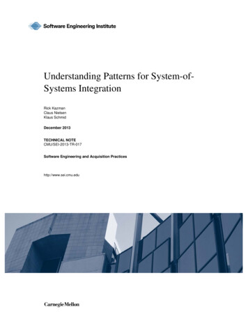
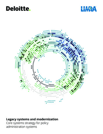
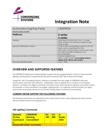
WIRING DIAGRAM (for IP connection)Figure 1Wiring/Configuration Notes:1.2.3.Maximum length of CS-Bus cabling from e-Node to the last ILC-100 using CAT5e or better cabling(and obeying the 1-1 pin-out requirements for the RJ-25-RJ25 cable) 4000 feetMaximum number of ILC-100 controllers and Converging Systems’ keypads (if provided) that canexist on a single network connected to a single e-Node device 254Maximum number of e-Nodes that can exist on a CRESTRON system 254BILL OF MATERIALS (for IP ctorType1CRESTRON 2Series and 3SeriesprocessorsNetwork ightingController (orMotorConvergingSystemsILC-100 orIMC-100 or(StewartCS-BusprotocolRJ-45RJ-45 (forEthernet)RJ-25 for localbusRJ-25 for age 5Converging Systems Inc. 32420 Nautilus Drive Rancho Palos Verdes, CA 90275 Converging Systems Inc. All Rights Reserved. E-Node, ILC-100, IMC-100, and IBT-100 are trademarks of Converging SystemsInc. All other trademarks are the property of their respective owners
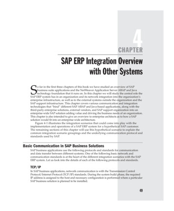
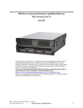
Controller)5Flexible LinearLighting (FLLA)RGB or RGBWluminariesBRIC)ConvergingSystemsand end ofbus with 120ohm resisteron pins 3/4FLLA-RGBxxxFLLA-RGBWxxx3-color 4 pin4-color 5 pin1-color 4 pinWIRING DIAGRAM (for RS-232 serial connection)Figure 2Wiring/Configuration Notes:1.2.3.Maximum length of CS-Bus cabling from e-Node to the last ILC-100 using CAT5e or better cabling(and obeying the 1-1 pin-out requirements for the RJ-25-RJ25 cable) 4000 feetMaximum number of ILC-100 controllers and Converging Systems’ keypads (if provided) that canexist on a single network connected to a single e-Node device 254Maximum number of e-Nodes that can exist on a CRESTRON system 254BILL OF MATERIALS (for RS-232c nnectorType1CRESTRON e 6Converging Systems Inc. 32420 Nautilus Drive Rancho Palos Verdes, CA 90275 Converging Systems Inc. All Rights Reserved. E-Node, ILC-100, IMC-100, and IBT-100 are trademarks of Converging SystemsInc. All other trademarks are the property of their respective owners
2series or 3seriesprocessorDB-9F to DB9M (CNSP-121)(optional if theIBT-100 is notable to beplugged intothe ntroller (orMotorController)ConvergingSystemsILC-100 orIMC-100 or(StewartBRIC)CS-Bus protocol5Flexible LinearLighting (FLLA)RGB or -xxxDB-9 (for serial)DB- DB9F9M122 Tx33 Rx455G6789DB-9 (for Serial)RJ-25 for localbusRJ-25 for CS-BuscommunicationMustterminatebeginningand end ofbus with120 ohmterminatingresister onpins 3/43-color 4 pin4-color 5 pin1-color 4 pin*Plug directly into processor or use straight DB9M to DB9F cable (item #2) between the Crestronprocessor and the IBT-100System Configuration/ProgrammingBefore proper operation between the Converging Systems’ controllers and the CRESTRON system canbegin, it will be first necessary for most applications to configure the Converging Systems’ products usingthe e-Node Pilot (PC-based) application (and the e-Node). In addition, communication parameters withinthe CRESTRON SIMPL Windows application are also required. Refer to the specified instructions below forthe particular Crestron subsystem for more information.You may wish to go the topic that is most relevant for you (click on link).SectionSubtopicsSectionStarting a new SIMPL ProjectSection 1Backgrounde-Node ProgrammingIBT-100 ProgrammingDevice ProgrammingCrestron ProgrammingPage 7Converging Systems Inc. 32420 Nautilus Drive Rancho Palos Verdes, CA 90275 Converging Systems Inc. All Rights Reserved. E-Node, ILC-100, IMC-100, and IBT-100 are trademarks of Converging SystemsInc. All other trademarks are the property of their respective owners
Importing Converging Systems(CSI) Driver into your projectSetting Up CommunicationParameters with CSI deviceAdding Tasks or Macros toButton pushesUploading Code to CrestronProcessor, Touch Panels, and XPanelsSection 2Section 3Section 4Section 5Common MistakesProgramming New StringsAppendix 1Appendix 2Advanced ProgrammingDMX Programming SupportTroubleshootingAppendix 3Appendix 4Appendix 5BackgroundThe Converging Systems e-Node is an Ethernet communication device which can be used to connect theCrestron Host to one or more Converging Systems motor and/or lighting controllers. Alternatively, theConverging Systems’ IBT-100 serial interface device can be used alternatively to connect the same numberof Converging Systems’ controllers to a Crestron processor in situations where Ethernet communication isnot desired (but where bi-directional feedback is still required).However, regardless of whether you desire to interface more than one lighting controller (or motorcontroller) each with its own controllable operation (i.e. its own Zone/Group/Node or ZGN address) witheither the e-Node (Ethernet) or the IBT-100 (RS-232c communication), and/or you desire bi-directionalcommunication/feedback between your user interface (UI) and a particular motor or lighting controller,you must still follow the directions below under (i) e-Node Programming and (ii) ILC-100/ILC-400Programming in order to establish unique ZGN address(es) for connected loads and turn on the NOTIFYcommand which provides for that bi-directional communication.Note: If you plan on utilizing the IBT-100 for serial communication and (i) you will not need more than oneaddress other than the factory default ZGN address of 2.1.0 for lighting controllers or 1.1.0 for motorcontrollers, and (ii) you do not need bi-directional communication between the lighting load or the motorload and your User Interface, then you can proceed to the IBT-100 Set up Section and you may skip the (i)e-Node Programming section as well as (ii) the ILC-100/ILC-400 Programming sections below.Settings that can be implemented using this setup are as follows:e-Node Programming/Device ProgrammingMin requirements for this operation Computer running Windows XP or later OS, preferably with a wired Ethernet connection to a localrouter using CAT5 type cablingConverging Systems E-Node Ethernet adapter, connected using CAT5 cabling to the above router.Download of the latest version of e-Node Pilot application, unzipped and operating on your computerplatformPowered up and connected ILC-x00 controller using straight thru (1-1) wiring using a 6-pin RJ-connector(Do not use 568A or 568B wiring and simply chop of the browns because this does not preserve twistedPage 8Converging Systems Inc. 32420 Nautilus Drive Rancho Palos Verdes, CA 90275 Converging Systems Inc. All Rights Reserved. E-Node, ILC-100, IMC-100, and IBT-100 are trademarks of Converging SystemsInc. All other trademarks are the property of their respective owners
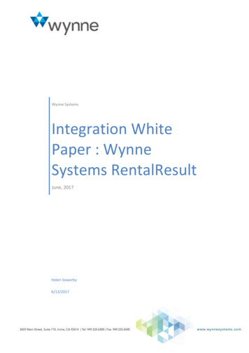
pairs on pins 1 / 2, 3 /4 , and 5/ 6 which is required).Recommended RJ-25 6P6C connections 6wirese-Node SideILC-x00Color of wiresidePin 1Pin 2Pin 3Pin 4Pin 5Pin 6Note:Pin 1Pin 2Pin 3Pin 4Pin 5Pin uboptimal RJ-11 4P4C connection 4 wirese-NodeSideILC-x00 sideColor of wirePin 1Pin 2Pin 3Pin 4Pin 1Pin 2Pin 3Pin 4OrangeBlueBlue/whiteOrange/whiteFor the purposes of commissioning if you do not have 6P6C RJ-25 connectors, you can usestandard 4-pin RJ11 connectors, but follow the wiring directions above preserving twisted pairson Pin 2/3 and Pins 1 /4. This cable will not work for keypad communication or IBT-100communication.Please follow the below steps under “e-Node Programming” when using the e-Node for Ethernetcommunication or to set-up specific loads (lighting or motor) with unique, non-zero, Zone/Group/Node orZGN addresses.e-Node ProgrammingStep SettingChoicesEN-1e-Node IP AddresssettingStatic or Dynamic AddressingSet up the e-node withan appropriate Staticor Dynamic IP address.Refer to the separate“e-Node Quick StartGuide” on how tomake such settings.-Launch the e-Node Pilot application.-Select the View e-Node tab and select the Discover e-Node button.Any e-Node(s) connected on the same network will appear as shown.Page 9Converging Systems Inc. 32420 Nautilus Drive Rancho Palos Verdes, CA 90275 Converging Systems Inc. All Rights Reserved. E-Node, ILC-100, IMC-100, and IBT-100 are trademarks of Converging SystemsInc. All other trademarks are the property of their respective owners
-Select the mark in front of the e-Node found to expand the menu.-Review the DHCP entry, the factory default is ENABLE which meansDHCP is activated. DISABLE for DHCP refers to static IP addressing. If youwish to set a STATIC IP address, enter the following variables in the orderspecified below:STATIC IPxxx.xxx.xxx.xxxYour new static IPaddressGATEWAY ADDxxx.xxx.xxx.xxxTypically the addressof your network’sgatewayFINALLY and onlyAnd Set to DISABLENow reboot the eafter you have setNode for this to takethe above variables,effect.select DHCPEN-2TELNET Port (transmitand receive)Note: Communicationto the e-Node is alsopossible using UDP(Port xxx for Sendingfrom Crestron and Portxxx for Receiving fromCrestron). You maywish to select UDP is-Note: It is recommended that only STATIC addressing be used with theCRESTRON processors.Depending upon the functionality of the CRESTRON driver and theinstaller’s specific settings, the suggested communication protocolbetween Crestron the e-node is Telnet Port 23 communication (with oror without Login). You will need at minimum (i) to turn on Telnet withinthe e-Node, and (ii) to adjust secondarily the setting for Login asrequired by the CRESTRON driver.1) Select the View e-Node tab and select the Telnet tab. Set SERVER toENABLE.2) Login Settings.Page 10Converging Systems Inc. 32420 Nautilus Drive Rancho Palos Verdes, CA 90275 Converging Systems Inc. All Rights Reserved. E-Node, ILC-100, IMC-100, and IBT-100 are trademarks of Converging SystemsInc. All other trademarks are the property of their respective owners
the single TELNETSERVER port within thee-Node is being usedfor alternativepurposes (anothercontrol system).EN-3Notify Modea) If Telnet communication with Login is supported, set LOGIN toENABLE and select the Restart button for the particular e-Node thatyou are utilizing to communicate with the CRESTRON system.b) If Telnet communication with Login is unsupported, set LOGIN toDISABLE and select the Restart button for the particular e-Node thatyou are utilizing to communicate with the CRESTRON system.The CRESTRON software is able to intelligently poll the ConvergingSystem’s Intelligent Lighting Controllers (either through the e-Node IPdevice or the IBT-100 serial device). That polling frequency is set withinthe Crestron driver. Alternatively, Converging Systems’ has an autonotify facility which is able to transmit status messages only after a statechange, in HSB/HSL mode, RGB mode or both. Depending upon yourparticular needs, you may wish to silence the e-Node’s NOTIFY logic inorder to reduce bus traffic. However, by enabling the NOTIFY logic,greater responsiveness is assured to CRESTRON sliders.Within the e-Node Pilot application, select each controller (i.e. ILCLighting Controller) that you wish to adjust from the View Map tab. Thenopen the LED tab. Find the NOTIFY variable, and set it to OFF. This willprevent the selected controller from broadcasting its status after everystate change therefore reducing CS-Bus traffic.Page 11Converging Systems Inc. 32420 Nautilus Drive Rancho Palos Verdes, CA 90275 Converging Systems Inc. All Rights Reserved. E-Node, ILC-100, IMC-100, and IBT-100 are trademarks of Converging SystemsInc. All other trademarks are the property of their respective owners
IBT-100 ProgrammingAll of the communication parameters to support the IBT-100 are built into the Crestron IBT-100 driver andtherefore no special programming is required of the IBT-100 serial adapter. However, certain features of theILC-100/ILC-400 with respect to NOTIFY (which permits automatic signaling of color status upon color statechanges) described above will need to be programmed using the e-Node. But in this case, after thespecific lighting controllers are programmed, the e-Node will no longer be required for Crestron toConverging Systems communication using the IBT-100.RS-232C Interfacing Note:If you plan on simply using the IBT-100 for serial communication anddesire to have multiple lighting loads (more than one ILC-100 with a unique Zone/Group/Node address youmust set up your system using the e-Node as specified above as well as the particular lighting load asspecified below. However, if you do not care about bi-directional feedback or support of multiplecontrollers address, no further set-up is required. However, this is not recommended.ILC-100/ILC-400 ProgrammingStepDV-1SettingILC-x00 Discovery and AddressSetupChoicesMore thorough documentation of this step can be found inthe e-Node Commissioning Guide referenced in Step EN-1above. However for document completeness, an abridgeversion of this guide is summarized below.Background. From the factory the ILC-x00 controllers do nothave an assigned UID (unique ID) address. Units comeequipped with a factory default address of Zone 2, Group 1,and Node undefined or a 0. If you set up your CRESTRONsystem to communicate with an ILC-x00 with an address of2,1,0 the ILC-x00 will react but it will not provide feedbackdata which is required for automatic slider updates within theCRESTRON systems. Therefore, it is advisable to set up a nonzero address for each ILC-x00 controller that is connected toPage 12Converging Systems Inc. 32420 Nautilus Drive Rancho Palos Verdes, CA 90275 Converging Systems Inc. All Rights Reserved. E-Node, ILC-100, IMC-100, and IBT-100 are trademarks of Converging SystemsInc. All other trademarks are the property of their respective owners
either an IBT-100 or an e-Node. The directions below indicatedhow to perform this operation. (See Step 2b below for moreinformation on Zone/Group/Node addressing.)For newer versions of the e-Node/MKIII, the process todiscovery devices has become more streamlined. Refer to theappropriate section below for your specific version of e-Node.Note: e-Node MKIII has 2 RJ-25 ports and 1 RJ-45 port on thecommunication side of the controller while the MKII versionhas just 2 RJ-25 portsMKIII e-Nodes utilizing new SN discoveryProcess.(1) Power on the e-Node and any connected ILC-x00controllers.(2) Launch the Pilot application and select the Discover eNode within the View Map tab.(3) Next select the Devices button and all compatible ILC-x00controllers will instantly appear with their SN under thepreviously discovered E-Node.(4) Next, (i) assign an unused UID (unique ID) to the ILC device to beaddressed (generally start with the UID value of “1” and work upsequentially) and enter this number into the UID window, then (ii)highlight the e-Node to which the device is connected, then (iii)select the device with SN displayed and then (iv) select “SET.” Theinitial ILC device with a SN “name” will be updated to a programmedUID n entry.Note: If your device does not have SN Addressing, proceed to thestandard UID Discovery process detailed und
SIMPL Windows for processor programming). V4.02 or later Specific Profile/Driver Version: V2.00 or later (consolidated version for IP and Serial control using Telnet-Port 23). Note: UDP communication can be used using Port 4000 and 5000 if desired but not recommended. Download location f