Transcription
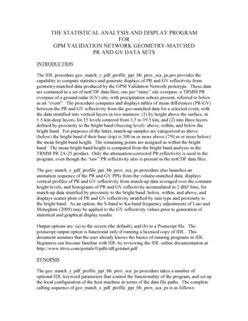
THE STATISTICAL ANALYSIS AND DISPLAY PROGRAMFORGPM VALIDATION NETWORK GEOMETRY-MATCHEDPR AND GV DATA SETSINTRODUCTIONThe IDL procedure geo match z pdf profile ppi bb prox sca ps.pro provides thecapability to compute statistics and generate displays of PR and GV reflectivity fromgeometry-matched data produced by the GPM Validation Network prototype. These dataare contained in a set of netCDF data files, one per “rainy” site overpass: a TRMM PRoverpass of a ground radar (GV) site, with precipitation echoes present, referred to belowas an “event”. The procedure computes and displays tables of mean differences (PR-GV)between the PR and GV reflectivity from the geo-matched data for a selected event, withthe data stratified into vertical layers in two manners: (1) by height above the surface, in1.5-km-deep layers, for 15 levels centered from 1.5 to 19.5 km, and (2) into three layersdefined by proximity to the bright band (freezing level): above, within, and below thebright band. For purposes of the latter, match-up samples are categorized as above(below) the bright band if their base (top) is 500 m or more above (750 m or more below)the mean bright band height. The remaining points are assigned as within the brightband. The mean bright band height is computed from the bright band analysis in theTRMM PR 2A-25 product. Only the attenuation-corrected PR reflectivity is used in theprogram, even though the “raw” PR reflectivity also is present in the netCDF data files.The geo match z pdf profile ppi bb prox sca ps procedure also launches ananimation sequence of the PR and GV PPIs from the volume-matched data; displaysvertical profiles of PR and GV reflectivity from match-up data averaged over the constantheight levels, and histograms of PR and GV reflectivity accumulated in 2 dBZ bins, formatch-up data stratified by proximity to the bright band: below, within, and above; anddisplays scatter plots of PR and GV reflectivity stratified by rain type and proximity tothe bright band. As an option, the S-band to Ku-band frequency adjustments of Liao andMeneghini (2009) may be applied to the GV reflectivity values prior to generation ofstatistical and graphical display results.Output options are: (a) to the screen (the default), and (b) to a Postscript file. Thepostscript output option is functional only if running a licensed copy of IDL. Thisdocument assumes that the user already knows the basics of running programs in IDL.Beginners can become familiar with IDL by reviewing the IDL online documentation t.pdf.SYNOPSISThe geo match z pdf profile ppi bb prox sca ps procedure takes a number ofoptional IDL keyword parameters that control the functionality of the program, and set upthe local configuration of the host machine in terms of the data file paths. The completecalling sequence of geo match z pdf profile ppi bb prox sca ps is as follows:
geo match z pdf profile ppi bb prox sca ps, SPEED looprate,ELEVS2SHOW elevs2show, NCPATH ncpath, SITE sitefilter,NO PROMPT no prompt, PPI VERTICAL ppi vertical,PPI SIZE ppi size, PCT ABV THRESH pctAbvThresh,SHOW THRESH PPI show thresh ppi, GV CONVECTIVE gv convective,GV STRATIFORM gv stratiform, HISTO WIDTH histo Width,HIDE TOTALS hide totals, PS DIR ps dir, B W b w, S2KU s2ku Note that each keyword parameter is optional, and has a default value/behavior if leftunspecified. The use of each keyword parameter is as follows:SPEED: initial animation rate for the PPI animation loop on startup. Defaults to 3 ifunspecified or value is outside of the allowed range of 0-100.ELEVS2SHOW: number of PPIs to display in the PPI image animation, starting at aspecified elevation angle in the volume, in the form 'N.s', where N is the number of PPIsto show, and s is the starting sweep (1-based, where 1 first). Disables PPI plot ifN 0, and displays a static plot if N 1. Defaults to N 7.1 if unspecified. If s is zeroor if only N is specified, then s 1.NCPATH: local directory path to the geo match netCDF files' location. Defaults to/data/netcdf/geo match if not specified. This parameter MUST be specified if thenetCDF files are not located under /data/netcdf/geo match on the local host.SITE: file pattern, which acts as a filter limiting the set of input files shown in the FileSelector (Fig. 1), or over which the program will iterate. Mode of selecting the (next) filedepends on the NO PROMPT parameter. Default * (all files)NO PROMPT: method by which the next file in the set of files defined by NCPATHand SITE is selected. Binary parameter (e.g., /NO PROMPT or NO PROMPT 1 to setto On). If unset or set to 0, defaults to using DialogPickfile (IDL’s pop-up File Selector,shown in Figure 1). If set to On, then the program will automatically process each file inthe set, in order of ascending site ID and date.PPI VERTICAL: controls orientation for PPI plot/animation subpanels. Binaryparameter. If unset, or if SHOW THRESH PPI is On, then defaults to horizontal (PRPPI to left of GV PPI [Fig. 2]). If set, then PR is plotted above GV (Fig. 5)PPI SIZE: size in pixels of each subpanel in PPI plot. Default 375PCT ABV THRESH: constraint on the percent of full-resolution PR and GV binsaveraged into the geometric-matching volumes at or above their respective dBZthresholds, specified at the time the geo-match dataset was created (18.0 dBZ for PR,15.0 dBZ for GV). It is essentially a measure of "beam-filling goodness". 100 means useonly those matchup points where all the PR and GV bins in the volume averages were2
above threshold (the volumes are completely filled with above-threshold bin values). 0means use all matchup points available, with no regard for thresholds (the default, if nopctAbvThresh value is specified).SHOW THRESH PPI: Binary parameter, controls whether to create and display a 2ndset of PPIs plotting only those PR and GR points meeting the PCT ABV THRESHconstraint. If set to On, then PPI VERTICAL defaults to horizontal (PR left of GV)GV CONVECTIVE: GV reflectivity threshold at/above which GV data are consideredto be of Convective Rain Type. Default 35.0 if not specified. If set to 0, then GVreflectivity is ignored in evaluating whether PR indication of Stratiform Rain Type is amismatch to a GV indication of Convective rain type.GV STRATIFORM: GV reflectivity threshold at/below which GV data are consideredto be of Stratiform Rain Type. Default 25.0 if not specified. If set to 0, then GVreflectivity is ignored in evaluating whether a PR indication of Convective Rain Type is amismatch to a GV indication of Stratiform rain type.HISTO WIDTH: Bin size to be used in generating histogram totals for the reflectivityhistogram plots. Default 2.0 (dBZ)HIDE TOTALS: Binary parameter, controls whether to show (default) or hide thehistogram and vertical profile plots for rain type "Any".PS DIR: Directory to which postscript output will be written. If not specified or set to“Off”, output is directed only to the screen.B W: Binary parameter, controls whether to draw vertical profile and histogram plots inPostscript file in color (default) or in black-and-white.S2KU: Binary parameter, controls whether or not to apply the Liao/Meneghini S-band toKu-band frequency adjustment GV reflectivity. Default noRUNNING THE PROGRAM (IDL License Available)The following instructions apply to running the statistical analysis procedure with alicensed copy of IDL, or without an unlicensed copy, in time-limited evaluation mode.See the IDL Virtual Machine Option section for instructions on running the procedurewith the IDL Virtual Machine.The geo match z pdf profile ppi bb prox sca ps procedure is provided as aprecompiled and saved IDL binary file:geo match z pdf profile ppi bb prox sca ps.sav. To run the file, place it in adirectory of your choice, and start IDL (either command-line mode or DevelopmentEnvironment [IDLDE]). At the IDL prompt (e.g., IDL ), change the current directory to3
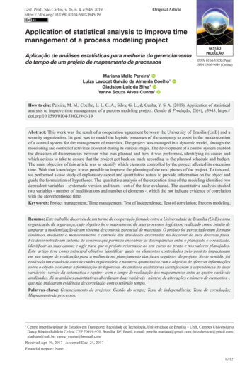
the one where the geo match z pdf profile ppi bb prox sca ps.sav file is located(the quotes in the example commands are required):IDL cd, ‘/Users/Chuck/IDL Save Files’Then ‘restore’ the saved binary procedure so that it can be run:IDL restore, ‘geo match z pdf profile ppi bb prox sca ps.sav’The procedure can then be run. At a minimum, the NCPATH parameter will need to bespecified on the command line so that the geo match netCDF file path is set. Forinstance, if the netCDF files are located under /Users/Chuck/data/netcdf/geo match, thenrun the procedure with NCPATH set as follows:IDL geo match z pdf profile ppi bb prox sca ps, NCPATH ’/Users/Chuck/data/netcdf/geo match’The is a continuation character in IDL and allows you to enter a single command overseveral lines, for readability.If all is well the procedure should then start and the file selector user interface shouldappear and be populated with the list of geo match netCDF files, as shown in Fig. 1.Figure 1. File selector for geometry-matched netCDF files.Once a file has been selected from the list in the File Selector, diagnostic and statisticaloutput from the procedure (Exhibit 1) will be listed in the terminal window (IDLcommand-line mode) or the IDLDE Console; an animation loop of PPI images of the PRand GV volume-matched data in the netCDF file will be displayed in one new window(e.g., Fig. 2); a four-panel plot with the vertical profile of reflectivity and histograms ofreflectivity above, within, and blow the bright band will be displayed in a second window(e.g., Fig. 3); and scatter plots of PR and GV reflectivity will be displayed in a third4
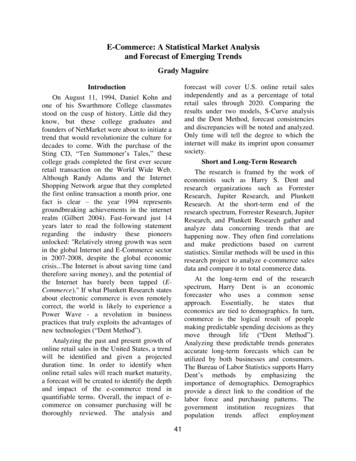
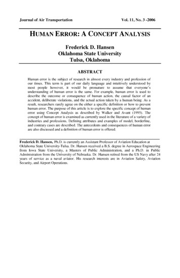
window (e.g., Fig. 4). Figure 2 shows one frame of the PPI animation. If theELEVS2SHOW parameter is unspecified, then the elevation angles to be plotted in thePPIs will be the first seven elevation sweeps in the list of elevations in the GV volumescan. Otherwise, if ELEVS2SHOW N.s is specified as a keyword parameter, then ‘N’number of sweeps in the GV volume scan will be shown in the PPI animation, beginningfrom the elevation number ‘s’, where s 1,2, nsweeps, and ‘nsweeps’ is the number ofsweeps in the volume scan. See the description of the ELEVS2SHOW parameter forother rules governing the N.s value.Note that areas indicated as Stratiform rain type are shown on the PPIs with ahorizontally-oriented line pattern, and areas of Convective rain type are shown with avertical line pattern. Samples where the rain type is Unknown or Other are plotted withsolid fill. Samples where a pattern appears on the dark gray background indicate a PRray position where no valid reflectivity value is present at the elevation being displayed.Figure 2. The PPI animation window of the statistical analysis tool, showing one frame of theanimation. Case shown is with all display parameters using their default values.If run as above with no other keyword parameters specified, the keyword parameters willtake on their default values as described in the SYNOPSIS section, above. The procedurewill produce diagnostic and statistical output in the terminal window from which IDL isrun, or in the console window of IDLDE. Shown below in Exhibit 1 is the IDL output forthe default case where no parameters other than NCPATH are specified, for the caseshown in Fig. 2.Figure 3 shows the on-screen output window containing the vertical profiles andhistograms of PR and GV reflectivity. Separate profiles and histograms are shown fordata points having rain types of convective, stratiform, and Any rain type (labeled All orAny/All), for both the PR and GV radars. By default, the Total rain type profiles andhistograms are included in the plots. These may be excluded from the plots for clarity bysetting the HIDE TOTALS binary keyword parameter to “ON”. Also, the width of thebins in which the reflectivity histograms are totaled is set to 2 dBZ by default. This valuemay be adjusted by specifying a different value for the HISTO WIDTH keyword5
parameter. A value of 1 results in the most detail in the histogram plots, but can be verynoisy and jagged. A smoother plot results from raising the value of HISTO WIDTH. Bydefault, and for all output to the screen, the PR profiles and histograms are shown in redand the GV in green. For Postscript output only, black-and-white vertical profile andhistogram plots result if the B W binary keyword parameter is set to “ON”.The PCT ABV THRESH keyword parameter permits the analyst to constrain thevolume-match data included in the displays and calculations to only those samples wherethe specified percentage of original PR and GV bins in their respective volume averageshad reflectivity values exceeding fixed cutoff thresholds: 18.0 dBZ for the PR, and 15.0dBZ for the GV radar. Application of this data percentage threshold is an attempt to limitthe comparisons to points where partial beam filling of the sample volumes is not anissue. Each matchup point is an average of the full-resolution radar bins within the 3-Dvolume defined by the geometric intersection of a PR ray and a GV elevation sweep.Each PR and GV matchup point carries a value indicating the number of full-resolutionradar bins included in the volume average from a geometric standpoint (n pr expectedfor PR, n gv expected for GV), and another value that indicates the number of “rejected”bins (n 2a25 rejected for PR, n gv rejected for GV) within the 3-D volume whosereflectivity values are below the fixed thresholds. For a given PCT ABV THRESHparameter value, points where the following two criteria are met will be included:100*( n pr expected - n 2a25 rejected) / n pr expected PCT ABV THRESH100*( n gv expected - n gv rejected) / n gv expected PCT ABV THRESHIn the example output shown Exhibit 1, the PCT ABV THRESH parameter uses itsdefault value of zero, indicating that all matchup points with a valid reflectivity value arebeing included in the plots and statistics calculations. The default value of zero includesall points with a valid reflectivity value, regardless of the percentage of bins that areabove the cutoff thresholds. A value of 100 means to include only points where every PRand GV bin included in their respective volume averages are above the cutoff thresholds(i.e., n 2a25 rejected and n gv rejected values are both zero for the point).Each matchup point has an associated Rain Type value taken from the PR 2A-23 product,but no GV-derived rain type is present in the matchup data files. An implied, GV-basedrain type value may be derived based on GV reflectivity thresholds specified by theparameters GV CONVECTIVE and GV STRATIFORM. The default, if parametervalues disabling GV CONVECTIVE and GV STRATIFORM are not specified, is tooverride the PR rain type value for any point where the GV-implied rain type (based onapplying the GV CONVECTIVE and/or GV STRATIFORM reflectivity thresholds)differs from the PR-indicated rain type. Points whose rain type values are overridden aremoved from the Convective or Stratiform category to the Any/All rain type category, alsocalled Other. See the SYNOPSIS section for the rules describing how the overrides areapplied and/or disabled. A summary of the GV rain type reflectivity thresholds, and thenumber and type of points whose PR-indicated rain type values were overridden isincluded in the diagnostic output of the procedure, as shown in Exhibit 1.6
IDL geo match z pdf profile ppi bb prox sca ps, ncpath '/Users/Chuck/data/netcdf/geo match'Defaulting to 7 for the number of PPI levels to plot, starting with the first.Defaulting to * for file pattern.Defaulting to 375 for PPI size.Defaulting to 2.0 (dBZ) for PDF Histogram bins.Defaulting to 0 for PERCENT BINS ABOVE THRESHOLD.Defaulting to 35.0 dBZ for GV Convective floor threshold.Defaulting to 25.0 dBZ for GV Stratiform ceiling threshold.Defaulting to screen output for scatter plot.tEmP FiLe.GRtoPR.KAMX.060808.49749.ncNo. of footprints switched from Convective to Other 5, based on Stratiform dBZ threshold 25.0No. of footprints switched from Stratiform to Other 174, based on Convective dBZ threshold 35.0Mean BB (km), bblo, bbhi 5.163004.500006.00000Using histogram bin size 2.00000PR-GV Reflectivity difference statistics (dBZ) - GV Site: KAMXOrbit: 49749PR time 2006-08-08 20:04:36GV start time 2006-08-08 20:06:46Required percent of above-threshold PR and GV bins in matched volumes 0%Statistics grouped by fixed height levels (km):Vert. Any Rain Type Stratiform ConvectiveLayer PR-GVNumPts PR-GVNumPts PR-GVNumPts----- ------------ ------------ 212.06.15846.76425.5002No above-threshold points at height 13.500No above-threshold points at height 15.000No points at height 16.500No points at height 18.000No points at height 19.500% LOADCT: Loading table GRN-RED-BLU-WHT Dataset Statistics AvgDistPR MaxZGV MaxZ BB? ------------------- --- .498 @ BB67.04843.18749.165 @ 27.83449.94119.76417.080Statistics grouped by proximity to Bright Band:Proxim. Any Rain Type Stratiform Convectiveto BB PR-GVNumPts PR-GVNumPts PR-GVNumPts----- ------------ ------------ 28114% LOADCT: Loading table Blue-Red Dataset Statistics AvgDistPR MaxZGV MaxZ BB? ------------------- --- 52.16250.96950.60167.45449.43649.165 @ BB63.68041.77942.555Click END ANIMATION button or close Animation window to proceed to next case:Exhibit 1. Output diagnostics and statistics from the geo match z pdf profile ppi bb prox sca ps procedure, sent to theterminal or IDLDE console. Statistics are for the case shown in Fig. 2, using default program parameters.7
Figure 3. Vertical profiles and histograms of PR (in red) and GV (in green) reflectivity, forConvective (heavy dashed), Stratiform (dotted) and Any (solid) rain type, for the same case shown inFig. 2, with all statistical parameters using default values.8
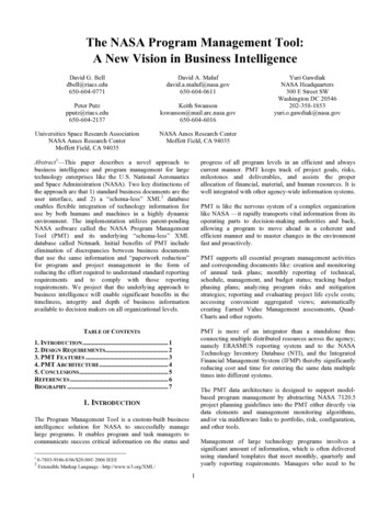
Figure 4 shows scatter plots of PR vs. GV reflectivity for all combinations of the threebright band proximity levels (above, within, below) and the two rain types (stratiform andconvective), for same case as shown in Figs. 2 and 3, and using the parameter defaults.Figure 4. Scatter plots of PR vs. GV reflectivity using default parameters, for the same case as inFigs. 2 and 3. Solid line is PR GV; dashed lines are for PR /- 3 dBZ from GV; dotted line is thelinear fit to the data.9
OPTIONAL KEYWORDSTwo types of IDL keyword parameters are used in the procedure. The regular keywordparameters take specific numerical or text string values as the parameter value, in theformat KEYWORD value, and are listed on the command line following the name of theprocedure, each separated by a comma. For those regular keywords whose values arestrings, the string value must be enclosed in quotes, e.g.,NCPATH ’/data/netcdf/geo match’. For those regular keywords whose values arenumbers, the keyword values do not need to be in quotes, e.g., ELEVS2SHOW 6.3.Binary keywords may be specified on the command line in either the KEYWORD valueformat, or in the “slash” format: /KEYWORD. In the KEYWORD value format, theoption is turned “On” be specifying a numerical value of 1 (one) for the value (e.g.,B W 1), and “Off” by specifying a value of 0 (zero) for the value (e.g., B W 0).Specifying the keyword name preceded by a slash (/) is equivalent to specifying a valueof 1 to turn the option “On”. For example, B W 1 and /B W are equivalent. If a binarykeyword is not specified on the command line, it is “Off” by default.File Selection OptionsSelection of matchup netCDF files is controlled by the NCPATH, SITE, andNO PROMPT keywords. NCPATH is used to specify a director
RUNNING THE PROGRAM (IDL License Available) The following instructions apply to running the statistical analysis procedure with a licensed copy of IDL, or without an unlicensed copy, in time-limited evaluation mode. See the IDL Virtual Machine Option section for instructions on running the