Transcription
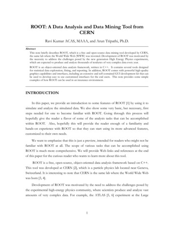
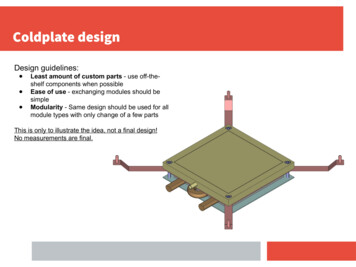
Coldplate designDesign guidelines: Least amount of custom parts - use off-theshelf components when possibleEase of use - exchanging modules should besimpleModularity - Same design should be used for allmodule types with only change of a few partsThis is only to illustrate the idea, not a final design!No measurements are final.
Metal base- No requirements
Liquid cooled coldplate- E.g. Ohmite CP4A-114C-108E- Roughly 10x10 cm cooled area
Peltier elements- E.g. TE-71-1.4-2.5- 4 elements in parallel- Elements are glued to cold plate withthermal conductive epoxy- E.g. Masterbond EP3HTS-LO
Copper vacuum chuck- Copper: low thermal resistance to peltier elements- Vacuum suction ensures homogenous and excellentthermal contact between module and chuck.- Have not found any suppliers yet, still inquiring!
Module frame holders- Module-specific holders- Consists of arms with dowels- Module handling frame slides onto dowelsfor repeatable alignment of module
Insulation suggestion: Vacuum platesPositives: 10x better (!) insulating properties than Thermaflex Impervious to humidity Comes in many sizes and thicknesses Rated for our thermal range Mass produced for building construction - cheap Rigid, not flexibleNegatives: Insulation properties are lost if outer metal foil isbrokenHeat loss through box can be made negligible with the useof vacuum plates. See calculations on following slides.Fragility of vacuum plates can be mitigated by coveringvacuum plates in thin layer of solid insulator.
New heat loss calculation
Keep the modules at -50 degrees Old heat loss calculation: Estimated total heat loss of 170W Only looking at conductive heat transfer Power consumption of modules New heat loss calculation: Overall heat transfer (convection andconduction) (Power consumption of modulesand Peltier elements) Included heat loss from tubes Included heat loss from wires Calculations on nitrogen (negligible) Compared two systems1) Original setup: Armaflex2) Vacuum setup: Vacuum plates and thin layer of armaflex32 mm32 mm10 mm32 mm40 mm
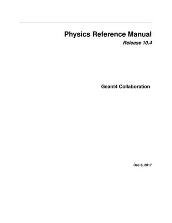
Overall heat transferSeparates into two steady state calculations21. Calculate the heat loss from the floor1Chiller plate will cool the floor insulationmaterialApproximation That whole uppersurface of the floor -25 C (Reality:Temperature gradient)2. Calculate the cooling to air and theheat loss of airAir will get cooled by the cold floorsurface, the chiller plate and thevacuum copper plateThe air will get heated by the sidesurfaces and top surface of the box12
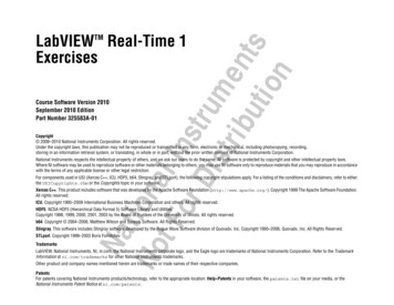
Floor conductive calculationVacuum setupArea0.4896 m2Th20 CTc-25 CL10.010 mk10.034 W/mkL20.040 mk20.0035 W/mkPfloor (vacuum)P floor (original)1.88 W23.409 WTc-25 CL1, K1, AL2,K2, A20 C
Air systemVacuum setup0.4896m2Area top0.4896m2Area sides0.48m2Area of 9 chiller plates0.0576m2Area of 9 copper plate0.1152m2αair (Heat transfer coefficient)5 W/m2K (10)Tair?Th20 CTc-25 CL10.010 mk10.034 W/mkL20.040 mK20.0035 W/mkPair (vacuum)21.42 WPair (original)29.28 W32 mm, K2, AtopL2,K2, A20 CAir temperatureL1, K1, AsideCooling of air-50 C-25 C-25 CTcArea floor
CalculationsFor original setup
Total passive heat lossCurrently upper limitsP (Vacuum box)23.3 WP (Original box)52.7 WP (tubes)60 WP (wires)10 WPTOT (Vacuum)93.3 WPTOT (Original)122.7 W The box floor temperature must be multiplied by a factor 0.3 k 1 Other simplifications (Air flow from nitrogen) Could get more accurate and flexible calculationswith simulations (ANASYS / calculation-script)
Heat loss and required cooling capacityWe wish to take the modules to -50C. We need an idea of the required cooling capacity by the externalchiller at this temperature.External chiller must compete against two sources of heat:Power dissipation in modules and peltier elements.Absorption of heat through insulation, e.g. box walls, tubing insulation, electrical cables.Cold loss via heat absorption through insulation depends primarily on temperature of cooling liquidWe can reduce cold loss by increasing the liquid temperatureThe ITK modules are cooled further down with Peltier elementsFactors to consider:Peltier element heat dissipation increases as hot-cold delta T increasesChiller cooling capacity increases as liquid temperature increasesHeat absorption decreases as liquid temperature increases There should be a liquid T “sweet spot” where the greatest possible cooling capacity is reached!
Heat loss and required cooling capacityPeltierelementsGenerates a T difference:ΔTPeltier -55C - TplateITK moduleTmodule Tchuck 5CVacuumchuckTchuck Tplate ΔTPeltierTliquidCoolingplateTplate Tliquid
Heat loss and required cooling capacityHeat absorption (“Cold loss”)through:- Coldbox insulation- Tubes between chiller/box- Electrical cables exiting boxTplateAssuming:- 3m Julabo triple insulatedtubing- Vacuum plate box insulation- Electrical cables loss is upperlimit (10W @ T -25C)- Box size 110cm x 56cm x 20cmplate
Heat loss and required cooling capacityITK modules power dissipation isconstant regardless of coolingplate temperature.10W per module x 9 modules 90W
Heat loss and required cooling capacityFor each cooling platetemperature, an optimal Peltierelement exists.- Minimum power draw- Meets heat load requirementsUsed TE’s Peltier calculator.Assuming:- Four peltier elements inparallel per moduleObservation:Peltier module heat dissipationsurpasses cooling requirements ofrest of system at Tplate -30C.
Heat loss and required cooling capacityWe (Bergen) already have aJulabo DD-1000F recirculatingchiller.Cooling capacity is lower thanrequirement for all cooling platetemperatures.Tmodule -50C can not be reached.DD-1000F
Heat loss and required cooling capacityAdding a second smaller chillerbrings the total cooling capacityabove the requirements.Other institutions can use thisapproach or purchase a singlechiller with sufficient coolingcapacity. DD-1000FCD-600F
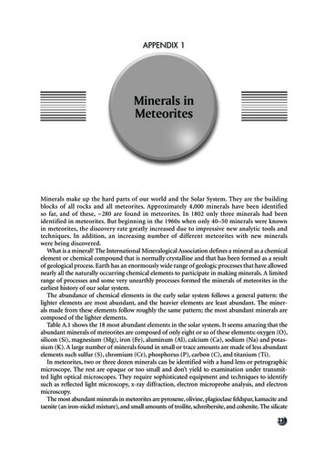
Heat loss and required cooling capacityCooling budget is greatest at Tplate -15C.Cooling capability is 213W greater thanrequirement.We will be able to reach Tmodule -50C.The time this will take from room T dependson the slope K/min and has to be calculated.
SUMMARY We have calculated upper limits on passive cold loss. Cold loss from the box can be made negligible by usingvacuum insulation plates. The optimal cold-plate temperature is -15C when using theDyneo DD-1000F and Curio CD-600F chillers and 4 TE-711.4-2.5 Peltier elements per module.213 W of additional cooling capacity will allow us to take ITKmodules to -50C even if there are unforeseen heat sourcesor inefficiencies.Heat sourceHeating power @Tplate -15CChiller liquid tubes45WBox insulation18WElectrical cables8WITK modules90WPeltier modules525WSUM687WChiller capacityBudget900W213 W
Old heat loss calculation: . Chiller plate will cool the floor insulation material Approximation That whole upper surface of the floor -25 C (Reality: Temperature gradient) 2. Calculate the cooling to air and the heat loss of air Air will get cooled by the cold floor surface, the chiller plate and the vacuum copper plate The air will get heated by the side surfaces and top surface of .