Transcription
The following article was published in ASHRAE Journal, February 2002.Copyright 2002 American Society of Heating, Refrigerating and AirConditioning Engineers, Inc.This posting is by permission of ASHRAE, and is presented for educationalpurposes only. ASHRAE does not endorse or recommend commercialproducts or services.This article may not be copied and/or distributed electronically or in paperform without permission of ASHRAE. Contact ASHRAE at www.ashrae.org.
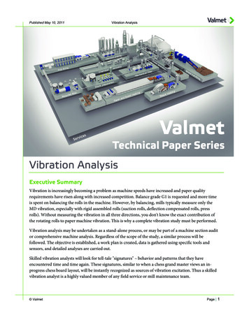
Application FundamentalsOf Ice-Based Thermal StorageBy Brian Silvetti, P.E., Member ASHRAEAs might be expected, the recent turmoil in the electric power industry has focused considerable attention on thermal storage technologies. Commercial cooling is a major contributor to peak powerdemand, but it also represents one of the few areas where load management methods are practical, cost-effective and proven. A well designed thermal storage system will effectively and efficiently reduceelectrical demand, exploit time-of-day rates and remain totally transparent to a building s occupants.Although there is considerable variety in the types of available storageequipment, the majority of today’s systems are chiller-based. In the case of icestorage systems, the chiller’s secondarycoolant is usually a 25% to 30% ethylene glycol/water solution. The coolantcirculates through a heat exchanger thatis submerged in a tank of water orthrough a tank packed with water filledcontainers.In an “internal melt” system, the secondary coolant is used to both freeze(charge) and melt (discharge) the storage material (water). The water that is frozen never leaves the storage tank. In “external melt” equipment, the glycol coolant freezes the storage material, but unfrozen water surrounding the ice is usedfor discharge.While most of this article is directedtowards the design of internal melt systems, many of the principles are applicableto other types of storage equipment.For a more complete and comprehensive discussion of different storage typesand application techniques, the reader isreferred to ASHRAE’s Design Guide forCool Thermal Storage.1Component SizingWhile any portion of the cooling loadcan be served by thermal storage, thedesigner will typically be influenced byeconomic and practical factors thatbound reasonable selection ranges.What return on investment is acceptable to the customer? Are incentives orrebates available? Are there space or accessibility limitations? How is the utility rate structured? What are the occupancy and use characteristics of the application? What are the life-cycle costsof the equipment and the influences ofseasonal changes and climate? Will operating or maintenance costs be a factor?Figure 1 represents four different approaches to the same design day coolingload profile.Our example building has a peak loadof 1 ton (3.5 kW) with a total coolingrequirement of 9.5 ton (33 kW) hours inReprinted by permissiona 12-hour cooling period. Consequently,chiller and storage requirements are presented on a “per ton of peak load” basis.In a thermal storage system the building peak load (tons) no longer definesthe required chiller capacity. Rather, thetotal integrated cooling load (ton-hours),must be met by the chiller over its entireoperating period, with appropriate capacity adjustments for different conditions(Equations 1, 2 and 3).For an ice storage system we commonly describe chiller capacity in twomodes—a conventional daytime coolingcapacity and a nighttime, ice-makingcapacity, which is typically 65% to 70%of the daytime value.Note that “day” and “night” in thissense refers to the operating conditionof the chiller and not necessarily the specific time of the day. Also, it is important to recognize that this is a capacity,and not an efficiency adjustment.For each of the approaches we mightconsider, there is a minimum chiller capacity (Equation 5) that can supply allof the required cooling.In simplified terms:total ton hours chiller day capacity chiller night capacity (1)chiller day capacity chiller tons day hoursAbout the Author(2)Brian Silvetti, P.E., is vice president, engineering, for Calmac Manufacturing, Englewood, N.J.He is secretary of ASHRAE Technical Committee6.9, Thermal Storage.
Thermal Storagechiller night capacity chiller tons derating night hours(3)total ton hours chiller tons (day hours derating night hours) (4)chiller tons total ton hoursday hours derating night hours(5)The minimum chiller is now defined in terms of its daytimecapacity and the minimum storage capacity will equal thetotal ton hours less the daytime chiller contribution (Equation6). Some approaches may use larger than minimum chillersthat allow the use of either more or less storage, but the required storage capacity will still be accurate as long as theactual daytime chiller contribution is properly described.storage ton hours total ton hours – chiller tons day hours(6)The simplest approach, in both selection and application, is“full storage.” The chiller operates only during the 12-hourunoccupied period when there is no cooling load. All of thecooling is produced at the ice-making capacity, which we haveestimated at 65% of the nominal value.chiller tons (7)9.5 total ton hours 1.2 tons0 day hours 0.65 derating 12 night hoursAnd, of course, the storage requirement is the entire 9.5 ton(33 kW) hours of design day cooling load. In this case, we seethat the chiller is actually larger than the 1 ton (3.5 kW) thatwould have been needed in a non-storage application. If thecooling period was shorter, perhaps 10 hours, the chiller mightcalculate to approximately 0.9 tons (3 kW). However, we usually find that the chiller in a full storage application is approximately equal to the non-storage alternative. This is clearlythe most expensive of our options and is most common whereextended payback periods are acceptable or where incentivesor rebates are offered. Recent developments in the cost of onpeak power, particularly during cooling intensive periods, havebroadened the appeal of this approach.In contrast to the full storage option, designers often elect a“partial storage” approach that reduces or minimizes installedchiller capacity. In this case, a fully loaded chiller operatescontinuously throughout a design cooling day. Application ofthe formula is identical, except that 12 hours of fully loadeddaytime capacity would be included. Chiller tonnage is reduced to approximately 0.5 (1.7 kW) and the storage requirement drops to 3.75 ton (13.18 kW) hours. In fact, we often seechillers at 0.4 to 0.6 tons (1.4 to 2.1 kW) per peak load ton andstorage capacities well under half the total ton hour coolingload. Due to the reduced chiller and storage capacities, thereare many examples of partial storage systems that have beenequal or less in cost than the conventional alternative.These two approaches define the upper and lower bounds ofchiller selection. As the chiller size is increased above the mini-mum, partial storage selection, we can apply larger storagecapacities that eventually approach the demand avoidance ofthe full storage solution. Alternatively, larger than minimumchillers allow us to select reduced storage capacities to satisfyother design goals such as space restraints.Figure 1 presents two other selection alternatives, althoughmany others are possible. Systems are often designed withmultiple chillers. The next approach incorporates this optionin the selection procedure. Two chillers are operated at night toproduce stored cooling, but only one runs during the daytime,on-peak, period. Two chillers, each 0.35 tons (1.2 kW) (0.7 tonsper peak ton hour total) and 5.5 ton (19.3 kW) hours of storageare found to provide the entire cooling requirement with a65% reduction in on-peak chiller demand.In some areas of the country, parts of Florida, Texas and California for instance, utilities have established shorter on-peakperiods, typically from noon to 6 p.m. These often are describedas “window” rates. Because the ton-hours are considerably reduced for this compressed on-peak period, complete avoidanceof on-peak chiller operation becomes economically viable.When the simplified formula is applied, a minimum chillersize of 0.7 tons (2.5 kW) is calculated. However, the load profile reveals that this would require the installation of additional storage to meet some of the off-peak cooling load during hours 11 and 12. The chiller will normally be increased incapacity to handle the entire off-peak load. In this case, a 0.85ton (3 kW) chiller is selected, but there is no increase in onpeak demand and storage is limited to 5.5 ton (19.3 kW) hours.Each of these solutions is summarized in Table 1. The fourdesign approaches satisfy different goals. The “full storage”option eliminates any chiller contribution to the on-peak demand and shifts most or all of the chiller energy to off-peakperiods. “Partial storage” avoids half of the on-peak chiller demand but both chiller and storage capacities are well below halfthat required for full storage, minimizing initial investment.Next, multiple chillers can be used to achieve an intermediatelevel of demand avoidance while enhancing redundancy. Sixtyfive percent of the on-peak chiller demand is avoided, withequipment capacities only 40% to 45% greater than the minimum, partial storage, selection. And finally, where the on-peakperiod is of shorter duration, the entire on-peak chiller demandis eliminated with modest increases in equipment capacities.This approach is dependent on the available rate structure.Since many designers will divide the chiller capacity intotwo machines, a final column has been added to illustrate theavailable cooling should a chiller fail for each case. All of thestorage options provide more available cooling than the conventional system, except for the minimum partial storage selection. In this case, increasing total chiller capacity from 0.5to 0.6 tons per peak ton will provide capacity equal to the nonstorage approach, in the event of a chiller failure. Therefore,whatever redundancy the application calls for is easily accomplished with little or no change in design.
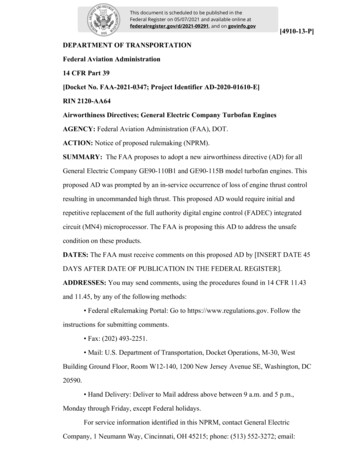
By properly adjusting chiller operating hours, numbers of chillers or applying derating factors, it is relatively simpleto compare many different alternatives,in addition to those described earlier.Keep in mind that this approach is somewhat simplified and in some rare caseswill provide incorrect results. The twomost common instances are where a nightload exceeds the ice-making capacity ofthe calculated chiller and secondly,where the calculated partial chiller sizeexceeds a daytime hourly cooling load,in other words, whenever our originalassumptions of chiller contribution areincorrect. Manufacturer’s selection programs should adjust for these cases.Equipment SelectionFigure 1: Chiller/storage selection (1 ton peak load, 9.5 total ton hours).Equipment must now be selected thatwill provide the necessary capacities. Thermal storage equipment is available in a range of designs, materials and configurations. Performance characteristics can vary significantly.Furthermore, ice storage systems are not steady state devices.In addition to the parameters that affect any heat exchanger,the critical physical dimensions for phase change thermal storage devices vary as storage material is frozen or melted.High rates of discharge and/or lower temperatures are available early in the melting cycle when the ice surface is closestto the heat exchanger, with these capabilities diminishing asthe ice surface recedes from the heat exchanger. This sometimes complex interaction of variable equipment performancewith changing building load makes selection for dischargeperformance critically important.Referring back to our example load profile, the worst casecondition may be during a high load hour such as 15, or itmay be later in the discharge where the loads are lower butthe storage inventory has been reduced. Accordingly, the AirConditioning and Refrigeration Institute’s Guideline T, Specifying the Thermal Performance of Cool Storage Equipment,requires that storage manufacturers provide hour-by-hourcoolant temperatures for the specific equipment selection,load profile and chiller/storage arrangement, thereby guaranteeing adequate storage capacity throughout the designday.2 Merely specifying ton hours of latent storage does notensure that the offered equipment will adequately providethe desired performance.Manufacturers have devised different methods of presenting performance information that is tailored to their particularproduct. Figure 2 presents a segment of the discharge performance for one storage device with a constant coolant inlettemperature of 50 F (10 C).3 The important relationship torecognize is the change in performance as storage inventory isexpended, although the trends are predictable. This particulardevice is capable of providing 20 tons (70 kW) of dischargecapacity with a leaving temperature of 44 F (6.7 C) and having expended 158 ton (556 kW) hours of stored cooling. If thedischarge rate is increased to 30 tons (106 kW), the 44 F (6.7 C)leaving temperature will be exceeded if we attempt to discharge more than 126 ton (443 kW) hours. Likewise, if 40 F(4.4 C) coolant is required from storage at a 20 ton (70 kW)rate, 126 ton (443 kW) hours can be expected. As the rate ofdischarge is decreased, or the required leaving temperature israised, the capacity of the storage equipment is increased. Mostmanufacturers have computerized the selection process so thateach hour of the design day load profile is analyzed to ensureadequate storage capacity.In determining a chiller’s “charging” or ice-making performance, it is usually sufficient to establish the average chillerleaving temperature that the storage equipment requires. Again,charging performance, as reflected in chiller leaving temperatures, will gradually diminish as ice is formed. Because ice hasalmost four times the
chiller selection. As the chiller size is increased above the mini-capacities that eventually approach the demand avoidance of the full storage solution. Alternatively, larger than minimum chillers allow us to select reduced storage capacities to satisfy other design goals such as space restraints. Figure 1 presents two other selection alternatives, although many others are possible. Systems .