Transcription
Traffic Signal TroubleshootingCharles DeVitisUpper Merion TownshipTraffic Signal SupervisorDecember 6th 2018
What does the Signal Techreally need to know.ControllersConflict MonitorsBattery Back Up SystemsFiber OpticsNetworking and SwitchesAdaptive SystemsCentral SystemsPreemptionLoad SwitchesBIU’sPower SuppliesAnd Many More
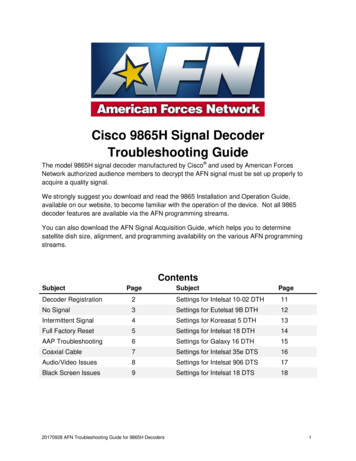
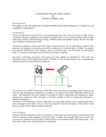
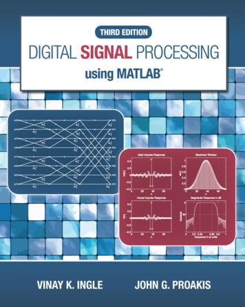
Simplified Controller Cabinet Wiring DiagramO1 RTraffic ControllerChassis Ground21120VACLogic Ground43A OutputA Input R65B OutputB Input Y87C OutputC Input G109 24VDCNo Connection12O1 YO1 G 24VDC11AC CommonThree Circuit LoadswitchCMULoadCircuit#28AC (-)#2#171091211LoadCircuit#1ChassisGroundAC ( )Mercury RelayFlasherFlash Transfer RelayCircuit BreakerFlasher ControlRFYGRFY GNeutral Bus BarGNDAC( )AC ()
Default CU TS 2Channel Mapping
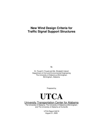
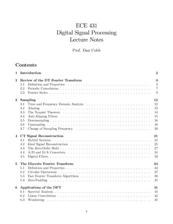
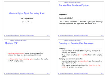
NEMA SIGNAL PHASINGRing 1Ring 215263748Ring 1Ring 215263748Ring 1Ring 215263748Sequential Phases in a Ring are notpermitted to be on at same time. InRing One Phases 1,2,3 and 4 shouldnot be programmed to be on at sametime.Same applies to Ring Two for Phases5,6,7 and 8Phases that are permitted to be on atsame time will be one from Ring Oneand the Phase below it in Ring Two oron the diagonal and not crossing theBarrier.Usually Phases 2 6 are Main Streetand Phases 4 8 are side street.Phases 1 5 are Main streets turnLanes and Phases 3 7 are sidestreets turn lanes.Here is an example of how the turnslanes are defined.Phase 2 turning phase is Phase 5, asyou can see the turn lanes arediagonal from the parent phase.
NEMA SIGNAL PHASINGRing 1Ring 215263748Ring 3Ring 4913101411151216Ring 3Ring 491310141115121616 ChannelsNow we previously learned about a 2ring NEMA Phasing, the same will applyif we add a 3rd and 4th ring to thecabinet. Seen mainly in TS 2 Cabinets. Ifused for Vehicle Phasing. Ped andOverlap we will handle a littledifferentlyRing Three consist of the following:Phases 9 through 12 are for PedestrianMovementsRing Four consist of the following:Phases 13 through 16 are for Overlaps Athrough DAgain we carry over what we learned onpermissive phases from Rings 1 and 2.Can not cross the Barrier and sequentialphases can not be on at same time.
Parent Phase2648R3 Child Phases913111510141216R4 Child PhasesParent Phase2648Ped913111510141216OVLNow I will confuse everyone becausewith Rings 3 and 4 they are slightlydifferent and I will use a new diagram toexplain.Phases 2,4,6 and 8 are Parent Phasesfrom Rings 1 and 2 and this diagramshows their Child Phases.In this Example we show you the newpermissive pairs of rings 3 and 4's ChildPhases and how they are associatedwith the Parent phases of rings 1 and 2.Phase 2 vehicle Phase 9 ped Phase13 overlap APhase 6 vehicle Phase 11 ped Phase15 overlap CPhase 4 vehicle Phase 10 ped Phase14 overlap BPhase 8 vehicle Phase 12 ped Phase16 overlap D
Monitor Cheat Sheet & Trouble Shooting GuideCONFLICTSignal Indication Burned Out Shorted or OpenField Wiring Output side of load Switchshorted Bad transfer Flash relayRED FAILBad Load Switch, EPAC, BIU in TS2CVM/WATCHDOGController found the fault, Police Flash Switch,TS2 Check Frame Faults24V-2 & 24V-1PORT 1 FAILThis is a NON Latching Fault (can be set to latching)The signal will return to normal operation when 24 vdc is restored PowerSupply in TS2Controller in TS1Main Power under 90 Volts ACIf running on Generator bad output powerMin Yellow and RedTime was cut short for Yellow or Red Clearance timesController programmingPreemption programming an overlap for right turn signalTS 2 only faults SDLC Cables, BIU, ControllerDIG/PGM CARDProgram card ajar, Monitor BrokeFIELD CHECKIn combination with Conflict helps determine exact signal indication faultCLEARANCE FAILFAIL DUALINDICATION2 different Signal indications on at the same time same phaseLoad Switch Field WiresTS 1 (conflict monitor) Green and Yellow Light bulb on at same time TS 2ONLY a RED out will trigger this with FIELD CHECK Status enabled Badtransfer Flash relayLOCAL FLASH Police doorEpac incorrect Time of DayKNOWN GENERATOR PROBLEMSIf output power is too high or too low the signal will go in and out of flashIf the frequency of the generators sine wave shifts above or below /- 2 Hertz The MMU andConflict Monitor will keep the signal in flashRED ENABLE or RED FAIL will be the fault on MMU and RE RE will be on ifusing the LCD conflict monitors TS-1Have the police bring out another generator and write down the number on the generator so we can have it removedfrom service
Monitor Cheat Sheet & Trouble Shooting GuideTROUBLE SHOOTING COMPLAINTS from Others/Police CHECKPOLICE DOOR SWITCHES FIRSTMake sure the FLASH SWITCH is in its proper positionSignal in Flash but I also see the green litCHECK Mercury Relay then Flash Transfer relaysAdditional info on a TS 2 cabinet not covered in this manual but covered inour other Trouble shooting seminarPLEASE CHECK THE ALARM PAGES Screens 9-4 & 9-8 & 9-3USE ECOM SOFTWARE OR EPAC SCREEN 9 – 8 check the MMU ALARM REPORTThis will be able to rule out NON LATCHING FAULTS example loss of 24vdcTS 2 ONLYSTART UP FLASH w/PREEMPTBad BIU or preempt inputFirst check screen 1-8 enter frame 138 check bits 22 & 23Second same as above but check frame 139 check bits 24 thru 27 if a “1” is present the BIU or Preempt card is causingthe problemIf replacing the BIU or turning off the Preemption card does not work check that there is no ramp orfirehouse or rail road preemption causing this problem remove wires from backboard or unplug “D” connectorLAST replace ControllerTS 2 DIAG FLASH – NO EXIT A series of repetitive faults that require you to power down and recycle power to thesignal. These faults happen 3 times in a 24 hour period.This is caused by a FRAME FAULT check the equipment that is attached to the SDLC cables FRAME FAULTS 128thru 131 are all related to the MMUFRAME FAULTS 138 thru 141 are all related to the TERMINAL & FACILITIES BIU’s FRAMEFAULTS 148 thru 155 are all related to the Detector racks or Camera ProcessorIn the Seimens Epac Book on page 111 is the Diagnostics section and will explain in detail Also in the bookon page 101 is the LOCAL ALARMS explainedTS 1Active status of the intersectionActive status of the ABC connectors outputThese 2 screens will show you what color R, Y, G is on for its corresponding phaseWhen STOP TIME is on because of a fault you can now narrow down what signal colors are giving you a conflictor dual indication
Monitor Cheat Sheet & Trouble Shooting GuideON ALL TIMING COMPLAINTS check in this orderTIME OF DAY remember MILITARY TIME is used DETECTORS &CAMERAS for faults or miss aligned cameraCheck Locking Non LockingPut the phase into MAX RECALL if NO CALL is being generated VERY RARECheck next paragraph for help on changing vehicle recallsPHASE DATA make sure it corresponds to the Signal Permit Density timesPedestrian times Vehicle and Ped RecallsPhases 2 and 6 are usually are set for MIN RECALLAll other phases are set at No recall unless loop is broken then Max Recall BrokenPedestrian Button MIN RECALL NEVER MAX RECALLMax Recall messes up volume densityProtected Turns PhasesHave a dedicated 3 Section head for this movement We wantLOCKING memoryProtected Permissive Turn PhasesHave a 5 section head dedicated for this movement example Phases 1 6We want NON-LOCKING memory Example the TURNING movement usually phases 1 or 5 and 3 7Side Streets Phases 4 & 8Non Locking Memory unless Signal plan calls for LockingNo Recalls should be under these phases unless Signal Plan calls for a recall
A logical thought process7 Step Isolation Procedure1. Observe intersection operation2. Identify the problem or problems3. Determine the general areas that could create the observed symptoms4. Make tests or take steps to isolate the actual area causing the problem5. Make tests to determine the device that is causing the problem6. Replace the defective device or otherwise correct the problem7. After corrective measures are completed, thoroughly observe intersectionoperation to ensure that all problems have been corrected.
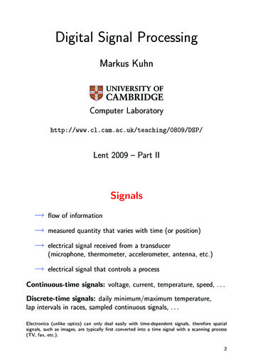
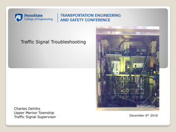
Check Load Switchfor the PhaseOKFlashingIntersectionMove Load Switch to aDifferent LocationCheck ControllerOutputs on that PhaseDefine the Problemand ConditionsControllerNotSureYesNoDuelOutputsReplace Load SwitchReplace Controller YesCheck for Bad RelayContactConflict MonitorOKWrite DownInformationCheck for Debris onBack Side of PanelBadContactsReplace RelayYesRemoveDual IndicationOKCheck Cannon Plugsfor DebrisTwo or More IndicationsDetected on the SameChannelCleanIsolate Phase at theField TerminalsTemporarily Loadthe Field TerminalsYesReset Monitor withNoCAUTIONFieldCheck Field WiringLook for a CommonPoint Where TwoIndications MeetCabinetCheck Field TerminalsFor Contact BetweenField OutputsYesCheck for ProperSignal OperationYes13-17
Check Field WiringThings to check:Shorted wires, openneutrals, burned outsignal lampsDefine the Problemand ConditionsMove load switch to adifferent locationFlashingIntersectionControllerLook for loose wires in thecabinet making contact onthe field terminalsCheck load switches for aconflicting outputsNo tSurNoeCheck forconflictingcontroller outputsYesConflict MonitorReplace load switchYesNoYesWrite DownInformationReplace ControllerCheck for bad relaycontactsConflictYesVoltage DetectedConcurrently ( 450m sec.)on any conflicting channelsReplace RelayNoRemember thewiring diagramIs the monitor cardprogrammed?YesRemoveIsolate the conflictingchannels / phases atthe field terminalsNoCleanProgram the monitorcardTemporarily loadthe field terminalsReset monitor withCAUTIONYesNoYesFieldYesCabinetCheck for debris onthe back side of thepanelNoCheck cannon plugsfor debrisCheck for ProperSignal Operation13-20
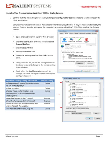
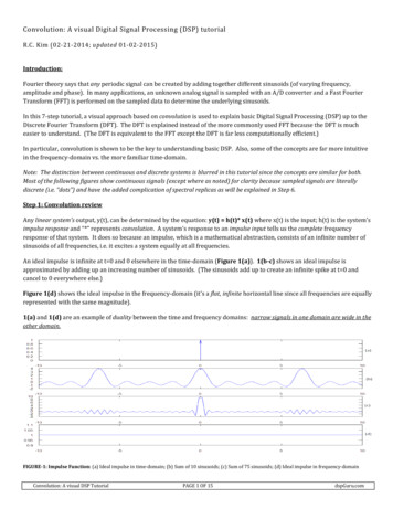
ECom Signal SoftwareFor use with Eberle Design brand of Conflict MonitorsDisplay Real- TimeStatusWhy guess when you can know? Real time status shows all signalstates, field terminal voltages,and cabinet control voltages.Current fault type and faultstatus is displayed with timeand date stamp.Channels involved in the fault aredirectly indicated.View a display that graphically displays signal On/Off states as well as the RMS voltage at each field terminal and at the AC Line input. Itis like having a 48 channel digital voltmeter connected to the cabinet 24 hours a day, 365 days a year. When a fault is detected the realtime status is latched as a snap-shot of the cabinet status at the time the fault was detected. The fault type is displayed with the time anddate of the event. Channels involved with the fault are also directly identified.
MMU acts like 48 individualVolt meters on every signal output
Phases 2 6 Normal Operation
Where do SignalTechnicians receivetraining ?New Jersey Sectionof the IMSAPassed downtraining within theDepartmentLocal SignalSuppliers
Troubleshooting Tips Always remember, in a TS 2 facility, the CU and the MMU shareresponsibility in looking for problems, and either may initiate aflash condition if one is detected.The following three steps will usually provide enough informationto diagnose most problems in a previously working facility Look at the Alarms log Look at the MMU fault log Look at the Ring Status for Rings 1 & 2 If you are physically at the facility, the indicator LEDS on the MMUand BIUs frequently provide convenient information. The CU exerts control over the MMU using the CVM line (ControllerFault Monitor Output). Therefore, the MMU will usually not latchinto a fault state for a serious problems first detected by the CU.
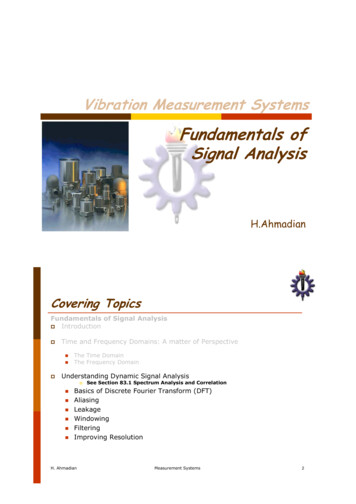
Troubleshooting TipsExample CU ScreensSTOPTIMERing status Ring 1 and Ring 2RING 1YELRING 24 YELGAP OUTPHS.12345678 901234564 O/NGAP OUT.O.O. .VEHCCCCCCCC .PEDRRRRRRRR .H/O. OOOOOOOOLOCK OUT -MAX OUTMAX OUTSTOPTIME – 1/2If the facility is in relay flash, but the load switchLEDs are lit and not flashing, then the MMU hasmost likely detected a problem before the CUand is holding the CU in stop time. The MMUmay, or may not, be latched at this point,depending on what the problem was. The CUlogs should have information about the natureof the problem.
Troubleshooting TipsExample CU ScreensTS 2 DIAG FLSH – NO XITRing status Ring 1 and Ring 2EPAC RING TIMERSSEQ: 00RING 1PHS.12345678 90123456RING 2F-PRIOR MENUMGRN11 MGRN11 O/N.O.O .WALK3 WALK3 VEHCCCCCCC. .PEDRRR.RRR. .H/O. OOOOOOOOPASS4 PASSMAX131 MAX12 TS2 DIAG FLSH - NO XIT31The controller has detected either a nonrecoverable TS 2 error, or has had threeoccurrences of a fault for an individual T&F BIU.This will require a CU reset either by powercycling, or using the 3, 5, 9 screen. The MMUmay, or may not, be latched, depending on thespecific problem.
Troubleshooting TipsExample CU ScreensBIU T&F cable disconnectedEPAC SYSTEM - LOCAL ALARMS REPORTMM/DDHH:MM4/ 115: 3-------STATUS------FRAME 138 FAULTA-PRV B-NXT WINDOWC-CLEAR F-PRIOR MENUFrame 138 is associated with T&F BIU #1, sochecking the BIU would be the first reasonabletroubleshooting step.
Troubleshooting TipsExample CU ScreensCU SDLC cable disconnectedCable disconnected from CUEPAC SYSTEM - LOCAL ALARMS REPORTMM/DDHH:MM-------STATUS-------4/ 115:12FRAME 139 FAULT4/ 115:12FRAME 128 FAULT4/ 115:12DIAG: RESP FRAME FAIL4/ 115:12FRAME 129 FAULT4/ 115:12DIAG: RESP FRAME FAIL4/ 115:12FRAME 138 FAULT4/ 115:12FRAME 148 FAULT4/ 115:12FRAME 149 FAULT4/ 115:12FRAME 150 FAULT4/ 115:12FRAME 151 FAULT4/ 115:12FRAME 131 FAULT4/ 115:12DIAG: RESP FRAME FAIL4/ 115:12FRAME 152 FAULT4/ 115:12FRAME 153 FAULTA-PRV B-NXT WINDOWC-CLEAR F-PRIOR MENUA failure of this magnitude usuallyindicates an electrical problem with theSDLC bus, or a problem with the CU itself.
The New Tool for the Signal Technician
Managed Network Switch
Traffic Adaptive Signals require knowledge of how tooperate a computer and some advanced computer skills
Future for the Signal Tech
Complex signal repair
The End
CHECK Mercury Relay then Flash Transfer relays TS 2 ONLY PLEASE CHECK THE ALARM PAGES Screens 9-4 & 9-8 & 9-3 USE ECOM SOFTWARE OR EPAC SCREEN 9 –8 check the MMU ALARM REPORT This will be able to rule out NON LATCHING FAULTS example loss of 24vdc START UP FLASH w/PREEMPT Bad BIU or preempt input First check screen 1-8 enter frame 138 check .File Size: 2MB