Transcription
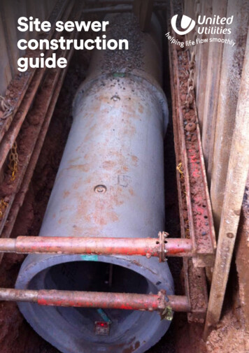
Site sewerconstructionguideUnited Utilities Site Sewer Construction Guide 1
IntroductionContents3Introduction444555Safety in sewers and excavationsTrenches and excavationsControl of site and trench groundwaterAgreed drawingsConstruction materialsStorage of materials6666788991314Manhole chambersTypical manhole chambers up to 3m deepSizing of manhole chamberManhole base and channel constructionChannelsLateral connection manhole channelsManhole benchingStub and rocker pipesSetting out position of 1st ring and coverslabManhole rings, step ironsLaddersCover slabs and access openingsPositioning of cover slabsAdjusting brickwork, raising pieces andmanhole cover and framesEnglish Bond adjusting brickworkManhole cover and frames1515151515151616Pipes and beddingSewer pipes and bedding specificationHandling and storage of pipesProtection of sewersPipe BeddingRecycled pipe bedding materialsLaying and jointing of pipesBackfilling101011121317171717Testing of sewersAir testingWater testingCCTV surveys18 Connections18 Connections to existing public sewers18 Connections to existing public sewermanholes19 New manholes on existing public sewers20 Pre-formed junction connections20 Core-drilled saddle connections20 Back drop connections21 Access21 Bespoke or manhole chambers forstorage systems22 Alternative access arrangements forlarger diameter surface water sewermanholesThis document has been produced as anon-site guide for contractors and operativesconstructing sewers, with advice notesprovided to avoid some of the common onsite errors.23 Typical surface water flow controlmanholeAgreed agreement drawings andmanufacturer’s recommendations should beadhered to. Should this not be practicable,design changes or amendments mustbe agreed with United Utilities beforeconstruction.24242424It is a contractor’s responsibility to ensurethat all operatives are competent andexperienced to complete works to therequired standards.Fixings and railsMetal fixings and chainsSafety chainsHand rail and balustrades25 Other information25 Typical 1:20 manhole details26 Other contact information and adviceKeep this booklet with you on siteas a quick reference guide2 United Utilities Site Sewer Construction GuideSewers are expensive to constructand if not built correctly, remedialworks can be disruptive, timeconsuming, costly and in somecircumstances, have adverse effectson a company’s reputation. Inmany instances, a lot of mistakescan be avoided by considering thespecification and requirementsbefore and during construction.SAFETY IN SEWERSThe Health and Safety of workers on thePublic Sewer Network is our number onepriority. All work on public sewerageapparatus must be agreed in writing byUnited Utilities (see page 26 for furtherdetails). As a minimum requirement,workers carrying out sewer constructionon the public sewer must hold a currentCity and Guilds or SQA standard orCABWI Level 2 Award Certificatefor Working in Medium or High RiskConfined Spaces in the Water Industry.In addition, those carrying out the workmust be suitably experienced.All excavation works should be carriedout in a safe manner taking into account: underground services and structuresconfined space workingground conditions and collapsespreventing fallssafe access and egressREMEMBER: Access to the public sewernetwork must be agreed in writing. Youmust ‘Log On’ before starting workand ‘Log Off’ the sewer network bytelephoning 0782 653 94 59 and quotingthe unique Access Certificate or SewerConnection reference number.Version 1.0 October 2015EXOnly Intrinsically SafeCCTV equipment canbe used in public sewersUnited Utilities Site Sewer Construction Guide 3
Safety in sewers and excavationsSafety in sewers and excavationsTrenches and excavationsAgreed drawingsTrenches must be adequately supported, freefrom boulders and tree roots must be takenout. Muddy ground, water and soft areas inthe trench base must be removed. Materials,spoil and equipment must be stored safelyand plant should be operated within a safeworking distance. The trench must beadequately protected from slips, trips, falls,site traffic and have a safe means of accessand egress.For sewer adoption and diversion works,construction must comply with the drawingsagreed by United Utilities. Similarly for publicsewer connections, works must comply withthe details which have been agreed by theLocal Authority, the relevant Building ControlAuthority and the approval given by UnitedUtilities for the works to proceed.It is recommended that a site copy of theagreed drawings are available to thosecarrying out construction to avoid anymistakes or deviation from specification.Trenches should be adequately dewateredto provide a firm base but not dug widerthan necessary as excessive loading may beplaced on the pipe. Should ground conditionsbe unsuitable for pipe laying and manholeconstruction, please consult with yourengineer to design a solution.Any deviation from the agreed drawingsmust be agreed with United Utilities beforeconstruction.Control of site and trenchgroundwaterThe discharge of site ground water andexcavation dewatering to the public seweris only permitted by approval from UnitedUtilities in writing. In addition, care mustbe taken to prevent site debris, sludge orsilt from entering the sewer network whichcould ultimately cause flow restrictions,blockages, flooding, pollution and also affectthe receiving wastewater treatment works.Costs associated with such incidents maybe recovered from those responsible. Inaddition, should an inappropriate dischargeof site groundwater or construction materialcause a pollution incident, this may lead toprosecution.Do not let site water enter thesewer network.Construction materialsStorage of materialsAll materials including pipes must complywith the United Utilities agreed drawingsto Water Industry Standards (WIS) and beKitemarked or have a similar EU certificationmark. Should it be necessary to change to analternative product or material, this must beagreed in advance with United Utilities, beforeconstruction commences.All materials should be handled with careand stored safely in accordance withmanufacture’s recommendations.Please note when ordering, suppliers shouldbe made aware that the products selectedmust comply with United Utilities StandardDetails and the current edition of Sewers forAdoption specification.Discharge to public sewer only permittedby approval from United Utilities in writing4 United Utilities Site Sewer Construction GuideUnited Utilities Site Sewer Construction Guide 5
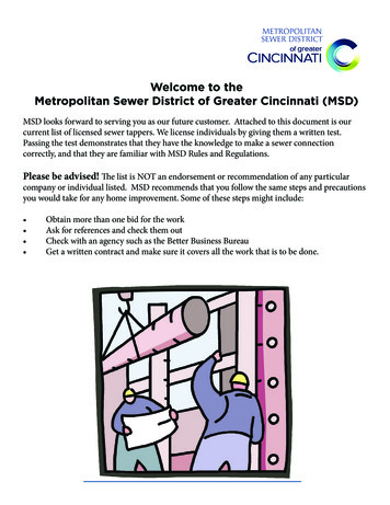
Manhole chambersManhole chambersTypical manhole chambersup to 3m deepChannelsSTUB PIPEManholes should be constructed where thereis a change of direction and/or a change ofgradient, or where access is required formaintenance purposes. Such changes indirection or gradient must be made withinthe channel and not outside of the manholeor concealed by benching.Manhole bases should be sized toaccommodate the main channel, lateralconnection channels and provide a minimum600 x 600mm square landing area beneaththe step rungs or ladder for main channels upto 375mm. However, should there be severalchannels, the size of the chamber may needincreased. Please note, road cambers shouldbe considered when positioning manholeswith double covers across the centre of acarriageway.STUB PIPEManhole base and channelconstructionRemember 600 x 600mm square landingarea must be provided below the loweststep or ladder rung for sewers up to375mm diameter.Chamberdiameter“X” 30001700The manhole base should be a minimum of225mm deep to the barrel of the channel.To prevent the ingress of ground waterand associated calcified deposits bleedingthrough the benching, the concrete shouldnot be a dry mix and sufficiently compactedor pokered to remove voids and entrained air.Channels must be steep sided to at least thecrown of the pipe.UU Type 4 manhole 1.5m deep6 United Utilities Site Sewer Construction GuideThe pipe joint adjacent to the channelshould be a minimum of 100mm fromthe internal face of the manhole.Lateral connections into the manholemust also enter the chamber aschannels, again at 100mm from theinternal face of the chamber andconnect to the main channel at soffit tosoffit level, swept with the direction ofmain flow.Manholes should also be positioned 0.5maway from curb lines, preferably with themanhole cover positioned away from thewheel line of traffic.Sizing of manhole chamberMinimum lengthof channelSteep sided channel topipe crown or above.Channel typesBenching should be selfcleansing and formedwith high strengthgranolithic screed at agradient of between 1:10– 1:30.Channel inverts must be constructed using channelfittings for pipe diameters up to 300mm. Clay andsuitably fixed plastic channels are acceptable.Granolithic channels formed for smaller diameterchannels often are either not sufficiently finishedor the profile of the channel is not maintained,causing the accumulation of solids and associatedodour complaints and as such are not acceptable.Granolithic channels above 300mm diameter mustbe finished with a steel float.Min 225mm concretebase, with 75mmblinding.Preformed plastic bases constructed within manholePreformed plastic inspection chamberrings are also not permitted. Preformed concretebases must not be installed within manholeand plastic coated concrete bases are permitted.rings or brickwork chambers.United Utilities Site Sewer Construction Guide 7
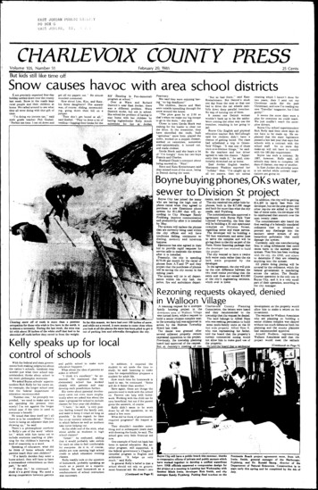
Manhole chambersManhole chambersLateral connectionmanhole channelsStub and rocker pipesRocker pipes mustalso be installed forpre-formed basesThe manhole stub pipe must terminate within150mm from the external face of the manhole.The length of the rocker pipe used mustcorrespond to the sewer diameter. For sewersup to 600mm diameter, the rocker lengthmust be 500– 750mm long.Lateral connections within manholes mustmeet the main channel at ‘soffit to soffit’ levelwith the channel commencing 100mm fromthe chamber wall.All lateral channels must meet the mainchannel, swept in the direction of the mainflow.Please note, no rocker pipes are requiredon concrete pipes in excess of 1050mmdiameter.Setting out position of 1string and cover slabManhole benchingBenching should be self-cleansing and formedwith high strength concrete at a gradient ofbetween 1:10 – 1:30.Gradient betweenbetween 1:10 – 1:30.The underside of the manhole ring must besituated between 50 – 300mm above thecrown of the pipe.Min 50mmMax 300mmThe distance from finished ground level tothe top step rung beneath the cover slabmust not exceed 675mm. A minimumdistance of 150mm between the undersideof the cover slab to the top step iron mustalso be provided.To maintain a smooth flow within the mainchannel, the benching must be formedvertically from the edge of the channel to atleast the crown of the pipe.It is recommended that your site engineersets out the cover slab, concrete baseand manhole ring levels to ensure thatthe above distances are provided.The edge of the step rungs must be plumb and inalignment with the edge of the cover slab opening.Vertical benching to at leastthe crown of the pipeThe top rung of ladders must also be no greater than675mm from ground level, with the rungs positioneda minimum of 211mm from the chamber wall to thecentre of the rung.8 United Utilities Site Sewer Construction GuideUnited Utilities Site Sewer Construction Guide 9
Manhole chambersManhole chambersManhole rings and step ironsThe distance from ground levelto the 1st step or ladder rungmust be no more than 675mm.Remember the top step mustbe a minimum of 150mm fromthe underside of the coverslab. A site engineer should setout the cover slab levels priorto construction so that thisspecification is achieved.The step rungs must be plumb,in vertical alignment andequally spaced, leading to alanding area of a minimum areaof 600 x 600mm square fromthe edge of the main channel tothe chamber wall.750mmGenerally, where manhole chambers arebetween 1.5 – 3.0m deep from finishedground level to benching landing area, a600 x 600mm clear unobstructed opening isnormally suitable.Positioning of cover slabWhere chambers are less than 1.5m deepfrom finished ground level to benchinglanding area, consideration should be givento accessing and carrying out maintenanceactivities within the chamber.600mmIn areas of traffic loading, highground water table levels orcontaminated ground, 150mmGEN 3 concrete surrounds tomanhole chambers must beprovided. Alternatively, widewall rings can be considered.For 600 x 600mm square openings on1050mm diameter chamber rings and above,United Utilities Standard Detail Specificationis that a 600 x 750 mm cover slab is fitted,reduced to a 600 x 600mm square openingby the use of an eccentric raising piece to suitthe manhole cover and frame used.600mmManhole rings must beseated on a mortar bed andadequately pointed to preventthe ingress of ground water.Alternatively, proprietarybitumen or mastic beddingmaterials can be used.Manhole ring lifting eyes mustbe pointed flush with thechamber walls.Cover slabs and access openingsFor 1050mm and 1200mm diameter rings lessthan 1.5m deep to benching, 750 x 750mmcovers shall be fitted.675mm(max)For 1500mm diameter rings less than 1.5mdeep to benching, 1200 x 675mm covers shallbe fitted.Please note, cover slabs must not be cutto increase opening dimensions as this willsignificantly weaken the cover slab.LaddersStainlesssteel ladderRing chamber walls600mmWith opening reductionTo maintain a600 x 600mm squareclear opening, thestep rungs or laddersmust be plumb andin alignment with thecover slab opening.Where the distance from ground level to the benchinglanding area is in excess of 3m, step irons are not permittedand a ladder must be installed. Stainless steel or in certaincircumstances GRP ladders are acceptable, but pleaseconsult with United Utilities who will confirm the relevantspecification.10 United Utilities Site Sewer Construction GuideUnited Utilities Site Sewer Construction Guide 11
Manhole chambersManhole chambersPositioning of cover slabsAdjusting brickwork,raising pieces and manholecover and framesCover slabs must be positioned in squarealignment with step irons or ladders andprovide a minimum 600 x 600mm squareunobstructed opening. The internal face ofthe cover slab must be plumb with the outeredge of the step irons.Remember, thedistance fromground level tothe 1st step shouldbe no more than675mm.1-3 courses of solid Class B engineering bricksshould be used, free from thin masonry splitsconstructed using 3:1 cement sand mortarin English Bond. Please note, normal housebuilding mortar is unsuitable for constructingadjusting brickwork. Furthermore, masonrysplits should only be used to achieve roadcambers and gradients.Remember, thetop step must bea minimum of150mm from theunderside of thecover slab.Alternatively, pre-cast raising pieces can beused, bedded on 3:1 sand / cement mortaror stronger. Proprietary shimming piecesshould be used to achieve road cambers andgradients etc.Please note when calculating the number ofmasonry courses, the mortar bed beneath themanhole frame must not exceed 12mm.Step rungsmust not beconstructedin adjustingbrickworkopenings.Both adjusting brickwork and raising piecesmust be of sound construction, plumb, inalignment with the cover slab, free from holes,mortar snots with the mortar joints suitablypointed or flush with the brickwork. Pleasenote, the rendering of adjusting brickwork orconcrete seating rings is not permitted.English bond adjustingbrickworkEnglish bond must be constructed as perthe diagrams below taking particular care toensure that the bond is maintained throughoutthe courses with no vertical straight joints,using 1/2 brick Queen Closures at the corners.Defective or damaged cover slabs must bereplaced.12 United Utilities Site Sewer Construction GuideUnited Utilities Site Sewer Construction Guide 13
Pipes and beddingManhole chambersManhole cover and framesSewers for Adoption specifies that allmanhole frames located in adopted highwaysmust be a minimum of 150mm deep and only100mm frames are permitted in residentialcul-de-sacs. Covers must be Kitemarkedand comply with BS EN124 with ClassD400 covers used in all areas used by roadvehicles. It is however recommended that allcover and frames subject to traffic loadinghave 150mm deep cover and frames fitted.Should you have any queries with regards tothe suitability of manhole covers and frames,please clarify the requirements with UnitedUtilities.Before final surfacing, it is recommendedthat all frames are checked for alignmentand sound bedding. Resetting frames andassociated reinstatement can be costly, timeconsuming and spoil the appearance of anewly surfaced area.Inappropriate bedding of manhole framesoften leads to movement of both themanhole cover within the frame and thedisintegration of the surrounding ground,especially in trafficked areas.Generally covers must be bolted togetherwith manhole key holes free from debris andready for inspection.Block paved or masonry inset covers mustnot be installed on United Utilities publicsewerage apparatus.Manhole covers must be correctly selected inaccordance with the given location and mustbe correctly seated in alignment with theadjusting brick work or raising pieces below.14 United Utilities Site Sewer Construction GuideSewer pipesand beddingspecificationPipes used on main adoptablesewer lengths must complywith Sewers for Adoption specification.Should there be any queries as to thesuitability of materials, these should beclarified before construction. Vitrified claypipes should comply with requirements BSEN 295 for foul pipes and BS 65 for surfacewater pipes.Thermoplastic structural walled pipes mustcomply with Water Industry Standard 4-35-01and achieve Class 8k/Nm2 nominal short termring stiffness. Please note, not all structuralwalled pipes meet this specification andpipes which do not meet these requirementsare unacceptable. Pipes must be Kitemarkedor have a similar E.U. certification mark.Protection of sewersSewers located within highway or areas oftraffic should have 1.2m of cover. In otherareas, 0.9m of cover is required. Where thisis not possible, a full protective concrete bedand surround must be provided, inclusive offlexible joints.Pipe beddingPipes must be evenly bedded alongthe length of the pipe. Under normalcircumstances, United Utilities’ specificationfor the bedding of pipes is Class S, full bedand surround for rigid, semi rigid and flexiblepipe materials. Please consult with the pipemanufacturer’s recommendations and agreeddrawings.Handling and storage ofpipesPipes are expensive and should be handledwith care and stored safely in flat areas,away from excavations, stacked no greaterthan manufactures recommendations. Inparticular, PVC pipes should be stored onsurfaces that prevent distortion of both thepipe circumference and linear profile.Recycled pipe beddingmaterialsRecycled materials must comply withBS 8500-2.United Utilities Site Sewer Construction Guide 15
Testing of sewersPipesLaying and jointing of pipesBackfillingPipes should be laid in 3m maximum lengthswith the joints ‘pushed home’ into sockets.Furthermore, care must be taken to ensurethe pipe jointing seals are free from grit, siltetc. which will likely cause the pipe length tofail later air testing. It is recommended thatsewers are air tested at regular intervals aspipes are laid.Pipes should be backfilled and compactedin 150mm layers to 300mm above thepipe crown. Care should be taken duringcompaction so that the sewer remains ingood line and level, in particular adjacent tomanhole chambers to prevent rocker pipesbeing pushed down from stub pipes.Pipes should be cleanly cut, be free fromdefects and laid without back fall and dips.It is recommended that sewers are laid usingpipe lasers to achieve a single consistentgradient. Where there is little fall such asgradients up to 1:150 extra care should betaken to
Public Sewer Network is our number one priority. All work on public sewerage apparatus must be agreed in writing by United Utilities (see page 26 for further details). As a minimum requirement, workers carrying out sewer construction on the public sewer must hold a current City and