Transcription
A Building Inspector’s Guideto Steel Frame ConstructionSteel Framing Inspection Guides t e e l f r a m i n g . o r g
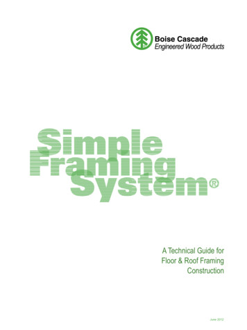
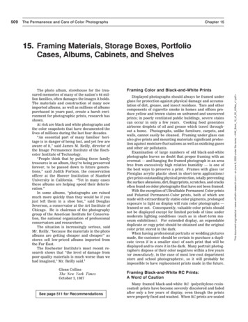
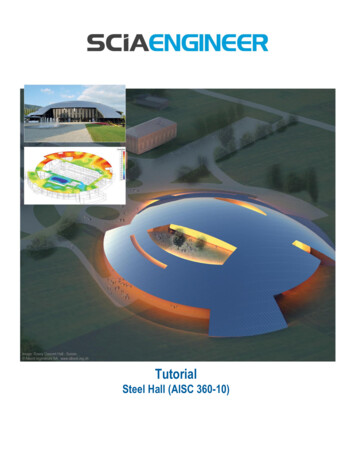
STEEL FRAMING INSPECTION GUIDESTEELFRAMINGINSPECTIONA N E A S Y- T O - U S E G U I D E F O R S T E E LIntroductionSTEEL FRAMINGCold-Formed Steel (CFS) Is:Cold-Formed Steel Parts Strong – steel has the highest strength-toweight ratio of all structural building materials Inert – studs and joists won’t swell, shrink oroff gas with climatic changes Ductile – CFS frames perform well in high windand seismic zones Fire Resistant – steel frames are ideal forareas of high housing density and frequentwildfires Ferrous metal – steel is dimensionally stableand will not provide food for termites, insectsand mold Recyclable – domestic CFS products have aminimum recycled content of 28%Cold-formed steel (CFS) studs and joists are hollow Cshaped sheet steel members that are used to frame walls,floors and roofs in residential and commercial structures.In residential designs that follow the prescriptive methodoutlined in building codes, structural members will bearranged in-line and platform framed.CFS has been durability-tested in the commercial sectorwhere steel frames have been designed and connectedto withstand climatic rigors like tornado and hurricanewinds, earthquakes, wildfires, and insect infestation. Today,designers and builders are increasingly specifying CFS as thestructural frame for homes – from suburban singles to multistory, multi-family and multi-function buildings. This guide willintroduce the building inspector to steel frames and provide auseful aid for residential CFS framing.Refer to the approved design or recognized design standardfor specifics (which govern over this Guide). Cold-formedsteel refers to five common shapes that are rolled from sheetsteel to form components that can be assembled into thestructural framework of a building. The shapes are known bythe acronym S-T-U-F-L, for Stud, Track, U-channel, Furring,and L-header.Cold-Formed Steel ShapesStud or Joist2steelframing.orgTrackU-channelFurring ChannelL-header
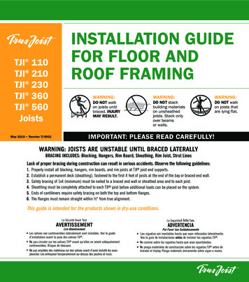
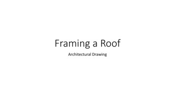
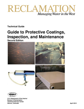
NF RGUIDEAME CONSTRUCTIONSteel Member using the UniversalDesignation System800WebDepthS162- 54Stud 1-5/8”Minimum ThicknessShape Flangein mils(1.625”)(0.054” 54 mils)LipConformance to StandardsBuilding codes and standards require that steel framingmembers be labeled with the manufacturer’s identification,minimum uncoated steel thickness, yield strength and(corrosion protection) coating designation.Some labels on cold-formed steel may follow theuniversal designation system shown above which includesmanufacturer, web size, steel shape, flange size, thickness,and yield strength. Stud (and joist or rafter) shapes have aweb, two flanges with lips. Track will have a web and 2 flangesbut no lips, so that it fits over the ends of studs and joists.Cold-formed Steel IdentificationShape and Dimensions6.00” x 1.625” StudYield StrengthSteel Thickness(in mils)Web and flange sizes are expressed in 1/100ths of an inchand thickness is expressed in 1/1000ths of inch, or “mils.”Using the CFS universal designation system, the stud shownis a 6.00” x 1.62” stud shape of 50 KSI (kips per square inch)steel.Corrosion ProtectionSteel studs are galvanized to protect the steel againstdeterioration from oxidation. The level of protection that isprovided is measured by the gross weight of the metalliccoating applied to the surface area of the steel on allsides. The higher the number is, the thicker the coating.Zinc metal is often used in the galvanizing process of CFSbecause it provides an impervious barrier between the steeland corrosive elements in the atmosphere - moisture andcorrosive chlorides and sulfides. The zinc will corrode beforethe steel until it is entirely consumed. A minimum protectivecoating of G60 (conforming to ASTM A653, ASTM A792, orASTM A875) is required for structural members, while nonstructural, interior framing members may have a minimumcoating of G40.ConnectionsThe IRC 2006 covers structural connections using No.8 and No. 10 screws with a minimum of three threads(approximately 3/8” of the screw shank) extending past thefinal member (backside) of the connection. Generally, No. 10sare required for roof member-to-member connections andNo. 8 fasteners are appropriate in other locations. Gypsumboard can be attached to steel of 33 mils and less with No. 6screws. Thicker CFS will require No. 8 screws. There are pinnails approved for gypsum application, as well.Codes also recognize bolted and welded connections.Fastening methods like clinching, riveting, and pneumatic pinnailing are also permitted. The alternative materials sectionof the codes, provides for case-by-case approval by thebuilding official.steelframing.org3
STEEL FRAMING INSPECTION GUIDESTEELFRAMINGINSPECTIONA N E A S Y- T O - U S E G U I D E F O R S T E E LBuilding CodesCodes developed by the International Code Council havebeen widely adopted as building standards in the UnitedStates and, as such, will serve as primary reference in thisField Guide. Both the International Building Code (IBC) andInternational Residential Code (IRC) include provisions forconstructing with cold-formed steel in commercial andresidential buildings. Citations to the building code that arecontained in this guide will refer to the prescriptive methodfor steel construction in the IRC and referenced standards.The References section at the conclusion of this guideprovides more comprehensive coverage of both IRC and IBCdesign references for CFS.The American Iron and Steel Institute’s (AISI) (2004) Standardfor Cold-formed Steel Framing-Prescriptive Method for Oneand Two-family Dwellings 2001 Edition with Supplement 2(AISI COFS/PM) is an industry standard that is referenced inand considered to be a part of the IRC 2006.ENGINEERED DESIGNSSteel can be used differently in engineered designs thanit can be used by following the prescriptive methods in theIRC. Engineered designs analyze the stud, joist, header, androof components as columns, beams, and rafters for themost efficient use of the material. Thus, each component isindividually engineered for a specific design, so the spacingbetween structural members and thickness of the steel canvary widely in engineered designs. Engineered CFS designsare acceptable alternatives to a prescriptive design. Nongeneric steel is frequently used in residential constructionwhere proprietary products, like floor joists with large utilitypunchouts, meet the need for cost effectiveness andmechanical system integration.Cold-formed steel studs of 33 or 43 mil thicknesses arefrequently specified for structural applications in residentialdesigns. Thicker steel is heavier to handle and cut, moredifficult to seat fasteners into, and more costly. Track is the4steelframing.orgnon-structural end cap to C-shapes – both studs and joists– and is specified to the same thickness as structural studsand joists/rafters.MECHANICAL, ELECTRICAL AND PLUMBINGINTEGRATION IN STEEL FRAMESPunchouts in the web of studs, joists, and rafters providea ready pathway for mechanical, electrical and plumbing(MEP) runs. Grommets, bushings and isolators can beused to protect wiring or piping from the sharp edges of thepunched opening in CFS or to separate reactive metal, likecopper, from the steel. These plastic accessories that cap thepunchouts can also provide intermittent support to the MEPsystems, and are typically snapped in place prior to wire orpipe installation so they remain permanently affixed to theCFS. Wire ties secured through punchouts may be used tohold wire that parallels a CFS member.Field punchouts are permitted in the webs of CFS withinstated tolerances. Drills with hole saw or unibit attachments,punches, and plasma cutters are some of the tools that canbe used to make holes in steel. Field installed holes shouldbe located along the centerline of the member, cannot belarger than 4 ½” in length and 1 ½” to one half the member’sdepth (dependent on member width), and should be spaceda minimum of 24” on center and a minimum of 10” frommember end or end of bearing location. Hole patches of thesame thickness of steel as the member secured with No. 8screws at one-inch spacing are allowed in webs only.Pipe InsolatorGrommet or bushing
NF RGUIDEAME CONSTRUCTIONsteelframing.org5
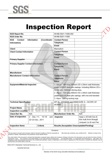
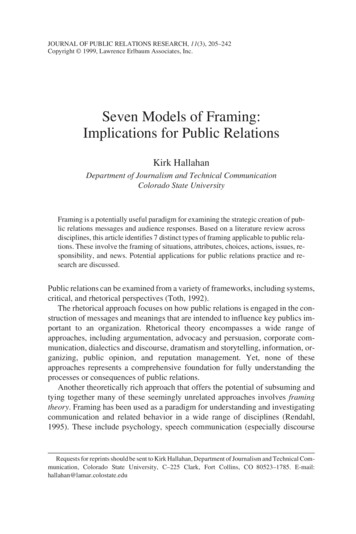
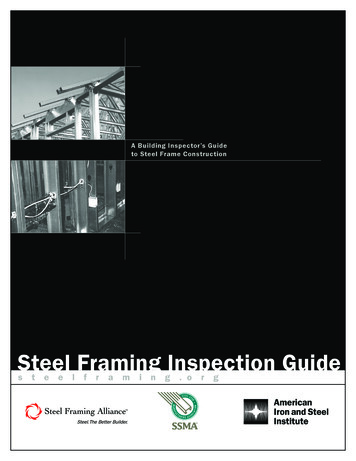
CONSTRUCTIONDETAILSFOR STEEL FRAMING INSPECTORSRIDGEMEMBERCONNECTION Nest track and joist to form a ridge memberTRACKSPLICE Stud section of same thicknessBOXBEAMJOISTHEADERBLOCKING- STRAP In lieu of solid blocking With gypsum board bracingCORNER Two joists and track Cripple studs Structural sheathing one faceCANTILEVEREDFRAMINGFLOOR Top track overlap Web stiffener Blocking Clip angle with bolt6steelframing.org
STRAPATROOA FND EAB VL EOCKINGINLINESINGLE Solid blocking between rafters Strap bracing at top chord flangeFRAMINGLHEADER Maximum ¾” toleranceSOLIDBRACINGBLOCKINGBottom Chord Bracing ½” gypsum board, or Flat strap Cut track Between bottom chord strap bracing Int. bearing at continuous joist(every other joist) Joist or track, 33 mils RFOUNDATIONWA CL OL NNT EO CTION Track Bolt and Washer Web Stiffener Rim Track Clip Angle and Boltsteelframing.org7
STEEL FRAMING INSPECTION GUIDE8steelframing.orgSTEELFRAMINGINSPECTIONA N E A S Y- T O - U S E G U I D E F O R S T E E L
NF RGUIDEAME CONSTRUCTIONCODE AT A GLANCE – FLOORSSUBJECTREFERENCEIRCAISI COFS/PMCONVENTIONBearing stiffenerR505.3.4 Bearingstiffeners118B2-113Bearing stiffeners installed at all bearing locations for steel floor joists. Stiffeners minimum33mil C-section or 43 mil track section.BlockingR505.3.1112D5-1D5-22526Blocking can be solid joists or x-brace strapping at mid-span of joist with maximumspacing of 12’.Bracing top flange, floorjoistsR505.3.3 Joistbracing11318Top flanges of steel joists laterally braced with floor sheathing fastened to the joists.11318Laterally brace floor joist bottom flanges where spans exceed 12’ with gypsum board orcontinuous steel strapping, blocking or bridging.22-24Cantilevers cannot exceed 24” with a min. of 6’ back span. Only one story of cantileversis allowed.Bracing bottom flange,floor joistCantilevers, floor joistsR505.3.7 Floorcantilevers121D2-4 D2-7Cutting/notching, floorjoistsR505.3.5 Cuttingand notching113Flanges and lips of load-bearing steel floor framing members shall not be cut or notched.Dimensions, floor joistR505.2 Structuralframing109Joists comply with TABLE R505.2(1); 5.5” to 12” webs; 1.625” to 2” flanges; minimum lipsize .5”.Holes or punchoutsR505.2.1110A4-18Holes (in generic shape) shall conform to Figure R505.2(3). (Max. length 4.5 inches andmax. depth lesser of 2.5 inches or half web depth.)A4-39Holes may be patched with steel of the same thickness with No. 8 screws at 1” o.c.A4-41A4-2R505.3.6 HolepatchingIn-line framingR505.1.2108 &148Floor joists supported by walls in accordance with R603.1 should be in-line with studs.Fastening, allR505.2.4 Fasteningrequirements110Screws shall be self-drilling tapping and conform to SAE J78 with a minimum edgedistance of .5”. Screws shall extend through the steel a minimum of three threads.Fastening, floor sheathingMinimum No. 8 with a minimum head diameter of .292” with countersunk heads andminimum edge distance of 3/8”.Fastening, gypsum boardMinimum No. 6 screws to ASTM C954.Material, floor joistR505.2.1-3 Material.Identification andCorrosion protection109A4.35Joists to be cold-formed and comply with ASTM A653, A792, A875, or A1003 and markedwith manufacturer, size, shape, thickness, coating, and yield strength.Openings, floorR505.3.9 Framingof openings121D719Openings shall be framed with header and trimmer joists. Header joist spans not toexceed 8’ and shall be fabricated from joist and track sections of a minimum size andthickness as the adjacent floor joists.Tie-down connections,floor joistsR505.3.1 Floorto foundationor bearing wallconnections. Fig.R503.3.1(1)&2120E2-2toE2-446 thru47Cold-formed steel floors shall be anchored to foundations, wood sills or load-bearing wallsin accordance with Table R505.3.1(1) fo r wind speed zones up to 110 mph.Span tables, floor joistsTABLE 505.3.2(1)TABLE 505.3.2(2)TABLE 505.3.2(2)118119120D3-1D3-2aD3-2b313233Single spans with 33 KSI steel.Multiple spans with 33 KSI steel.Multiple spans with 50 KSI steel.Splicing, floor joistsR505.3.8 SplicingFigure R505.3.8120149D7-1thruD7-328 thru29Joists cannot be spliced.Rim track can be spliced.SUBJECTREFERENCEIRCAISI COFS/PMCONVENTIONBracing, studsR603.3.3145E435Laterally brace walls with gypsum board or steel strapping at mid-height of 8’ walls or 1/3height of 9’ walls. Sheath opposite side of wall.148E1139-41Braced wall lines are required in high wind and seismic areas.E11.641Blocking required at each end of Type I braced wall panels and Type II braced wall lines.CODE AT A GLANCE – WALLSBraced wallsBlocking, wallsConnections, wallsR603.3.2 Loadbearing walls144Studs connected to track with No. 8 screw each flange, each edge of stud, top and bottom.Track connected to floor joist with two No. 8 screws per joist. Structural sheathing fastened to studs with No. 8 screws at 6” o.c. at edges and 12” o.c. at intermediate supports.Cutting/notching, studsR603.3.4 Cuttingand notching145Flanges and lips of studs and headers may not be cut.steelframing.org9
STEEL FRAMING INSPECTION GUIDESTEELFRAMINGINSPECTIONA N E A S Y- T O - U S E G U I D E F O R S T E E LFraming, cornersR603.4 Cornerframing1493550Corner studs and the top tracks shall be installed in accordance with Figure R603.4.Bracing, walls603.3.314538Flanges of studs shall be braced by; gypsum board or horizontal steel strapping (min. 1.5”and 33 mils) at mid-height in 8’, third height in 9’ and 10’, orMaterial, wallsR603.2.1 Material14334Structural walls shall be sized a minimum of 350S162 with a maximum flange size of 200(2”).Fastening, wallsR603.2.4 Fasteningrequirements14812Screws shall be self-drilling tapping and conform to SAE J78 with a minimum installededge distance of .5”. Screws shall extend through the steel a minimum of three threads,3/8”.Height, wallsTables 603.3.2(2)through 603.3.2(21)15016968-101See Minimum Stud Thickness Tables 603.3.2(2)-(21). Max. 10’.Headers, wallR603.6 Headers170177103184Headers shall be installed above openings in all exterior walls and interior load-bearingwalls or designed in accordance with the AISI Standard for Cold-formed Steel Framing–Header Design (COFS/Header Design).TABLE R603.6(1)through R603.3(8)Figure R603.6170thru177179E7-1thruE7-751 thru54Header designs per IRC pages 170 through 177 or designed in accordance with the AISIStandard for Cold-formed Steel Framing–Header Design (COFS/Header Design).Jack or King studsR603.6.1 Jack andKing studs, andhead track178E7-71185Sized per Table R603.6(9) and connected per Table R603.6.(10). Use a minimum 2”x2”clip for header/stud attachment with ½ of the prescribed screws in each member.Minimum stud thickness,wallsTABLE R603.3.2(2)through 603.3.2(21)15016968-101Per R603.3.2 wall studs sheathed with minimum ½” gypsum on the inside and 7/16” or15/32” OSB or plywood may use the next thinner stud from the Tables, but not less than33 mils.Patching, holes603.3.5145A4.65Holes shall conform to Figure R603.2(3). Holes can be patched per Figure 603.3.5Sheathing, attachmentto wallsR603.5 Exteriorwall coveringTable R603.3.2(1)148E8.338Sheathing shall be attached to walls according to the manufacturer’s instructions. No. 8screws 6” on edge and 12” at intermediate supports.Sheathing, wallR603.7 Structuralsheathing148E939For basic wind speed less than 110 miles per hour, wood structural panel of minimum7/16-inch-thick oriented-strand board or 15/32-inch-thick plywood. Full height sheathingon exterior walls determined in accordance with Table R603.7, but not less than 20% ofthe braced wall length in any case.Track thickness603.3.2 Load-bearing walls145E334Tracks shall be the same thickness as wall studs.Splicing, studs or trackFig. R603.3.6149E5-150Studs and other structural members may not be spliced. Track may be spliced.Walls, load-bearingR603.1.2 In-lineframing143Walls, steelR603 Steel WallFraming143A1.1ESteel studs shall be located directly in-line with joists, trusses and rafters with a maximumtolerance of ¾” between their centerlines.1Maximum building size 60’ x 40’. See Table A1-1. 2-story.Note: AISI COFS/PM 2007 contains provision for 3-story design.R603.1.1 Applicability limitsCODE AT A GLANCE – ROOFSSUBJECTREFERENCEIRCAISI COFS/PMCONVENTIONBearing Stiffeners, ceilingjoistsR804.3.8 Bearingstiffener281F2-3214Bearing stiffeners installed at each bearing location and fabricated from a minimum 33mil stud or track. Each stiffener fastened to the web of the ceiling joist with a minimum offour No. 8 screws equally spaced.E11-659Blocking or bridging (X-bracing) installed between joists in line with strap bracing at amaximum spacing of 12 feet perpendicular to the joists. The third-point bracing spanvalues from Tables R804.3.1(1) through R804.3.1(8) shall be used for straps installed atcloser spacings than third-point bracing, or when sheathing is applied to the top of theceiling joists.Blocking, ceiling joistsBracing, ceiling joist bottom flangeR804.3.2 Ceilingjoist bracing281207Joist bottom flanges shall be braced with ½” gypsum in accordance with section R702.Bracing, ceiling joist topflangeR804.3.2 Ceilingjoist bracing281207The top flanges of steel ceiling joists to be laterally braced with a minimum of 33 milstud or track shape or 1-1/2” x 33 mil steel strapping. Studs and tracks or straps shall befastened to the top flange at each joist with at least one and fastened to blocking with atleast two No. 8 screws.Bracing, rafter bottomflangeR804.3.4 Rafterbottom flangebracing281209The bottom flanges of steel rafters to be continuously braced with a minimum 33-mil studor track or 1-1/2” by 33-mil steel strapping at a maximum spacing of 8 feet as measuredparallel to the rafters.10steelframing.org
NF RGUIDEAME CONSTRUCTIONCantileversR804.3.3.2 Roofcantilevers281Roof cantilevers not to exceed 24”. Roof cantilevers supported by a header in accordance with Section R603.6 or supported by the floor framing in accordance with SectionR505.3.7.Cutting/notching raftersand ceiling joistsR804.3.5 Cuttingand notching281Flanges and lips of load bearing steel roof framing members shall not be cut or notched.Fastening, roof membersR804.2.4 Fasteningrequirements27012Screws for steel-to steel connections shall be installed with a minimum edge distance andcenter-to-center spacing of 1/2 inchFastening, roof sheathing27012Structural sheathing shall be attached to roof rafters with minimum No. 8 self-drilling tapping screws that conform to SAE J78.Fastening, gypsum boardto ceiling joists27012Gypsum board ceilings shall be attached to steel joists with minimum No. 6 screws conforming to ASTM C 954.Framing, in-lineR804.1.2 In-lineframing268Steel roof framing shall be located directly in-line with load-bearing studs below with amaximum tolerance of 3/4 inch.GeneralR804.3 Roof construction271Holes, generic rafters/joistsR804.2 Structuralframing269Interior bearing supportsR804.3.1 Allowableceiling joist spans271208Locate mid-span ceiling joist support within 24” of the middle of the span.Material, rafters/joistsR804.2.1 MaterialR804.2.2 IdentificationR804.2.3 Corrosionprotection269207Rafters and ceiling joists to be cold-formed and comply with ASTM A653, A792, A875, orA1003 and marked with manufacturer, size, shape, thickness, coating, and yield strength(Figures 2 and 3).Openings, framing ofR804.3.10 Framingof opening281F5210Use headers and trimmers to frame roof and ceiling openings between ceiling joists orrafters. Header joist spans shall not exceed 4 feet and joists shall be fabricated fromjoist and track sections of a minimum size and thickness in accordance with FiguresR804.3.10(1) and R804.3.10(2).Rafter support braceR804
members be labeled with the manufacturer’s identification, minimum uncoated steel thickness, yield strength and (corrosion protection) coating designation. Some labels on cold-formed steel may follow the universal designation system shown above which includes manufacturer, web size, steel shape, flange size, thickness, and yield strength.