Transcription
J CATARACT REFRACT SURG - VOL 31, NOVEMBER 2005ARTICLESSurgeon offsets and dynamic eye movementsin laser refractive surgeryJason Porter, PhD, Geunyoung Yoon, PhD, Scott MacRae, MD, Gang Pan, PhD, Ted Twietmeyer,Ian G. Cox, PhD, David R. Williams, PhDPURPOSE: To determine the amount of static and dynamic pupil decentrations that occur during laserrefractive surgery.SETTING: The Center of Visual Science and the Department of Ophthalmology, University of Rochester, Rochester, New York, USA.METHODS: The surgeon’s accuracy in aligning the pupil center with the laser center axis was measured when engaging the eye-tracker in 17 eyes receiving conventional laser in situ keratomileusis(LASIK) procedures (Technolas 217z; Bausch & Lomb). Eye movements were measured subsequentlyduring the treatment in 10 eyes using a pupil camera operating at 50 Hz. Temporal power spectrawere calculated from the eye movement measurements.RESULTS: The mean pupil misalignment by the surgeon at the beginning of the procedure was206.1 mm G 80.99 (SD) (with respect to the laser center). The laser center was typically misalignedbelow (inferiorly) and to the left (nasally and temporally in left and right eyes, respectively) of the lasercenter. Small amounts of cyclotorsion were observed during the ablation ( 2 degrees). The mean magnitude of dynamic pupil decentration from the laser center during treatment was 227.0 G 44.07 mm.The mean standard deviation of eye movements was 65.7 G 25.64 mm. Temporal power spectracalculated from the horizontal and vertical changes in eye position during the ablation were similar.Ninety-five percent of the total power of the eye movements was contained in temporal frequenciesup to 1 Hz, on average, in both directions.CONCLUSIONS: Most eye movements during LASIK are slow drifts in fixation. An eye-tracker with a 1.4Hz closed-loop bandwidth could compensate for most eye movements in conventional or customizedablations.J Cataract Refract Surg 2005; 31:2058–2066 Q 2005 ASCRS and ESCRSMost patients who have conventional or customized laserrefractive surgery experience postoperative increases inhigher-order aberrations.1–9 Decentrations of the ablationprofile during surgery may account for a portion of theseinduced aberrations. Ablation offsets result from severalfactors. Changes in pupil center location from the timeaberrations are measured preoperatively over a pharmacologically dilated pupil to the time they are surgically treatedover a natural pupil could misalign and statically decentera customized ablation profile.10 A static offset of a conventional or customized treatment can also occur when thesurgeon manually locks the eye-tracker on the patient’s pupil at the beginning or any intermediate stage of the procedure. Errors in the surgeon’s visual alignment of the pupilQ 2005 ASCRS and ESCRSPublished by Elsevier Inc.2058center with the optical axis of the laser system will resultin a statically decentered ablation profile and the inductionof higher-order aberrations.Dynamic eye movements and fixation errors by the patient can also influence the actual profile of corneal tissueremoved during the treatment. Decentrations caused byeye movements prevent individual pulses from ablating tissue in their intended location. Therefore, the actual ablation profile resulting from these decentrations differsfrom the originally computed profile, and higher-orderaberrations are induced. The use of eye-trackers that measure the eye’s position throughout the surgery and provideinformation used to redirect individual pulses could mitigate the effects of dynamic eye movements on final0886-3350/05/ -see front matterdoi:10.1016/j.jcrs.2005.08.024
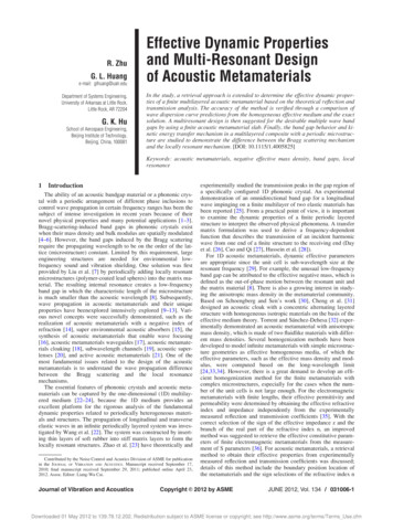
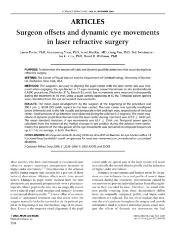
OFFSETS AND EYE MOVEMENTS IN LASER REFRACTIVE SURGERYpostoperative outcomes.11 However, a better understandingof the types of eye movements that occur during refractivesurgery procedures is needed because these movementslargely dictate the requirements of any eye-tracker (suchas its closed-loop bandwidth and sampling frequency)used to compensate for changes in eye location.Two types of eye movements relevant to refractive surgery procedures are torsional and fixational movements.Cyclotorsional eye movements can occur during fixationwhen the head is laterally tilted from the upright, verticalmeridian.12 Positionally induced cyclotorsion could resultin misregistration and rotation of a conventional or customized treatment because aberrations and Phoropter refractions are measured with the patient in an uprightposition, whereas treatments are performed monocularlywith the patient in a supine position. Most findings suggestthat cyclotorsional movements between an upright and supine state are not large and would not dramatically affecta refractive surgical procedure.13–15Fixational movements consist of tremor; microsaccades; and large, slow drifts in eye position.16 Very fewpublications have reported horizontal and vertical eyemovements in fixating patients during laser refractive surgery. In addition, the natural history of eye movements during refractive surgery has not been well documented.Schwiegerling and Snyder17 recorded eye movements in5 patients during laser in situ keratomileusis (LASIK) (ata rate of 30 Hz) and found a standard deviation in pupil decentration of approximately 0.10 mm across all eyes. Unfortunately, neither the temporal frequencies nor theAccepted for publication January 27, 2005.From the Center for Visual Science (Porter, Pan, Twietmeyer, Williams), University of Rochester, the Department of Ophthalmology (Yoon, MacRae), University of Rochester, and Bausch &Lomb (Cox), Rochester, New York, USA.Supported by National Institutes of Health grants EY014999,EY01319, EY07125, and EY04367, and research grants fromBausch & Lomb and Research to Prevent Blindness. Also supported in part by the National Science Foundation Science andTechnology Center for Adaptive Optics, managed by the University of California at Santa Cruz under cooperative agreement No.AST-9876783.Drs. Porter, Yoon, MacRae, and Williams have served as consultants to Bausch & Lomb. In addition, the University of Rochesterhas licensed intellectual property to Bausch & Lomb and has a research contract with them.Gary Gagarinas, Brenda Houtenbrink, Gina Crowley, MicheleComery, and Joseph Stamm gave technical assistance for thearticle.Reprint requests to Jason Porter, PhD, the Center for Visual Science, University of Rochester, Rochester, New York 14627.E-mail: jporter@cvs.rochester.edu.speeds of these movements were reported. It is importantto monitor fixation stability in patients as they receive theirlaser refractive surgery treatment. Fixational stability couldbe worse during LASIK than in normal conditions becauseLASIK patients are forced to fixate on the center of a lightblurred by a cornea that has received a flap cut and is beingablated. This altered surface could increase scatter in theeye and possibly decrease the patient’s fixational accuracy.Eye movements influence both the sampling rates andclosed-loop bandwidths of an eye-tracker and the amountof higher-order aberrations induced after surgery.We measured corneal decentrations caused by eyemovements in conventional LASIK procedures with aneye-tracker at a frequency equal to the repetition rate ofthe laser. The surgeon’s accuracy in aligning the center ofthe pupil with the laser system’s optical axis when engaging the eye-tracker was determined. We also computedthe temporal power spectrum of the measured eye movements to determine the necessary closed-loop bandwidthrequired of an eye-tracker to compensate for most cornealdecentrations in a conventional or customized procedure.PATIENTS AND METHODSSeventeen eyes of 9 normal patients were used to determinethe surgeon’s accuracy in centering the pupil with the laser system’s optical axis. The natural history of eye movements was measured during surgery in 10 of these eyes. All patients receivedconventional LASIK treatments from the same surgeon using theTechnolas 217z laser system (Bausch & Lomb) with an activeeye-tracker (120 Hz sampling rate). The mean attempted spherical refractive correction was 2.28 diopters (D) G 1.43 (SD)(range C0.25 to 4.15 D) and the mean attempted cylindricalcorrection, 0.47 G 0.45 D.A pupil camera was inserted into the laser system’s opticalpath to measure eye movements during the LASIK procedures.The camera was placed in a plane conjugate with the corneaand recorded images of the eye that were not altered by any eyetracker compensation. The frame rate of the pupil camera waselectrically synchronized with the repetition rate of the laser(50 Hz) such that an image of the eye was automatically obtainedevery time a pulse was fired. This method allowed precise determination of the location of the eye each time a laser pulse was delivered to the cornea. The pupil camera first recorded images ofthe laser’s aiming beam when coaligned with the system’s opticalaxis before surgery. Several circular marks were then created ona damp Chayet pad with a pen. The marked pad was placed onthe patient’s eye after the microkeratome incision was created,where it tightly adhered to the corneal surface and did not movethroughout the procedure. These marks were later used to trackeye movements during the ablation.Figure 1 illustrates the pad marks for 1 patient at the first andlast frames of the ablation. Any procedure in which the pad movedor was touched by the surgeon was eliminated from the study. Itwas verified that the pad did not move with respect to fixed features on the eye throughout the treatment. The variability in thedistances calculated between these fixed features and the markedspots on the pad during the entire ablation was on the same orderor less than the variability in the distances calculated between theJ CATARACT REFRACT SURG - VOL 31, NOVEMBER 20052059
OFFSETS AND EYE MOVEMENTS IN LASER REFRACTIVE SURGERYFigure 1. Surgical images of the same eye receiving a conventional LASIKtreatment when (A) the first pulse was fired and (B) the final laser pulsewas fired. The pad was marked with spots whose locations were referenced with respect to the center of the pupil from the first frame in A.These spots were used to track the eye as it moved during the procedure.A portion of the final laser pulse can be seen in B as it strikes the pad.marked spots alone. This indicates that the movement of the padon the eye was less than or approximately equal to our accuracy inmeasuring the movement of the spots on the pad for the entiretreatment.The pupil camera recorded the natural movement of each eyefor the entire ablation. The sequence of frames recorded duringthe treatment was processed after surgery using a custom-writtenMatlab program (The MathWorks, Inc.) to determine the torsional movements and horizontal and vertical translations for eacheye. To determine the surgeon’s accuracy in aligning the patient’spupil, the location of the laser system’s optical axis was obtainedfirst from the presurgical image of the laser’s aiming beam. Eachimage was analyzed 3 times using the custom-written Matlab program to determine the mean center location of the aiming beam.In this program, a small portion of the image containing the aiming beam was identified manually, and its center coordinates weredetermined using a center-of-mass algorithm. The repeatabilityfor locating the laser center coordinates, given by the mean acrossall images of the standard deviations of the 3 measurements, was4.6 mm (0.18 pixels).The location of the center of the pupil was determined fromthe first frame of the procedure (Figure 1, A). This pupil imagewas also analyzed 3 times using the Matlab program. A conventional edge-detection algorithm was used to find the edges of2060the pupil and a circle was fit to these edges using a nonlinearleast-squares technique.18 The pupil center coordinates were determined from the best-fit circle. The repeatability in determiningthe pupil center coordinates, given by the mean across eyes of thestandard deviations of the 3 measurements within an eye, was approximately 8.2 mm (0.32 pixels). These coordinates were compared with the laser center coordinates to determine thesurgeon’s accuracy in aligning the patient’s pupil with the lasersystem’s optical axis.When measuring eye movements, it was not possible totrack the edge of the pupil for the entire procedure. As shownin Figure 1, the ability to detect the pupil accurately deterioratedas the ablation progressed. The increased scatter observed inFigure 1, B, was primarily caused by an increase in corneal surface roughness and a decrease in corneal hydration. Therefore,the pad marks were used to track eye movements during theablation. First, a box was defined manually around each markedspot in the first recorded frame using our custom program. Thecentroid location of each spot was determined and then referenced with respect to the pupil center coordinates. Spots thatmoved outside the image owing to eye movements were not included in the analysis. The Matlab program cross-correlatedeach spot with its location in the following frame to determinethe relative shift of the selected spots between frames. Subpixelaccuracy was obtained by determining the center of mass foreach spot after the cross correlation with the new frame. Amean horizontal and vertical shift of the eye was computed foreach frame based on the shifts of the individual spots. This shiftwas then added to the previous offset between the pupil and laser center coordinates to determine the new location of the pupilcenter with respect to the laser system axis for each frame.The accuracy in determining the horizontal and verticalmovements was assessed by examining the variability in the distances calculated between all pairs of marked spots. This analysiswas also used to verify whether the pad moved during the treatment. Ideally, if the pad did not move, expand, or contract, the distance between each spot would remain the same across frames.The mean of the standard deviations of all distances between 2 analyzed spots was 7.1 G 1.94 mm and ranged between 3.7 and11.6 mm. This variability in distance was much smaller than asingle pixel on the pupil camera (1 pixel w 25.5 mm on theeye) and represents the accuracy of the program’s ability to detectthe center of mass locations of the spots. In procedures in whichthe pad moved, changes in the distances between spots were considerably larger than these calculated values (ie, typically greaterthan 51 mm or 2 pixels).In addition, the rotational movements of each eye during theablation were measured. To measure cyclotorsion, the customwritten Matlab program constructed a line connecting any 2 ofthe spots marked on the pad in 1 eye. The program then analyzedthe angle made between this line and the horizontal axis (ie,axis Z 0 degrees) for each frame in the treatment. (This procedurewas replicated for all possible combinations of spots in 1 eye before moving on to repeat the process in the other eyes.) Afterthe angles in each frame were measured, the amount the angleschanged for all possible line combinations between consecutiveframes were calculated and then the mean of these changes werecalculated to obtain a mean amount of rotation between frames.Across all eyes, the mean standard deviations of the cyclotorsionalmovement was 0.22 G 0.08 degrees and ranged between 0.09 degrees and 0.43 degrees. The range of rotation observed during thetreatment, calculated as the difference between the maximum andminimum angles subtended by each line, was also determined forJ CATARACT REFRACT SURG - VOL 31, NOVEMBER 2005
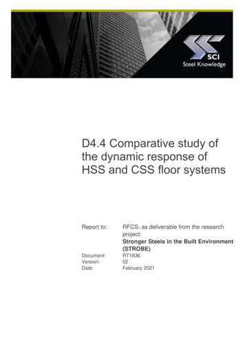
OFFSETS AND EYE MOVEMENTS IN LASER REFRACTIVE SURGERYeach eye. The mean across all eyes of the range of torsion was1.22 G 0.38 degrees and varied between 0.55 degrees and 1.96 degrees. This implies that none of the analyzed eyes experienced torsional movements in excess of 2 degrees.The amount of astigmatism induced when an astigmatic correction is applied at a fixed rotated angle, A, was calculated. In thiscase, the eye is rotated to the maximum extent at the very beginning of the procedure and remains in that position for the entireablation. These calculations represent an upper bound to theamount of astigmatism that can be induced by a fixed torsionalmovement. The wave aberration for an eye with only astigmatism,WAo(r,q), ispffiffiffi 2pffiffiffið1Þ6r sin 2qCC22 6r2 cos 2qWAo ðr; qÞZC 222where C 22 and C2 are the Zernike coefficients for astigmatism.The wave aberration for astigmatism rotated by A degrees,WAr(r,q), ispffiffiffi 2pffiffiffi6r sin½2ðqCAÞ CC22 6r2 cos½2ðqCAÞ WAr ðr; qÞZC 2p2ffiffiffi 22WAr ðr; qÞZ 6r f½C 22 cos 2A C2 sin 2A sin 2q2C½C 2ð2Þ2 sin 2ACC2 cos 2A cos 2qgThe residual wave aberration, WAR(r,q), after treating theoriginal astigmatic wavefront, WAo(r,q), with the rotated astigmatic wavefront, WAr(r,q), isWAR ðr; qÞZWAo ðr; qÞ WAr ðr; qÞpffiffiffi 22WAR ðr; qÞZ 6r2 f½C 22 C2 cos 2ACC2 sin 2A sin 2q2 22C½C2 C2 sin 2A C2 cos 2A cos 2qgFigure 2 illustrates the magnitude of astigmatism remainingafter an astigmatic correction applied at the minimum, mean,and maximum angles of torsional rotation measured in theseeyes as a function of the original amount of astigmatism. The largest attempted cylindrical correction in this group of patients was 1.25 D, and the largest range of torsion was 1.96 degrees. A patient with a cylindrical error of 1.25 D (Zernike astigmatism coefficient w 1.15 mm, 6 mm pupil) would theoretically haveapproximately 0.09 D of cylinder (Zernike astigmatism coefficient w 0.079 mm, 6 mm pupil) after an astigmatic correctionthat was statically rotated by 1.96 degrees. Because this amountof residual astigmatism is small and represents a worst-casescenario for correcting cylinder in our most astigmatic patient,cyclotorsional movements were not included in subsequentcalculations.The temporal power spectra of the horizontal and verticalchanges in eye position were calculated to determine the temporal frequency below which most eye movements occurred. Thetemporal power spectrum succinctly quantifies the size and speedof eye movements that occur at different frequencies. Fast eyemovements changing rapidly in time (ie, some saccades) arerepresented as high temporal frequencies, whereas slow eyemovements correspond to lower temporal frequencies. Smallamplitude eye movements have low power, whereas eye movements with large amplitudes (or large amounts of movement)have high power.RESULTSð3ÞThis expression for the residual wavefront may also be written aspffiffiffi 2 WAR ðr; qÞZ 6r2 fC 2ð4Þ2 sin 2qCC2 cos 2qgPupil and Laser Center AlignmentFigure 3 illustrates the surgeon’s accuracy in aligningthe center of the patient’s pupil with the central laser axiswhere 2 22C 22 ZC2 C2 cos 2ACC2 sin 2A2 2 22C2 ZC2 C2 sin 2A C2 cos 2A ð5Þ 2C 22 and C2 are the residual Zernike astigmatism coefficients. Forthe simple case in which the axis of the patient’s cylinder is oriented at 0 degrees or 90 degrees (ie, C 22 Z0), 222C 22 ZC2 sin 2A; C2 ZC2 ð1 cos 2AÞand the magnitude of residual astigmatism �ffiffiffiffiffiffiffiffiffiffiffiffiffiffiffiffi 222 2ðC 22 Þ CðC2 Þ Z2jC2 jjsin Ajð6ÞSimilarly, the magnitude of residual astigmatism when the patient’s cylindrical axis is located at 45 degrees or 135 degrees (ie,C22 Z0) �ffiffiffiffiffiffiffiffiffiffiffiffiffiffiffiffi 2 22 2ð7ÞðC 22 Þ CðC2 Þ Z2jC2 jjsin AjIn these 2 cases, the induced magnitude of astigmatism depends on the initial amount of astigmatism and the sine of the angle of rotation, A.Figure 2. Residual magnitude of astigmatism after applying an astigmaticcorrection that was rotated by the minimum (0.55 degrees, dashed-dotted line with squares), mean (1.22 degrees, solid line with circles), andmaximum (1.96 degrees, dashed line with diamonds) amount of torsionalrotation observed in these eyes. The residual astigmatism is plotted asa function of the original (or preoperative) amount of astigmatism forthe case when one of the Zerni
(LASIK) procedures (Technolas 217z; Bausch & Lomb). Eye movements were measured subsequently during the treatment in 10 eyes using a pupil camera operating at 50 Hz. Temporal power spectra were calculated from the eye movement measurements. RESULTS: The mean pupil misalignment by the surgeon at the beginning of the procedure was