Transcription
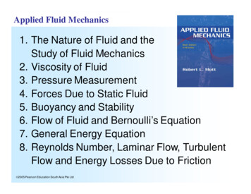
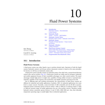
10Fluid Power Systems10.1IntroductionFluid Power Systems ElectrohydraulicControl Systems10.2Hydraulic FluidsDensity Viscosity Bulk Modulus10.3Hydraulic Control ValvesPrinciple of Valve Control Hydraulic Control Valves10.4Hydraulic PumpsPrinciples of Pump Operation Pump Controlsand Systems10.5Hydraulic CylindersCylinder ParametersQin Zhang10.6University of IllinoisCarroll E. GoeringUniversity of IllinoisFluid Power Systems ControlSystem Steady-State Characteristics System DynamicCharacteristics E/H System Feedforward-Plus-PIDControl E/H System Generic Fuzzy Control10.7Programmable Electrohydraulic Valves10.1 IntroductionFluid Power SystemsA fluid power system uses either liquid or gas to perform desired tasks. Operation of both the liquidsystems (hydraulic systems) and the gas systems (pneumatic systems) is based on the same principles.For brevity, we will focus on hydraulic systems only.A fluid power system typically consists of a hydraulic pump, a line relief valve, a proportional directioncontrol valve, and an actuator (Fig. 10.1). Fluid power systems are widely used on aerospace, industrial,and mobile equipment because of their remarkable advantages over other control systems. The majoradvantages include high power-to-weight ratio, capability of being stalled, reversed, or operated intermittently, capability of fast response and acceleration, and reliable operation and long service life.Due to differing tasks and working environments, the characteristics of fluid power systems aredifferent for industrial and mobile applications (Lambeck, 1983). In industrial applications, low noiselevel is a major concern. Normally, a noise level below 70 dB is desirable and over 80 dB is excessive.Industrial systems commonly operate in the low (below 7 MPa or 1000 psi) to moderate (below 21 MPaor 3000 psi) pressure range. In mobile applications, the size is the premier concern. Therefore, mobilehydraulic systems commonly operate between 14 and 35 MPa (2000–5000 psi). Also, their allowabletemperature operating range is usually higher than in industrial applications. 2002 CRC Press LLC
0066 frame C10 Page 2 Wednesday, January 9, 2002 4:10 PMFIGURE 10.1Schematic of a fluid power system.Electrohydraulic Control SystemsThe application of electronic controls to fluid power systems resulted in electrohydraulic control systems.Electrohydraulics has been widely used in aerospace, industrial, and mobile fluid power systems.Electrohydraulic controls have a few distinguishable advantages over other types of controls. First, anelectrohydraulic system can be operated over a wide speed range, and its speed can be controlled continuously. More importantly, an electrohydraulic system can be stalled or operated under very large acceleration without causing its components to be damaged. A hydraulic actuator can be used in strong magneticfield without having the electromagnetic effects degrade control performance. In addition, hydraulic fluidflow can transfer heat away from system components and lubricate all moving parts continuously.10.2 Hydraulic FluidsMany types of fluids, e.g., mineral oils, biodegradable oils, and water-based fluids, are used in fluid powersystems, depending on the task and the working environment. Ideally, hydraulic fluids should be inexpensive, noncorrosive, nontoxic, noninflammable, have good lubricity, and be stable in properties. Thetechnically important properties of hydraulic fluids include density, viscosity, and bulk modulus.DensityThe density, ρ, of a fluid is defined as its mass per unit volume (Welty et al., 1984).mr ---V(10.1)Density is approximately a linear function of pressure (P) and temperature (T) (Anderson, 1988).r r 0 ( 1 aP – bT )(10.2)In engineering practice, the manufacturers of the hydraulic fluids often provide the relative density(i.e., the specific gravity) instead of the actual density. The specific gravity of a fluid is the ratio of itsactual density to the density of water at the same temperature.ViscosityThe viscosity of a fluid is a measure of its resistance to deformation rate when subjected to a shearingforce (Welty et al., 1984). Manufacturers often provide two kinds of viscosity values, namely the dynamicviscosity ( µ) and the kinematic viscosity (ν). The dynamic viscosity is also named the absolute viscosity 2002 CRC Press LLC
0066 frame C10 Page 3 Wednesday, January 9, 2002 4:10 PMand is defined by the Newtonian shear stress equation:tm --dv(10.3)-----dywhere dv is the relative velocity between two parallel layers dy apart, and τ is the shear stress.The kinematic viscosity is the ratio of the dynamic viscosity to the density of the fluid and is definedusing the following equation:mn --r(10.4)In the SI system, the unit of dynamic viscosity is Pascal-seconds (Pa s), and the unit of kinematic viscosity2is square meter per second (m /s). Both the dynamic and kinematic vary strongly with temperature.Bulk ModulusBulk modulus is a measure of the compressibility or the stiffness of a fluid. The basic definition of fluidbulk modulus is the fractional reduction in fluid volume corresponding to unit increase of appliedpressure, expressed using the following equation (McCloy and Martin, 1973): Pb – V ------- V (10.5)The bulk modulus can either be defined as the isothermal tangent bulk modulus if the compressibilityis measured under a constant temperature or as the isentropic tangent bulk modulus if the compressibilityis measured under constant entropy.In analyzing the dynamic behavior of a hydraulic system, the stiffness of the hydraulic container playsa very important role. An effective bulk modulus, b e , is often used to consider both the fluid’s compressibility, b f , and container stiffness, b c , at the same time (Watton, 1989).1 11---- ---- ---bf bcbe(10.6)10.3 Hydraulic Control ValvesPrinciple of Valve ControlIn a fluid power system, hydraulic control valves are used to control the pressure, flow rate, and flowdirection. There are many ways to define a hydraulic valve so that a given valve can be named differentlywhen it is used in different applications. Commonly, hydraulic valves can be classified based on theirfunctions, such as pressure, flow, and directional control valves, or based on their control mechanisms,such as on-off, servo, and proportional electrohydraulic valves, or based on their structures, such asspool, poppet, and needle valves.A hydraulic valve controls a fluid power system by opening and closing the flow-passing area of the valve.Such an adjustable flow-passing area is often described using an orifice area, Ao , in engineering practice.Physically, an orifice is a controllable hydraulic resistance, Rh. Under steady-state conditions, a hydraulicresistance can be defined as a ratio of pressure drop, p , across the valve to the flow rate, q, through the valve.d ( p )R h --------------dq(10.7)Control valves make use of many configurations of orifice to realize various hydraulic resistance characteristics for different applications. Therefore, it is essential to determine the relationship between the 2002 CRC Press LLC
Discharge Coefficient0066 frame C10 Page 4 Wednesday, January 9, 2002 4:10 PMSpool PositionFIGURE 10.2Discharge coefficient versus spool position in a spool valve.pressure drop and the flow rate across the orifice. An orifice equation (McCloy and Martin, 1973) is oftenused to describe this relationship.2q C d A o --- Pr(10.8)The pressure drop across the orifice is a system pressure loss in a fluid power system. In this equation,the orifice coefficient, Cd , plays an important role, and is normally determined experimentally. It hasbeen found that the orifice coefficient varies greatly with the spool position, but does not appear to varymuch with respect to the pressure drop across the orifice in a spool valve (Fig. 10.2, Viall and Zhang,2000). Based on analytical results obtained from computational fluid dynamics simulations, the valvespool and sleeve geometries have little effect on the orifice coefficient for large spool displacements(Borghi et al., 1998).Hydraulic Control ValvesThere are many ways to classify hydraulic control valves. For instance, based on their structural configurations, hydraulic control valves can be grouped as cartridge valves and spool valves. This section willprovide mathematical models of hydraulic control valves based on their structural configurations.A typical cartridge valve has either a poppet or a ball to control the passing flow rate. Representingthe control characteristics of a cartridge valve without loss of generality, a poppet type cartridge is analyzed(Fig. 10.3).The control characteristics of a poppet type cartridge valve can be described using an orifice equationand a force balance equation. As shown in Fig. 10.3, the valve opens by lifting the poppet. Because ofthe cone structure of the poppet, the flow-passing area can be determined using the following equation:A x pdx sin a(10.9)Therefore, the passing flow can be calculated using the orifice equation. For a poppet type valve, it isrecommended to use a relative higher orifice coefficient of cd 0.77 0.82 (Li et al., 2000).2q c d A x --- ( P B – P A )r(10.10)The forces acting on the poppet include the pressure, spring, and hydraulic forces. The pressure forcecan be determined based on the upstream, downstream, and spring chamber pressures.2222pdp(D – d )pDF P P A -------- P B ------------------------- – P C --------444 2002 CRC Press LLC(10.11)
0066 frame C10 Page 5 Wednesday, January 9, 2002 4:10 PMPCDPBxPAdFIGURE 10.3Operation principle of a puppet type cartridge valve.The spring force biases the poppet towards closing. When the poppet is in the closed position, thespring force reaches its minimum value. The force increases as the poppet lifts to open the flow passage.FS k ( x0 x )(10.12)The steady-state flow force tends to open the poppet in this valve. The flow force is a function of theflow rate and fluid velocity passing through the valve orifice.F F rqv cos a(10.13)The flow control characteristics of a spool valve are similar to those of a cartridge valve and can bedescribed using an orifice equation. The only difference is that spool valve flow-passing area is determinedby its wet perimeter, w, and spool displacement, x.2q c d w x --- Pr(10.14)If the orifice is formed by the edge of the spool and the valve body, the wet perimeter is w πd. If theorifice is formed by n slots cut on the spool and the perimeter of each slot is n, the corresponding wetperimeter is w nb. The orifice coefficient for a spool valve normally uses cd 0.60 0.65.The forces acting on the spool also include the pressure, spring, and flow forces (Merritt, 1967). Thepressure force is either balanced on the spool, because of its symmetric structure in a direct-actuatorvalve (actuated by a solenoid directly), or the pressure force to actuate the spool movement in a pilotactuated valve. The spring force tends to keep the spool in the central (neutral) position and can bedescribed using Eq. (10.12). The flow forces acting on the spool can be calculated using Eq. (10.14). Theflow velocity angle, α , is normally taken as 69 .10.4 Hydraulic PumpsPrinciples of Pump OperationThe pump is one of the most important components in a hydraulic system because it supplies hydraulicflow to the system. Driven by a prime mover, a hydraulic pump takes the fluid in at atmospheric pressureto fill an expanding volume of space inside the pump through an inlet port and delivers pressurized 2002 CRC Press LLC
0066 frame C10 Page 6 Wednesday, January 9, 2002 4:10 PMfluids to the outlet due to the reduction in internal volume near the output port. The pump capacity isdetermined by pump displacement (D) and operating speed (n). The displacement of a pump is definedas the theoretical volume of fluid that can be delivered in one complete revolution of the pump shaft.Q Dn(10.15)The pump output pressure is determined by the system load, which is the combined resistance tofluid flow in the pipeline and the resistance to move an external load. Unless the pump flow hasegress either by moving a load or by passing through a relief valve back to the reservoir, excessivepressure build-up can cause serious damage to the pump and/or the connecting pipeline (Reed andLarman, 1985).Based on their ability to change displacement, hydraulic pumps can be categorized as fixed-flow orvariable-flow pumps. Based on their design, hydraulic pumps can be categorized as gear pumps, vanepumps, and piston pumps. Normally, gear pumps are fixed-flow pumps, and vane pumps and pistonpumps can be either fixed-flow pumps or variable-flow pumps.The choice of pump design varies from industry to industry. For example, the machine tool manufacturers often select vane pumps because of their low noise, and their capability to deliver a variableflow at a constant pressure. Mobile equipment manufacturers like to use piston pumps due to their highpower-to-weight ratio. Some agricultural equipment manufacturers prefer gear pumps for their low costand robustness (Reed and Larman, 1985), but piston pumps are also popular.Pump Controls and SystemsPumps are energy conversion devices that convert mechanical energy into fluid potential energy to drivevarious hydraulic actuators to do work. To meet the requirements of different applications, there aremany types of fluid power system controls from which to choose. The design of the directional controlvalve must be compatible with the pump design. Normally, an open-center directional control valve isused with a fixed displacement pump and a closed-center directional control valve is used in a circuitequipped with a variable displacement pump.A fluid power system including a fixed displacement pump and an open-center directional controlvalve (Fig. 10.1) is an open-loop open-center system. Such a system is also called a load-sensitive systembecause the pump delivers only the pressure required to move the load, plus the pressure drop to overcomeline losses. The open-loop open-center system is suitable for simple “on-off ” controls. In such operations,the hydraulic actuator either moves the load at the maximum velocity or remains stationary with thepump unloaded. If a proportional valve is used, the open-loop open-center system can also achievevelocity control of the actuator. However, such control will increase the pressure of the extra flow forreleasing it back to the tank. Such control causes significant power loss and results in low system efficiencyand heat generation.To solve this problem, an open-loop closed-center circuit is constructed using a variable displacementpump and a closed-center directional control valve. Because a variable displacement pump is commonlyequipped with a pressure-limiting control or “pressure compensator,” the pump displacement will beautomatically increased or decreased as the system pressure decreases or increases. If the meteringposition of the directional control valve is used to control the actuator velocity, constant velocity canbe achieved if the load is constant. However, if the load is changing, the “pressure-compensating” systemwill not be able to keep a constant velocity without adjusting the metering position of the control valve.To solve this problem, a “load-sensing” pump should be selected for keeping a constant velocity underchanging load. The reason for a “load-sensing” pump being able to maintain a constant velocity forany valve-metering position is that it maintains a constant pressure drop across the metering orifice ofthe directional control valve, and automatically adjusts the pump outlet pressure to compensate for thechanges in pressure caused by external load. The constant pressure drop across the valve maintainsconstant flow, and therefore, constant load velocity. 2002 CRC Press LLC
0066 frame C10 Page 7 Wednesday, January 9, 2002 4:10 PM10.5 Hydraulic CylindersA hydraulic cylinder transfers the potential energy of the pressurized fluid into mechanical energy todrive the operating device performing linear motions and is the most common actuator used in hydraulicsystems. A hydraulic cylinder consists of a cylinder body, a piston, a rod, and seals. Based on theirstructure, hydraulic cylinders can be classified as single acting (applying force in one direction only),double acting (exerts force in either direction), single rod (does not have a rod at the cap side), anddouble rod (has a rod at both sides of the piston) cylinders.Cylinder ParametersA hydraulic cylinder transfers energy by converting the flow rate and pressure into the force and velocity.The velocity and the force from a double-acting double-rod cylinder can be determined using thefollowing equations:4qv ------------------------22p(D – d )(10.16)p 22F --- ( D – d ) ( P 1 – P 2 )4(10.17)The velocity and the force from a double-acting single-rod cylinder should be determined differentlyfor extending and retracting motions. In retraction, the velocity can be determined using Eq. (10.16),and the force can be determined using the following equation:222p (D – d )pDF P 1 -------------------------- – P 2 --------44(10.18)In extension, the velocity and exerting forces can be determined using the following equations:4qv ---------2pD(10.19)22pDpdF ( P 1 – P 2 ) ---------- P 2 -------44(10.20)The hydraulic stiffness, kh , of the cylinder plays an important role in the dynamic performance of ahydraulic system. It is a function of fluid bulk modulus ( β ), piston areas (A1, A2), cylinder chambervolumes (V1, V2 ), and the volume of hydraulic hoses connected to both chambers (VL1, VL2). For a doubleacting single-rod cylinder, the stiffness on both sides of the piston acts in parallel (Skinner and Long,1998). The total stiffness of the cylinder is given by the following equation:22A1A1 - ------------------k h b ------------------ V L1 V 1 V L2 V 2 (10.21)The natural frequency, ωn, of a hydraulic system is determined by the combined mass, m, of thecylinder and the load using the following equation:wn 2002 CRC Press LLCkh---m(10.22)
0066 frame C10 Page 8 Wednesday, January 9, 2002 4:10 PM10.6 Fluid Power Systems ControlSystem Steady-State CharacteristicsThe steady-state characteristics of a fluid power system determine loading performance, speed controlcapability, and the efficiency of the system. Modeling a hydraulic system without loss of generality, asystem consisting of an open-center four-way directional control valve and a single-rod double actingcylinder is used to analyze the steady-state characteristics of the system (Fig. 10.1). In this system, theorifice area of the cylinder-to-tank (C-T) port in the control valve is always larger than that of the pumpto-cylinder (P-C) port. Therefore, it is reasonable to assume that the P-C orifice controls the cylinderspeed during extension (Zhang, 2000).Based on Newton’s Law, the force balance on the piston is determined by the head-end chamber pressure,P1 , the head-end piston area, A1, the rod-end chamber pressure, P2, the rod-end piston area, A2, and theexternal load, F, when the friction and leakage are neglected.P1 A1 – P2 A2 F(10.23)If neglecting the line losses from actuator to reservoir, the rod-end pressure equals zero. Then, thehead-end pressure is determined by the external load to the system.FP 1 ----A1(10.24)In order to push the fluid passing the control valve and entering the head-end of the cylinder, thedischarge pressure, PP , of the hydraulic pump has to be higher than the cylinder chamber pressure.The difference between the pump discharge pressure and the cylinder chamber pressure is determinedby the hydraulic resistance across the control valve. Based on the orifice equation, the flow rate enteringthe cylinder head-end chamber is2q C d A o --- ( P P – P 1 )r(10.25)Using a control coefficient, K, to represent Cd and ρ , the cylinder speed can be described using thefollowing equation:KAFv ---------o P P – ----A1A1(10.26)Equation (10.13) describes the speed-load relationship of a hydraulic cylinder under a certain fluidpassing area (orifice area) of the control valve. Depicted in Fig. 10.4, the cylinder speed decreases as theexternal load applied to the cylinder increases. When there is no external load, the cylinder speed reachesa maximum. Conversely, when the external load researches the valve of F PP A1, then the cylinder willstall. The stall load is independent of the size of the fluid passing area in the valve. Such characteristicsof a fluid power system eliminate the potential of overloading, which makes it a safer power transmissionmethod.In system analysis, the speed stiffness, kv , is often used to describe the consistency of the cylinder speedunder changing system load (Li et al., 2000).2 ( PP A1 – F )1k v – ---- --------------------------- vv------ F 2002 CRC Press LLC(10.27)
0066 frame C10 Page 9 Wednesday, January 9, 2002 4:10 PMCylinder SpeedAO 3 AO 2 AO 1AO 3AO 2AO1FmaxExternal LoadFIGURE 10.4Hydraulic cylinder load-speed relationship under the same system pressure.Equation (10.27) indicates that the increase in speed stiffness can be achieved either by increasing thesystem pressure or the cylinder size, or by decreasing the speed.System Dynamic CharacteristicsTo analyze the dynamic characteristics of this hydraulic cylinder actuation system, one can use flowcontinuity and system momentum equations to model the cylinder motion. Neglecting system leakage,friction, and line loss, the following are the governing equations for the hydraulic system:dy V dPq kx P P – P 1 A 1 ----- -----1 --------1dt b dt(10.28)d2yP 1 A 1 m -------2- Fdt(10.29)To perform dynamic analysis on this hydraulic system, it is essential to derive its transfer functionbased on the above nonlinear equation, which can be obtained by taking the Laplace transform on thelinearized form of the above equations (Watton, 1989).1- s ------------- dF ( s )– ------- A 21 b A 21 k 3 R o dv ( s ) ------------------------V112------------------- ms 12 ms 2k1 Ki---------- di ( s )A1A1 bV1(10.30)A1 k2 RoMaking2wn A1 b----------,V1 m1mbz ------------- ------------2 ,2k 2 R o V 1 A 1andk1 KiK s --------A1Equation (10.30) can be represented as1 V----2 -----1 sA1 b -------- d F ( s )k 3 R o K s di ( s )dv ( s ) -------------------------------- – ----------------------------------------------1 2 2z1 2 2z------2 s ------ s 1------2 s ------ s 1wwwn 2002 CRC Press LLCnwn1n(10.31)
Based on the stability criterion for a second-order system, it should satisfy12z-----2 s 2 ------ s 1 0wnwn(10.32)The speed control coefficient, Ks , is the gain between the control signal current and the cylinder speed.A higher gain can increase the system sensitivity in speed control.E/H System Feedforward-Plus-PID ControlEquation (10.31) indicates that the speed control of a hydraulic cylinder is a third-order system. Itsdynamic behaviors are affected by spool valve characteristics, system pressure, and cylinder size. Therefore, it is a challenging job to realize accurate and smooth speed control on a hydraulic cylinder. Afeedforward plus proportional integral derivative (FPID) controller has proven capable of achieving highspeed control performance of a hydraulic cylinder (Zhang, 1999).An FPID controller consists of a feedforward loop and a PID loop (Fig. 10.5). The feedforward loop isdesigned to compensate for the nonlinearity of the hydraulic system, including the deadband of thesystem and the nonlinear flow gain of the control valve. It uses a feedforward gain to determine the basiccontrol input based on demand speed. This feedforward gain is scheduled based on the inverse valvetransform, which provides the steady-state control characteristics of the E/H valve in terms of cylinderspeed and control-current to valve PWM driver.The PID loop complements the feedforward control via the speed tracking error compensation. ThePID controller is developed based on the transfer function of the linearized system for the hydrauliccylinder speed control system.KIˆG ( s ) Ê K P ---s K D s Ë(10.33)The robustness of the FPID control was evaluated based on its performance and stability. Performancerobustness deals with unexpected external disturbances and stability robustness deals with internalstructural or parametric changes in the system. The design of this FPID controller was based on a worstcase scenario of system operating conditions in tuning both the PID gains and the feedforward gain.G F (s )GPID (s)G H (s )H C (s )FIGURE 10.5 Schematic block diagram of the feedforward-plus-PID controller. GF (s) is the feedforward gain,GPID(s) is the overall gain of the feedback PID controller, GH(s) is hydraulic system gain, and HC(s) is the sensor gain. 2002 CRC Press LLC
E/H System Generic Fuzzy ControlFuzzy control is an advanced control technology that can mimic a human’s operating strategy in controlling complex systems and can handle systems with uncertainty and nonlinearity (Pedrycz, 1993). Onecommon feature of fuzzy controllers is that most such controllers are designed based on natural languagecontrol laws. This feature makes it possible to design a generic controller for different plants if the controlof those plants can be described using the same natural language control laws (Zhang, 2001).The speed control on a hydraulic cylinder actually is achieved by regulating the supplied flow rate tothe cylinder. In different hydraulic systems, the size of the cylinder and the capability of hydraulic systemare usually different, but the control principles are very similar. Representing cylinder speed controloperation, using natural language without loss of generality, the control laws are the same for all systems:To have a fast motion, open the valve fully.To make a slow motion, keep the valve open a little.To hold the cylinder at its current position, return the valve to the center.To make a reverse motion, operate the valve to the other direction.This natural language model represents the general roles in controlling the cylinder speed via an E/Hcontrol valve on all hydraulic systems. The differences in system parameters on different systems can behandled by redefining the domain of the fuzzy variable, such as fully, a lot, and a little, using fuzzymembership functions (Passino and Yurkovich, 1998). This model provides the basis for designing ageneric fuzzy controller for E/H systems. The adoption of the generic controller on different systems canbe as easy as redefining the fuzzy membership function based on its system parameters.Figure 10.6 shows the block diagram of a generic fuzzy controller consisting of two input variablefuzzifiers, a control rule base, and a control command defuzzifier. The two input fuzzifiers were designedto convert real-valued input variables into linguistic variables with appropriate fuzzy memberships. Eachfuzzifier consists of a set of fuzzy membership functions defining the domain for each linguistic inputvariable. A real-valued input variable is normally converted into two linguistic values with associatedmemberships. The definitions of these fuzzy values play a critical role in the design of generic fuzzycontrollers and are commonly defined based upon hydraulic system parameters. The fuzzy controller usesfuzzy control rules to determine control actions according to typical behaviors in the speed control ofhydraulic cylinders. The control outputs are also linguistic values and associated with fuzzy memberships.For example, if the demanding speed is negative small (NS) and the error in speed was positive small(PS), the appropriate valve control action will be positive small (PS).The appropriate control actions were determined based on predefined control rules. Since each realvalued variable commonly maps into two fuzzy values, the fuzzy inference engine fires at least two controlrules containing these fuzzy values to determine the appropriate control action. Therefore, at least twoappropriate fuzzy-valued control actions will be selected. However, the E/H controller can only implementone specific real-value control command at a given time. It is necessary to convert multiple fuzzy-valuedcontrol commands into one real-valued control signal in this fuzzy RulesSignalDefuzzifierG H (s )H C (y )FIGURE 10.6 Block diagram of fuzzy E/H control system. The fuzzy controller consists of input variable fuzzifiers,control rules, and a signal defuzzifier. 2002 CRC Press LLC
0066 frame C10 Page 12 Wednesday, January 9, 2002 4:10 PMThe defuzzification process converts two or more fuzzy-valued outputs to one real-valued output.There are many defuzzification methods, such as center of gravity (COG) and center of area (COA),available for different applications (Passino and Yurkovich, 1998). By COA approach, the real-valuedcontrol signal, u, was determined by the domain and the memberships of the selected fuzzy controlcommands, µ(ui ), using the following equation:n i 1 u i m ( u i )duu ---------------------------------n i 1 m ( u i )du(10.34)The COA method naturally averages the domains of selected fuzzy control commands, and thus reducesthe sensitivity of the system to noise. The use of a COA approach increased the robustness and accuracyof the control.The performance of the fuzzy controller depends on the appropriation of domain definition for bothinput and output fuzzy variables. Properly defined fuzzy variables for a specific E/H system will improvethe stability, accuracy, and nonlinearity compensation of the fuzzy controller. Normally, a triangularfuzzy membership function, µFV , was defined by domain values of a i , a j , and ak , for each fuzzy value(FV) in the fuzzy controller.mA m NLa1 a1 a2m NMa1 a2 a3m NSa2
systems (hydraulic systems) and the gas systems (pneumatic systems) is based on the same principles. For brevity, we will focus on hydraulic systems only. A fluid power system typically consists of a hydraulic pump, a line relief valve, a proportional direction control valve, and an actuator (Fig. 10.1). Fluid power systems are widely used on .