Transcription
Chapter 2. Memory Addressing Today's microprocessors include several circuits to make memory managment bothmore efficient and more robustIn this chapter we study details on how 80x86 (IA-32) microprocessors addressmemory chips and how Linux uses the available addressing circuits. At the sametime. You will better understand the theory of paging You will learn how to research the implementation on other platformsThis is the first of three chapters related to memory management Chapter 8 discusses how the kernel allocates main memory to itself Chapter 9 considers how linear addresses are assigned to processes
2.1. Memory Addresses Programmers refer to a memory address as the way to access a memory cell. But whendealing with 80 x 86 microprocessors, we have to distinguish three kinds of addresses: Logical address: Included in the machine language instructions to specify the addressof an operand or of an instruction. embodies the well-known 80 x 86 segmented architecture.consists of a segment and an offsetLinear address (also known as virtual address): A single 32-bit unsigned integer can be used to address up to 4 GB usually represented in hexadecimal notation (from 0x00000000 to 0xffffffff)Physical address: Used to address memory cells in memory chips. They correspond to the electrical signals sent along the address pins of themicroprocessor to the memory bus.Physical addresses are represented as 32-bit or 36-bit unsigned integers.
Memory Managment Unit(MMU) Translation Protection
2.2. Segmentation in Hardware Starting with the 80286 model, Intel microprocessors perform address translation intwo different ways called real mode and protected mode.We'll focus in the next sections on address translation when protected mode isenabled.Real mode exists mostly to maintain processor compatibility with older modelsand to allow the operating system to bootstrap.
2.2.1. Segment Selectors andSegmentation Registers A logical address consists of two parts: a segment identifier and an offset thatspecifies the relative address within the segment.The segment identifier is a 16-bit field called the Segment Selector, while the offsetis a 32-bit field.To make it easy to retrieve segment selectors quickly, the processor providessegmentation registers whose only purpose is to hold Segment Selectors; theseregisters are called cs, ss, ds, es, fs, and gs.
Segmentation registers Three of the six segmentation registers have specific purposes: cs: The code segment register, which points to a segment containing programinstructionsss: The stack segment register, which points to a segment containing the currentprogram stackds: The data segment register, which points to a segment containing global and staticdataThe cs register has another important function: it includes a 2-bit field that specifies theCurrent Privilege Level (CPL) of the CPU. The value 0 denotes the highest privilegelevel, while the value 3 denotes the lowest one. Linux uses only levels 0 and 3, which are respectively called Kernel Mode and UserMode.
Selector and descriptor
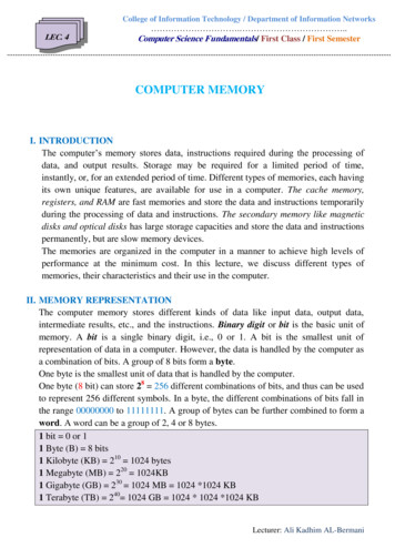
2.2.2. Segment Descriptors Each segment is represented by an 8-byte Segment Descriptor that describes thesegment characteristics.Segment Descriptors are stored either in the Global Descriptor Table (GDT ) or inthe Local Descriptor Table(LDT).Usually only one GDT is defined, while each process is permitted to have its ownLDT if it needs to create additional segments besides those stored in the GDT.The address and size of the GDT in main memory are contained in the gdtr controlregister, while the address and size of the currently used LDT are contained in theldtr control register.Figure 2-3 illustrates the format of a Segment Descriptor; the meaning of the variousfields is explained in Table 2-1.
Segment descriptor format
Table 2-1. Segment Descriptor field Base: Contains the linear address of the first byte of the segment.G: Granularity flag: if it is cleared (equal to 0), the segment size is expressed in bytes; otherwise, itis expressed in multiples of 4096 bytes.Limit: Holds the offset of the last memory cell in the segment, thus binding the segment length.When G is set to 0, the size of a segment may vary between 1 byte and 1 MB; otherwise, it mayvary between 4 KB and 4 GB.S: System flag: if it is cleared, the segment is a system segment that stores critical data structuressuch as the Local Descriptor Table; otherwise, it is a normal code or data segment.Type: Characterizes the segment type and its access rights.DPL: Descriptor Privilege Level: used to restrict accesses to the segment. It represents theminimal CPU privilege level requested for accessing the segment. Therefore, a segment with itsDPL set to 0 is accessible only when the CPL is 0 that is, in Kernel Mode while a segment with itsDPL set to 3 is accessible with every CPL value.P: Segment-Present flag: is equal to 0 if the segment is not stored currently in main memory. Linuxalways sets this flag (bit 47) to 1, because it never swaps out whole segments to disk.D or B: Called D or B depending on whether the segment contains code or data. Its meaning isslightly different in the two cases, but it is basically set (equal to 1) if the addresses used assegment offsets are 32 bits long, and it is cleared if they are 16 bits long (see the Intel manual forfurther details).AVL: May be used by the operating system, but it is ignored by Linux.
Types of segments widelyused in Linux Code Segment Descriptor: Indicates that the Segment Descriptor refers to a codesegment; it may be included either in the GDT or in the LDT. The descriptor has the S flagset (non-system segment).Data Segment Descriptor: Indicates that the Segment Descriptor refers to a data segment;it may be included either in the GDT or in the LDT. The descriptor has the S flag set. Stacksegments are implemented by means of generic data segments.Task State Segment Descriptor (TSSD): Indicates that the Segment Descriptor refers to aTask State Segment (TSS) that is, a segment used to save the contents of the processorregisters (see the section "Task State Segment" in Chapter 3); it can appear only in theGDT. The corresponding Type field has the value 11 or 9, depending on whether thecorresponding process is currently executing on a CPU. The S flag of such descriptors is setto 0.Local Descriptor Table Descriptor (LDTD): Indicates that the Segment Descriptor refersto a segment containing an LDT; it can appear only in the GDT. The corresponding Typefield has the value 2. The S flag of such descriptors is set to 0. The next section shows how80 x 86 processors are able to decide whether a segment descriptor is stored in the GDT orin the LDT of the process.
Any Segment Selector includes threefields Index: Identifies the Segment Descriptor entry contained in the GDT or in the LDTTI: Table Indicator : specifies whether the Segment Descriptor is included in theGDT (TI 0) or in the LDT (TI 1).RPL: Requestor Privilege Level : specifies the Current Privilege Level of the CPU when thecorresponding Segment Selector is loaded into the cs register; it also may be used toselectively weaken the processor privilege level when accessing data segments (see Inteldocumentation for details).
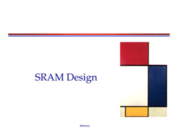
2.2.4. Segmentation Unit Figure 2-5 shows in detail how a logical address is translated into a correspondinglinear address. The segmentation unit performs the following operations: Examines the TI field of the Segment Selector to determine which DescriptorTable stores the Segment Descriptor. This field indicates that the Descriptor iseither in the GDT (in which case the segmentation unit gets the base linearaddress of the GDT from the gdtr register) or in the active LDT (in which case thesegmentation unit gets the base linear address of that LDT from the ldtr register).Computes the address of the Segment Descriptor from the index field of theSegment Selector. The index field is multiplied by 8 (the size of a SegmentDescriptor), and the result is added to the content of the gdtr or ldtr register.Adds the offset of the logical address to the Base field of the SegmentDescriptor, thus obtaining the linear address.Notice that, thanks to the nonprogrammable registers associated with thesegmentation registers, the first two operations need to be performed only when asegmentation register has been changed.
Translating a logical address
2.3. Segmentation in Linux Linux uses segmentation in a very limited way.In fact, segmentation and paging are somewhat redundant, because both can beused to separate the physical address spaces of processes: segmentation can assign a different linear address space to each process,while paging can map the same linear address space into different physicaladdress spaces.Linux prefers paging to segmentation for the following reasons: Memory management is simpler when all processes use the same segmentregister values that is, when they share the same set of linear addresses.One of the design objectives of Linux is portability to a wide range ofarchitectures; RISC architectures in particular have limited support forsegmentation.
Memory managment models
Use of segment registers insegmented memory model
Use of segment registers inflat memory model
Code and data segmentsused by Linux The 2.6 version of Linux uses segmentation only when required by the 80 x 86 architecture.All Linux processes running in User Mode use the same pair of segments to addressinstructions and data. These segments are called user code segment and user datasegment , respectively.Similarly, all Linux processes running in Kernel Mode use the same pair of segments toaddress instructions and data: they are called kernel code segment and kernel datasegment , respectively.Table 2-3 shows the values of the Segment Descriptor fields for these four crucialsegments.SegmentGLimitSTypeDPLD/BPuser code 0x0000000010xfffff110311user data0x0000000010xfffff12311kernel code 0x0000000010xfffff110011kernel data 0x0000000010xfffff12011 BaseBesides the four segments just described, Linux makes use of a few other specializedsegments. We'll introduce them in the next section while describing the Linux GDT.
Code and data segmentsused by Linux The corresponding Segment Selectors are defined by the macros USER CS,USER DS, KERNEL CS, and KERNEL DS, respectively. To address the kernelcode segment, for instance, the kernel just loads the value yielded by the KERNEL CSmacro into the cs segmentation register.Notice that the linear addresses associated with such segments all start at 0 and reach theaddressing limit of 2 32 -1. This means that all processes, either in User Mode or inKernel Mode, may use the same logical addresses.Another important consequence of having all segments start at 0x00000000 is that in Linux,logical addresses coincide with linear addresses; that is, the value of the Offset field of alogical address always coincides with the value of the corresponding linear address.
2.3.1 The Linux GDT In uniprocessor systems there is only one GDT, while in multiprocessor systemsthere is one GDT for every CPU in the system.All GDTs are stored in the cpu gdt table array, while the addresses and sizes of theGDTs (used when initializing the gdtr registers) are stored in the cpu gdt descrarray.The layout of the GDTs is shown schematically in Figure 2-6. Each GDT includes 18segment descriptors and 14 null, unused, or reserved entries.Unused entries are inserted on purpose so that Segment Descriptors usuallyaccessed together are kept in the same 32-byte line of the hardware cacheAll copies of the GDT store identical entries, except for a few cases. First, each processor has its own TSS segment, thus the correspondingGDT's entries differ.Moreover, a few entries in the GDT may depend on the process that the CPU isexecuting (LDT and TLS Segment Descriptors).Finally, in some cases a processor may temporarily modify an entry in its copy ofthe GDT; this happens, for instance, when invoking an APM's BIOS procedure.
Linux GDT
2.4 Paging in Hardware The paging unit translates linear addresses into physical ones.One key task in the unit is to check the requested access type against the accessrights of the linear address. If the memory access is not valid, it generates a PageFault exception (see Chapter 4 and Chapter 8).For the sake of efficiency, linear addresses are grouped in fixed-length intervalscalled pages ; contiguous linear addresses within a page are mapped intocontiguous physical addresses.In this way, the kernel can specify the physical address and the access rights ofa page instead of those of all the linear addresses included in it. Following the usualconvention, we shall use the term "page" to refer both to a set of linear addressesand to the data contained in this group of addresses.The paging unit thinks of all RAM as partitioned into fixed-length page frames(sometimes referred to as physical pages ). Each page frame contains a page that is, the length of a page frame coincideswith that of a page.A page frame is a constituent of main memory, and hence it is a storage area. Itis important to distinguish a page from a page frame; the former is just ablock of data, which may be stored in any page frame or on disk.
Paging in Hardware The data structures that map linear to physical addresses are called page tables ;they are stored in main memory and must be properly initialized by the kernelbefore enabling the paging unit.Starting with the 80386, all 80 x 86 processors support paging; it is enabled by settingthe PG flag of a control register named cr0 .When PG 0, linear addresses are interpreted as physical addresses.
2.4.1. Regular Paging Starting with the 80386, the paging unit of Intel processors handles 4 KB pages. The 32 bits of a linear address are divided into three fields: Directory: The most significant 10 bits Table: The intermediate 10 bits Offset: The least significant 12 bitsThe translation of linear addresses is accomplished in two steps, each based on a type oftranslation table. The first translation table is called the Page Directory, and the second iscalled the Page Table.(In the discussion that follows, the lowercase "page table" term denotes any page storingthe mapping between linear and physical addresses, while the capitalized "Page Table"term denotes a page in the last level of page tables.)
multilevel page tables If a simple one-level Page Table was used, then it would require up to 2 20 entries(i.e., at 4 bytes per entry, 4 MB of RAM) to represent the Page Table for eachprocess (if the process used a full 4 GB linear address space), even though aprocess does not use all addresses in that range.The two-level scheme reduces the memory by requiring Page Tables only forthose virtual memory regions actually used by a process.Each active process must have a Page Directory assigned to it. However, there is noneed to allocate RAM for all Page Tables of a process at once; it is more efficient toallocate RAM for a Page Table only when the process effectively needs it.The physical address of the Page Directory in use is stored in a control registernamed cr3 .The Directory field within the linear address determines the entry in the PageDirectory that points to the proper Page Table. The address's Table field, in turn,determines the entry in the Page Table that contains the physical address of the pageframe containing the page. The Offset field determines the relative position within thepage frame (see Figure 2-7). Because it is 12 bits long, each page consists of 4096bytes of data.
2 level paging
Entry fields Both the Directory and the Table fields are 10 bits long, so Page Directories andPage Tables can include up to 1,024 entries. It follows that a Page Directory canaddress up to 1024 x 1024 x 4096 2**32 memory cells, as you'd expect in 32-bitaddresses.The entries of Page Directories and Page Tables have the same structure. Eachentry includes the following fields: Present flag: If it is set, the referred-to page (or Page Table) is contained inmain memory; if the flag is 0, the page is not contained in main memory and theremaining entry bits may be used by the operating system for its own purposes. Ifthe entry of a Page Table or Page Directory needed to perform an addresstranslation has the Present flag cleared, the paging unit stores the linear addressin a control register named cr2 and generates exception 14: the Page Faultexception.Field containing the 20 most significant bits of a page frame physicaladdress: Because each page frame has a 4-KB capacity, its physical addressmust be a multiple of 4096, so the 12 least significant bits of the physical addressare always equal to 0. If the field refers to a Page Directory, the page framecontains a Page Table; if it refers to a Page Table, the page frame contains apage of data.
Paging in Hardware Accessed flag: Set each time the paging unit addresses the corresponding pageframe. This flag may be used by the operating system when selecting pages to beswapped out. The paging unit never resets this flag; this must be done by theoperating system.Dirty flag: Applies only to the Page Table entries. It is set each time a write operationis performed on the page frame. As with the Accessed flag, Dirty may be used by theoperating system when selecting pages to be swapped out. The paging unit neverresets this flag; this must be done by the operating system.Read/Write flag: Contains the access right (Read/Write or Read) of the page or ofthe Page Table (see the section "Hardware Protection Scheme" later in this chapter).User/Supervisor flag: Contains the privilege level required to access the page orPage Table (see the later section "Hardware Protection Scheme").PCD and PWT flags: Controls the way the page or Page Table is handled by thehardware cache (see the section "Hardware Cache" later in this chapter).Page Size flag: Applies only to Page Directory entries. If it is set, the entry refers to a2 MB- or 4 MB-long page frame (see the following sections).Global flag: Applies only to Page Table entries. This flag was introduced in thePentium Pro to prevent frequently used pages from being flushed from the TLB cache(see the section "Translation Lookaside Buffers (TLB)" later in this chapter). It worksonly if the Page Global Enable (PGE) flag of register cr4 is set.
2.4.2. Extended Paging Starting with the Pentium model, 80 x 86 microprocessors introduce extendedpaging, which allows page frames to be 4 MB instead of 4 KB in size.Extended paging is used to translate large contiguous linear address ranges intocorresponding physical ones; in these cases, the kernel can do withoutintermediate Page Tables and thus save memory and preserve TLB entries.As mentioned in the previous section, extended paging is enabled by setting thePage Size flag of a Page Directory entry. In this case, the paging unit divides the32 bits of a linear address into two fields: Directory: The most significant 10 bits Offset: The remaining 22 bitsPage Directory entries for extended paging are the same as for normal paging,except that: The Page Size flag must be set.Only the 10 most significant bits of the 20-bit physical address field aresignificant. This is because each physical address is aligned on a 4-MBboundary, so the 22 least significant bits of the address are 0.Extended paging coexists with regular paging; it is enabled by setting the PSEflag of the cr4 processor register.
Extended paging
2.4.3. Hardware Protection Scheme The paging unit uses a different protection scheme from the segmentation unit.While 80 x 86 processors allow four possible privilege levels to a segment, only twoprivilege levels are associated with pages and Page Tables, because privilegesare controlled by the User/Supervisor flag: When this flag is 0, the page can be addressed only when the CPL is less than 3(this means, for Linux, when the processor is in Kernel Mode).When the flag is 1, the page can always be addressed.Furthermore, instead of the three types of access rights (Read, Write, and Execute)associated with segments, only two types of access rights (Read and Write) areassociated with pages: If the Read/Write flag of a Page Directory or Page Table entry is equal to 0, thecorresponding Page Table or page can only be read;otherwise it can be read and written.Recent Intel Pentium 4 processors support an NX (No eXecute) flag in each 64bit Page Table entry.
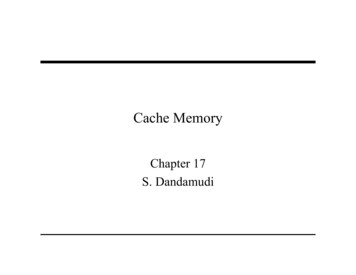
2.4.4. An Example of Regular Paging A simple example will help in clarifying how regular paging works. Let's assume thatthe kernel assigns the linear address space between 0x20000000 and 0x2003ffff to arunning process.This space consists of exactly 64 pages. We don't care about the physical addressesof the page frames containing the pages; in fact, some of them might not even be inmain memory. We are interested only in the remaining fields of the Page Tableentries.Let's start with the 10 most significant bits of the linear addresses assigned to theprocess, which are interpreted as the Directory field by the paging unit. The addresses start with a 2 followed by zeros, so the 10 bits all have the samevalue, namely 0x080 or 128 decimal. (binary: 0000 1000 0000)Thus the Directory field in all the addresses refers to the 129th entry of theprocess Page Directory. The corresponding entry must contain the physicaladdress of the Page Table assigned to the process (see Figure 2-9).If no other linear addresses are assigned to the process, all the remaining 1,023entries of the Page Directory are filled with zeros.The values assumed by the intermediate 10 bits, (that is, the values of the Tablefield) range from 0 to 0x03f, or from 0 to 63 decimal. Thus, only the first 64 entries ofthe Page Table are valid. The remaining 960 entries are filled with zeros.
An example of paging
An example of paging Suppose that the process needs to read the byte at linear address 0x20021406. Thisaddress is handled by the paging unit as follows: The Directory field 0x80 is used to select entry 0x80 of the Page Directory, whichpoints to the Page Table associated with the process's pages.The Table field 0x21 is used to select entry 0x21 of the Page Table, which pointsto the page frame containing the desired page.Finally, the Offset field 0x406 is used to select the byte at offset 0x406 in thedesired page frame.If the Present flag of the 0x21 entry of the Page Table is cleared, the page is notpresent in main memory; in this case, the paging unit issues a Page Fault exceptionwhile translating the linear address.The same exception is issued whenever the process attempts to access linearaddresses outside of the interval delimited by 0x20000000 and 0x2003ffff,because the Page Table entries not assigned to the process are filled with zeros; inparticular, their Present flags are all cleared.
2.4.5. The Physical Address Extension (PAE)Paging Mechanism The amount of RAM supported by a processor is limited by the number of address pinsconnected to the address bus. Older Intel processors from the 80386 to the Pentiumused 32-bit physical addresses. In theory, up to 4 GB of RAM could be installed onsuch systems; in practice, due to the linear address space requirements of User Modeprocesses, the kernel cannot directly address more than 1 GB of RAM, as wewill see in the later section "Paging in Linux."However, big servers that need to run hundreds or thousands of processes at thesame time require more than 4 GB of RAM.Intel has satisfied these requests by increasing the number of address pins on itsprocessors from 32 to 36. Starting with the Pentium Pro, all Intel processors arenow able to address up to 2**36 64 GB of RAM.With the Pentium Pro processor, Intel introduced a mechanism called PhysicalAddress Extension (PAE).
PAE PAE is activated by setting the Physical Address Extension (PAE) flag in the cr4control register.Intel has changed the paging mechanism in order to support PAE. The 64 GB of RAM are split into 2**24 distinct page frames, and the physicaladdress field of Page Table entries has been expanded from 20 to 24 bits.Because a PAE Page Table entry must include the 12 flag bits (described in theearlier section "Regular Paging") and the 24 physical address bits, for a grandtotal of 36, the Page Table entry size has been doubled from 32 bits to 64bits. As a result, a 4-KB PAE Page Table includes 512 entries instead of1,024.A new level of Page Table called the Page Directory Pointer Table (PDPT)consisting of four 64-bit entries has been introduced.The cr3 control register contains a 27-bit Page Directory Pointer Table baseaddress field. Because PDPTs are stored in the first 4 GB of RAM and alignedto a multiple of 32 bytes (2**5), 27 bits are sufficient to represent the baseaddress of such tables.The Page Size (PS) flag in the page directory entry enables large page sizes (2 MBwhen PAE is enabled).
PAE When mapping linear addresses to 4 KB pages (PS flag cleared in Page Directoryentry), the 32 bits of a linear address are interpreted in the following way: cr3: Points to a PDPT bits 31-30: Point to 1 of 4 possible entries in PDPT bits 29-21: Point to 1 of 512 possible entries in Page Directory bits 20-12: Point to 1 of 512 possible entries in Page Table bits 11-0: Offset of 4-KB pageWhen mapping linear addresses to 2-MB pages (PS flag set in Page Directoryentry), the 32 bits of a linear address are interpreted in the following way: cr3: Points to a PDPT bits 31-30: Point to 1 of 4 possible entries in PDPT bits 29-21: Point to 1 of 512 possible entries in Page Directory bits 20-0: Offset of 2-MB page
To summarize Once cr3 is set, it is possible to address up to 4 GB of RAM. If we want to addressmore RAM, we'll have to put a new value in cr3 or change the content of the PDPT.However, the main problem with PAE is that linear addresses are still 32 bitslong. This forces kernel programmers to reuse the same linear addresses tomap different areas of RAM.We'll sketch how Linux initializes Page Tables when PAE is enabled in the latersection, "Final kernel Page Table when RAM size is more than 4096 MB."Clearly, PAE does not enlarge the linear address space of a process, because itdeals only with physical addresses. Furthermore, only the kernel can modify thepage tables of the processes, thus a process running in User Mode cannot use aphysical address space larger than 4 GB.On the other hand, PAE allows the kernel to exploit up to 64 GB of RAM, and thus toincrease significantly the number of processes in the system.
2.4.6. Paging for 64-bit Architectures The third level of paging present in 80 x 86 processors with PAE enabled has beenintroduced only to lower from 1024 to 512 the number of entries in the PageDirectory and Page Tables.This enlarges the Page Table entries from 32 bits to 64 bits so that they can storethe 24 most significant bits of the physical address.Two-level paging, however, is not suitable for computers that adopt a 64-bitarchitecture. Let's use a thought experiment to explain why: Start by assuming a standard page size of 4 KB. Because 1 KB covers a rangeof 2 10 addresses, 4 KB covers 2 12 addresses, so the Offset field is 12 bits.This leaves up to 52 bits of the linear address to be distributed between theTable and the Directory fields.If we now decide to use only 48 of the 64 bits for addressing (this restrictionleaves us with a comfortable 256 TB address space!), the remaining 48-12 36bits will have to be split among Table and the Directory fields.If we now decide to reserve 18 bits for each of these two fields, both the PageDirectory and the Page Tables of each process should include 2 18 entries thatis, more than 256,000 entries.
Paging levels in some 64-bit architectures All hardware paging systems for 64-bit processors make use of additional paging levels. Thenumber of levels used depends on the type of processor. Table 2-4 summarizes themain characteristics of the hardware paging systems used by some 64-bit platformssupported by Linux.PlatformPage sizeaddress bits usedpaging levelssplittingalpha8 Kb *43310 10 10 13ia644 KB *3939 9 9 12ppc644 KB41310 10 9 12sh644 KB41310 10 9 12x86 644 KB4849 9 9 9 12*This architecture supports different page sizes; we select a typical page size adopted by Linux As we will see in the section "Paging in Linux" later in this chapter, Linux succeeds inproviding a common paging model that fits most of the supported hardware pagingsystems.
2.4.7. Hardware Cache Today's microprocessors have clock rates of several gigahertz, while dynamic RAM(DRAM) chips have access times in the range of hundreds of clock cycles.This means that the CPU may be held back considerably while executing instructionsthat require fetching operands from RAM and/or storing results into RAM.Hardware cache memories were introduced to reduce the speed mismatch betweenCPU and RAM.They are based on the well-known locality principle , which holds both for programsand data structures.It therefore makes sense to introduce a smaller and faster memory that containsthe most recently used code and data.For this purpose, a new unit called the line was introduced into the 80 x 86architecture. It consists of a few dozen contiguous bytes that are transferred inburst mode between the slow DRAM and the fast on-chip static RAM (SRAM) usedto implement caches.
Hit and miss,write-through and write-back When accessing a RAM memory cell, the CPU extracts the subset index from the physicaladdress and compares the tags of all lines in the subset with the high-order bits of the physicaladdress. If a line with the same tag as the high-order bits of the address is found, the CPU hasa cache hit; otherwise, it has a ca
2.2.1. Segment Selectors and Segmentation Registers A logical address consists of two parts: a segment identifier and an offset that specifies the relative address within the segment. The segment identifier is a 16-bit field called the Segment Selector, while the offset is a 32-bit field. To make it easy to retrieve segment selectors quickly, the processor provides