Transcription
FINDFIND NEXTChapter6InstallationandConstructionLester H. Gabriel, Ph.D., P.E.
FINDFIND NEXT INSTALLATION AND CONSTRUCTIONThis chapter provides information on the handling and installation of corrugatedpolyethylene pipe and fittings in non-pressure applications including most sewers,culverts and subdrainage systems. All types of pipe, regardless of material, must beinstalled as specified to perform as expected.The Department of Labor, Occupational Safety and Health Administration (OSHA),Safety and Health Regulations for Construction requires observance of its safety andother guidelines during all phases of construction including foundation preparation,excavation, pipe handling, assembly and backfilling. Stricter requirements may berequired in some states and local jurisdictions.Additional guidelines for the installation of corrugated polyethylene pipe are locatedin the following standards: ASTM D 2321 – Standard Practice for Underground Installation of ThermoplasticPipe for Sewers and Other Gravity-Flow Applications CAN/CSA B182.11 – Recommended Practice for the Installation of ThermoplasticDrain, Storm and Sewer Pipe and Fittings AASHTO Section 30 – Thermoplastic PipeImportance of Good Installation PracticeThe structural design of a buried pipeline presumes the response to loads of a pipe/soil composite structure. Attention to detail on the part of the contractor, transporterand yard handler is essential to insure proper performance. Proper dimensionalcontrols of trench excavation, pipe laying and pipe joining are essential to the successof a project. Correct selection and compaction of the soils composing the pipe/soilenvelope are likely to dominate the structural performance of both pipe and soil.The desired constant pressure around the pipe and uniform support of the pipein the longitudinal direction cannot be achieved in the absence of good practice.ASTM D 2321, AASHTO Section 30 and CAN/CSA B182.11 define good practicesfor the installation of thermoplastic pipe. Each recommends proper techniques fortrench excavation, placement, bedding and backfill to assure the pipe performs wellduring its full service life. AASHTO Section 30 is narrowly focused on gravity flowhighway and airport drainage pipelines under pavements subjected to heavy wheelloads. Shallow burial is a major consideration. ASTM D 2321 is broadly focused onthe general class of gravity flow pipelines, which include both drainage and sanitaryfacilities. Non-trivial differences exist between the two specifications. Federal, state,county and city governments, or other agencies or organizations of jurisdiction, areCHAPTER 6: INSTALLATION AND CONSTRUCTION
FINDFIND NEXT responsible for setting the particular governing standards appropriate to the installationof interest. References to specifications in this chapter are not intended for use in allpipelines at all locations; they are intended only to serve as examples of good practices.Transportation, Handling and StorageThe contractor should conduct an inspection at the time of delivery to verify thatthe correct products and the expected quantities are received. Pipe walls and corrugations, gaskets, pipe ends, couplers or other joints, and accessories should be visuallyinspected for damage such as cuts, gouges, delamination, bulges, flat areas and ovalitythat may have occurred during shipment. Nominal pipe size, manufacturer’s name,date code and applicable standards generally are marked on the pipe.To prevent injury to construction personnel and damage to pipes, dropping and/orrolling of pipes during unloading and handling should be prevented. Refer to themanufacturer’s instructions for unloading of trucks, trailers and railcar platforms.Pipes 18 in. (450 mm) or less may be hand lifted and placed by two people. Largersizes require mechanical equipment; a minimum of two lifting slings of fabric orplastic, located at third points along the length, is preferred. (Metal chains and cablesare to be avoided.) Equipment such as loading booms or forklifts should not be usedsince they can damage the pipe. Pipe should never be dropped on the ground.Palletized pipe should remain on pallets for jobsite storage. Non-palletized pipe shouldbe stockpiled for temporary storage in a flat debris-free area clear of constructiontraffic. Do not remove tie-down straps or bands until the pipes have been secured.Pipes should be stockpiled on level ground and restricted to a stack height no greaterthan 6 ft. (2 m). To prevent rolling, blocking should be provided at approximatelythird points along the length. The removal of any one pipe should not cause shiftingor rolling of any of the remaining pipes. The pipe should be supported along itslength, avoiding concentrated loads along bell ends. Any protective covering ofgaskets should remain until the pipe is ready for installation; exposed gaskets shouldbe protected from dust and exposure to sunlight. Couplers and fittings should bestored flat to prevent distortion and damage. For pipe with attached bells, a commonstacking method is to alternate the direction of the pipe lengths so that the bells arenot stacked on each other. For smooth interior pipe, nesting smaller pipes insidelarger pipes can minimize the storage space. Factory installed gaskets on the spigotmay be protected by positioning them between pipe corrugations. Nesting corrugatedinterior pipe should only be done when the pipe can be easily removed. Extremesummer heat could affect the ovality or shape of some pipes. It is recommended thatproducts be rotated during storage to eliminate such deflection.CHAPTER 6: INSTALLATION AND CONSTRUCTION
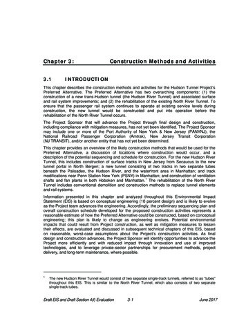
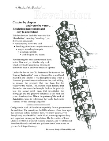
FINDFIND NEXT Trench ExcavationThe soil envelope of a pipe/soil composite structure will reflect the qualities of thenative materials beyond the trench walls containing the pipe. If the soil stiffnessbeyond the trench wall is stiffer than the expected stiffness of the compacted trenchfill, then the specified trench width is generally governed by that width necessary toinsure the prescribed compaction. For competent in-situ soil, wider than necessarytrench widths are not advised. Should the soil stiffness beyond the trench wall beless stiff and/or readily more compressible than the required trench fill, then thetrench width is often specified by the customer agency or organization to be widerthan usual (see ASTM D 2321). Success of the design of the installation depends,in part, upon realization of the geotechnical information describing the in-situ soilproperties. If, during the course of excavation, the soils or soil properties are notwhat were expected as noted in the contract, the organization responsible for designshould be informed. See Figure 6-1 for definitions of trench terms.Figure 6-1Figure 6-1: Trench TermsIn the absence of unusual conditions, and for purposes of guidance, the provisionsof ASTM D 2321 and CAN/CSA B182.11 are noted. According to ASTM D 2321,the trench width should be no wider than what is required to safely and convenientlycompact backfill material on either side of the pipe. Trench widths will reflect theselection of backfill material, ease of compacting backfill in the haunch zone (frompipe bottom to springline), compaction methods, pipe diameters and the width ofthe nearest larger size excavator bucket (for pipes of diameter 10 in. (250 mm) andCHAPTER 6: INSTALLATION AND CONSTRUCTION
FINDFIND NEXT smaller). In unsupported unstable soils, knowledge of the depth of cover, thestiffnesses of backfill and in-situ soils, and the size of the pipe are required fora determination of the trench width by the responsible engineer. AASHTOSection 30 requires a minimum trench width of not less than 1.5 times the pipeoutside diameter plus 12 in. (300 mm). ASTM D 2321 establishes trench widths asthe greater of either the pipe outside diameter plus 16 in. (400 mm) or 1.25 timesthe pipe outside diameter plus 12 in. (300 mm). See Table 6-1.Table 6-1Minimum Trench Width11AASHTO Sec 30Min. TrenchWidth in. (mm)ASTM D 2321Min. TrenchWidth in.(mm)Inside diameterin. (mm)Typical OutsideDiameter in. (mm)4 (100)5 (120)19 (480)21 (530)6 (150)7 (177)22 (570)23 (580)8 (200)9 (233)26 (650)25 (640)10 (250)11 (287)29 (740)27 (690)12 (300)14 (356)33 (840)30 (760)15 (375)18 (450)39 (980)34 (870)18 (450)21 (536)44 (1110)38 (970)21 (525)24 (622)49 (1240)43 (1080)24 (600)27 (699)53 (1350)46 (1180)30 (750)34 (866)63 (1600)55 (1390)36 (900)41 (1041)73 (1870)63 (1610)42 (1050)48 (1219)84 (2130)72 (1830)48 (1200)54 (1372)93 (2360)80 (2020)54 (1350)61 (1577)105 (2670)90 (2276)60 (1500)67 (1707)113 (2870)96 (2440)72 (1800)80 (2032)132 (3350)112 (2840)Also refer to manufacturer’s recommendationsCHAPTER 6: INSTALLATION AND CONSTRUCTION
FINDFIND NEXT For two, or more, parallel pipes in a common trench, properly compacted backfill isrequired between pipes. Minimum spacing between pipes may be satisfied by thefollowing (see Table 6-2):Table 6-2Minimum Spacing of Parallel Pipes in a Single TrenchNormal Diameter (D) in. (mm)Minimum Spacing in. (mm) 24 (600)12 (300) 24 (600)D/2Depending on the type of backfill, the compaction equipment and joining methods,these dimensions may need to be increased.Stable sidewalls are a requirement for all trench construction. Proper slopes forunbraced walls or appropriate bracing and shoring with sheeting or shields forvertical walls are required. As sheeting and shoring are removed, compaction ofmaterial in the void space must proceed with the removal of supports. Geotextiles,or filter fabrics, may be considered in areas where the native soil is very soft and/ormigrates easily. Geotextiles designed for strength and stability may help overcomesome of the structural deficiencies in soft native soils and allow reductions in trenchwidths. They may also be placed on the trench bottom and sides to separate nativesoils and backfill material. All trenches should be backfilled as soon as practicable,but not later than the end of each working day. Also, care should be taken to protectexcavated soil from collecting moisture while the trench is prepared and pipe is laid.Uniformity of the underlying soil that forms the trench bottom will avoid stressconcentrations and associated irregular pipe deformations. The condition of shortreaches of non-uniform in-situ soils may be remedied by compacting and levelingthe native soils. Alternatively, for the full width of the trench, the trench bottommay be over-excavated, often to a minimum depth of 6 in. (150 mm), and replacedwith a layer of properly compacted (as specified) imported material. This samealternative is appropriate for the condition of a trench bottom that initially includesthe occurrence of large protruding boulders. Where pipe segments are joined withprotruding features, such as the bells of bell and spigot joints, recesses constructedin the trench bottom, followed by hand compaction of backfill around the joint, willprovide continuous support and uniform bearing.CHAPTER 6: INSTALLATION AND CONSTRUCTION
FINDFIND NEXT Differential settlements may compromise the structural integrity of a buried pipe.Trench bottoms should be free of large stones, clumps of soil, frozen soil and debris;they should be slightly over excavated to allow for bedding material. If trench bottomshave less than ideal soil conditions, the preferred method is to remove the poor soiland replace it with soil that will provide predicable behavior. If replacement of thesoil is not possible, long reaches of soft-to-hard trench bottoms may be managed witha minimum of two short lengths of pipe with gasket joints that will accommodate thetendency of longitudinal pipe rotation in the transition zone. The use of long lengthsof pipe across the transition zone carries the risk of a pipe’s joints opening, or crosssectional distortion in response to unavoidable rotation.If unexpected deposits of soil that, when wetted, will settle rapidly (dry silts andsands of low density) or swell (expansive clays) are encountered, the contractor isadvised to contact the agency of jurisdiction for preferred strategies addressinganticipated problems. Alternatives may include removing the offending materialfollowed by recompaction of the original or higher quality soil, chemical stabilizationof the in-situ soil, and/or various schemes for protecting against the accumulationof water in the sensitive regions.Dry trench conditions are a prerequisite for proper placement and embedment ofdrainage pipe. Surface water draining towards the trench must be redirected. Waterin the trench during pipe installation can create a safety hazard. Maintenance of lineand grade is more difficult with a tendency for pipe flotation. Dewatering is requiredto minimize these disabilities and the likelihood of instability of trench walls andslopes. Ground water should not be permitted to rise above the trench bottom untilafter the installed pipe is fully bedded and enough fill is in place to prevent flotation.When well points are used to lower the ground water, adjacent areas and structuresmust be monitored to prevent damaging subsidence. Sheeting and shoring forvertical trench walls should not permit the seepage of water and soil in areas wheregroundwater is higher than the trench bottom. Any loss of fines due to seepage ordewatering is evidence that soil voids in the vicinity of the pipe are being created.To limit this type of damage to the pipe/soil composite structure, dewateringoperations must be monitored for the presence of a significant loss of fines.Laying and Joining of HDPE PipesPipe sections should be lowered into the trench without damage to the pipe or pipeends where couplings are to be made. Field cuts may be made with a handsaw orpower pipe cutoff saw. For pipes of annular corrugations, square cut only througha corrugation valley, never through a corrugation sidewall. Spirally corrugated pipeshould be cut with a cutting guide (a standard coupling is useful) or reference marksCHA
ASTM D 2321, AASHTO Section 30 and CAN/CSA B182.11 define good practices for the installation of thermoplastic pipe. Each recommends proper techniques for trench excavation, placement, bedding and backfill to assure the pipe performs well during its full service life. AASHTO Section 30 is narrowly focused on gravity flowFile Size: 385KBPage Count: 20