Transcription
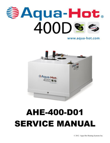
AHE-400-D01SERVICE MANUAL 2012 Aqua-Hot Heating Systems Inc.
03/2012 Aqua-Hot 400-D01 Hydronic Heating System Service Manual—Rev. D— Page 2 —
Table of ContentsSection 1: Introduction to the Aqua-Hot 400Introduction . .Page 6-7Danger, Warning, Caution, and Note Box Definitions. .Page 6Section 2: Aqua-Hot Hydronic Heating System OverviewTechnical Information . .Page 8I.D. Label Sample . .Page 9Component Overview .Page 9-11Aqua-Hot Operational Flow-Chart . .Page 12Antifreeze & Water Heating solution. .Page 13-14Section 3: Interior Switch PanelDiesel-Burner Switch . .Page 15Electric Element Switch . .Page 15Pin Label .Page 16-17Section 4: Exhaust System RequirementsExhaust System Requirements . .Page 18Section 5: Aqua-Hot 400 ComponentsInterlock Switch . .Page 19Fluid Level Sensor . .Page 20-21Control Thermostat.Page 21-22A.C. High Limit Thermostat . Page 23D.C. High Limit Thermostats . Page 24Low Temperature Cut-Off Thermostat .Page 25-26Check Valves .Page 26-27Tempering Valve .Page 28-29Circulation Pumps 1 & 2 .Page 29-31Stir Pump .Page 31-33Electric Heating Element .Page 34-35A.C. Relay . .Page 36Section 6: Electronic ControllerGeneral Facts . .Page 37Secondary 12 Volt DC battery Connection . .Page 38Terminal Strips with Screw-Type Fasteners . .Page 38Low Voltage Reset Feature . .Page 39Replacement Procedure . .Page 40Proper Jumper Pin Formation . .Page 40 03/2012 Aqua-Hot 400-D01 Hydronic Heating System Service Manual—Rev. D— Page 3 —
Table of ContentsSection 7: Electronic Controller Indicator LightsElectric Heating Element Status Indicator Light . Page 41Heating Zones Status Indicator Lights 1-5 . Page 41Low Battery Voltage Fault Indicator Light . Page 41Low Temp Cutoff Status Indicator Light . Page 41Low Tank-Level Cutoff Indicator Light . Page 41Heating Status Indicator Light . Page 41[Circulation] Pump #1 Indicator Light. Page 41-42[Circulation] Pump #2 Indicator Light. Page 42[Stir] Pump #2 Indicator Light . Page 42Diesel-Burner Status Indicator Light . Page 42Overload Fault Indicator Light . Page 42Section 8: Diesel-BurnerOverview . Page 43I.D. Plate . Page 43Diesel-Burner Overview . Page 44Diesel-Burner Operational Flow Chart . Page 45Diesel-Burner Operational Overview . Page 46-48Section 9: Detaching and Reattaching the Diesel-BurnerDetaching the Diesel-Burner . Page 49-51Reattaching the Diesel-Burner . Page 52-54Section 10: Diesel-Burner Components and Repair InformationDiesel-Burner Component Overview . Page 55Motor . Page 56-59Flame Sensor . Page 60-61Ignition Electrodes . Page 62-63Fuel Nozzle . Page 63-64Fuel Solenoid . Page 65Fuel Pump . Page 66-68Bearings . Page 69-71Ignition Coil . Page 72-73Controller . Page 74-75 03/2012 Aqua-Hot 400-D01 Hydronic Heating System Service Manual—Rev. D— Page 4 —
Table of ContentsSection 11: TroubleshootingIf the Aqua-Hot is Black Smoking . Page 76If the Aqua-Hot is Blue/White Smoking . Page 77If one of the Aqua-Hot’s Heating Zones will not get hot. Page 78If there is a lack of domestic continuous hot water . Page 79If there is antifreeze leaking . Page 80-81Appendix A: Wiring Diagram .Page 82-83Appendix C: Fuel Pressure check and Adjustment .Page 85-90Appendix D: Extreme Cold Weather Operation .Page 91-92Appendix E: Aqua-Hot Annual Maintenance .Page 93-106Appendix F: Winterization Process . Page 107Appendix G: Filling/Draining the Aqua-Hot .Page 108-111 03/2012 Aqua-Hot 400-D01 Hydronic Heating System Service Manual—Rev. D— Page 5 —
SECTION 1: INTRODUCTIONThis service and parts manual is designed to aidtrained and qualified service technicians withthe process of troubleshooting and servicing theAqua-Hot 400-D01 Hydronic heating system.The Aqua-Hot 400-D01 heating system features a 12 VoltDC powered diesel-burner and a 120 Volt-AC, 1650 Wattelectric heating element. These two heating sources are usedin conjunction with an FDA-approved “GRAS” (GenerallyRecognized as Safe) propylene glycol based boiler antifreezeand water heating solution in order to provide a continuoussupply of domestic hot water, interior/fresh water tank heating, independent interior zone heating, and engine preheating. Be sure to reference Figures 3 through 5 for a complete component overview.Please note that all Danger, Warning, Caution, and Note boxes, appearing as needed throughout this manual, must bereviewed and adhered to during any service procedure inorder to avoid potential hazards, which could result in injury,product damage, or property damage.Should additional assistance be needed, please contact thetechnical support department at 1-800-685-4298, Mondaythrough Friday, between the hours of 7:00 AM and 4:00 PMMountain Standard Time.Danger, Warning, Caution, and Note Boxes:Danger, Warning, Caution, and Note boxes appear throughout this manual as a means of alerting the service technicianto important information.INDICATES THAT PERSONAL INJURY IS LIKELY ORIMMINENT.Indicates that serious damage to the heater will occurand personal injury is possible as well.Indicates that damage to the heater is possible.NOTE: Indicates information that requires special attention by the service technicianTO THEAQUA-HOT 400-D01Understanding the Aqua-Hot 400-D01’s Major Systems:The basis for the Aqua-Hot heating system’s functionality isthe antifreeze and water heating solution, which is comprisedof water that is distilled, de-ionized, or soft, as well as FDAapproved “GRAS” propylene glycol based boiler antifreeze.Through this solution’s ability to maintain and transfer heat,the Aqua-Hot’s three major systems: the domestic watersystem, engine preheat system, and interior heating system,are able to function effectively. This antifreeze and waterheating solution is contained within the Aqua-Hot’s boilertank and is heated by the diesel-burner when its operatingcriteria are met and/or the electric heating element when itsoperating criteria are met. In order for the diesel-burner tobe considered as a heating source by the Aqua-Hot, it musthave an adequate fuel supply, receive power from the electronic controller, and be selected as a heating source from theinterior switch panel. In order for the electric heating element to be considered as a heating source by the Aqua-Hot,it must receive power from either a generator or from shorepower and be selected as a heating source from the interiorswitch panel. Once the antifreeze and water heating solutionachieves operating temperature (as determined by the AquaHot’s control thermostat), the domestic water system, theengine preheat system, and the interior heating system arepermitted to operate as needed.Domestic Hot Water Priority System:The Aqua-Hot 400 is a Hot Water Priority System. Meaning, that the Aqua-Hot 400 cannot heat the interior of themotor home, and produce continuous hot water simultaneously. When Domestic Hot Water is being used, the interiorheating system will shut down, until no more Domestic HotWater is called for.The domestic hot water priority system is responsible forproviding hot water whenever a hot water faucet is openedsuch as with a shower or sink.When hot water is requested, domestic water from the motorhome’s fresh water tank is transported through a copper coilin the Aqua-Hot’s boiler tank where heat is transferred fromthe heated antifreeze and water heating solution to the domestic water flowing through the copper coil. The heateddomestic water then flows through the tempering valve to bemixed with cool water from the fresh water tank to achievean appropriate temperature before it flows to the faucet requesting hot water. 03/2012 Aqua-Hot 400-D01 Hydronic Heating System Service Manual—Rev. D— Page 6 —
SECTION 1: INTRODUCTIONTO THE400-D01Interior Heating System:AC Circuit:The interior heating system is responsible for providing heatto the motor home’s interior in order to maintain the temperature at a comfortable level.For interior heating, it is the room thermostats that trigger theAqua-Hot’s interior heating system. When a thermostat recognizes that heat is required in a particular area, it sends asignal to the Aqua-Hot’s electronic controller calling forheat. The Aqua-Hot responds by activating the circulationpump for that zone, which sends the heated antifreeze andwater heating solution through the Heating Loop corresponding to the zone requesting heat. The fans on the heat exchangers in the zone calling for heat are also activated; therefore, as the heated solution flows over the heat exchanger’sfins, the heat is transferred to those fins and dispersed intothe interior of the motor home by the fans. Until the thermostat signals that heat is no longer required, the Aqua-Hot willcontinue to send the heated antifreeze and water solutionthrough the loop, which returns the cooled solution to theAqua-Hot’s boiler tank to be re-heated before being sentback through the loop again. This process continues until thepre-set temperature of the interior is reached, and the interiorroom thermostat signals the electronic controller that heat isno longer required.Although the diesel-burner is the primary heating source forthe Aqua-Hot and is necessary for providing continuous domestic hot water, an alternate heat source exists for moderatetemperatures, which functions with an AC circuit. Wheneverthe motor home is connected to an AC power source plugged into shore power or using a generator, the AquaHot’s electric heating element has the ability to function inorder to provide heat for the boiler tank.When the antifreeze and water heating solution falls belowoperating temperature (as determined by the control thermostat), a signal is sent to the electronic controller requestingheat. Because the electric element switch is activated on theinterior switch panel, the DC power from the electronic controller is permitted to flow to the AC relay, which activatesthe relay in order to allow AC power to flow to the electricheating element. When the electric heating element receivespower, it becomes active and supplies heat to the boiler tankuntil operating temperature is reached. 03/2012 Aqua-Hot 400-D01 Hydronic Heating System Service Manual—Rev. D— Page 7 —
SECTION 2: AQUA-HOT 400-D01 OVERVIEWFigure 1Aqua-Hot 400-D01 Technical SpecificationsDiesel Burner, Heat Input (Firing Rate). 45,000 BTU/hrDiesel Burner, Fuel Consumption (Continuous Operation) . 0.40 gal/hrHeater, Voltage/Maximum Power Consumption .12 Volt-DC/60 wattsElectric Heating Element specifications .120 Volt-AC/1650 wattsZone Heat Circulation Pump specifications . (2) 12 Volt-DC/21 watts eachNumber of Heating Zones .Maximum of 5Domestic Water Heating Capacity . Continuous/On-DemandDimensions. 12”H x 18.5”W x 29.5”LDry Weight . approximately 127 lbs.Wet Weight . approximately 184 lbs.NOTE: All vehicle installations must comply with the requirements listed in the Recreational Vehicle Industry Association’s (RVIA) ANSI/NFPA 1192 Handbook for Recreational Vehicle Standards. To receive a copy of this handbookand other pertinent RVIA Standards, write to: Recreation Vehicle Industry Association, 1896 Preston White Drive,P.O. Box 2999, Reston, VA 22090-0999, call them at (703) 620-6003, or visit them online at www.rvia.org. 03/2012 Aqua-Hot 400-D01 Hydronic Heating System Service Manual—Rev. D— Page 8 —
SECTION 2: AQUA-HOT 400-D01 OVERVIEWFigure 2Figure 3 03/2012 Aqua-Hot 400-D01 Hydronic Heating System Service Manual—Rev. D— Page 9 —
SECTION 2: AQUA-HOT 400-D01 OVERVIEWFigure 442131Cold Water Inlet Port2Tempering Valve3Hot Water Outlet Port4Low Temperature Cutoff Thermostat 03/2012 Aqua-Hot 400-D01 Hydronic Heating System Service Manual—Rev. D— Page 10 —
SECTION 2: AQUA-HOT 400-D01 OVERVIEW3Figure 52145671AC Wiring Cable Clamp2Heating Zone Outlet Ports3Heating Zone Inlet Ports4I.D. Label Location5Diesel Fuel Inlet/Outlet Ports6Air-Release Valve7Expansion Tank Connection 03/2012 Aqua-Hot 400-D01 Hydronic Heating System Service Manual—Rev. D— Page 11 —
SECTION 2: AQUA-HOT 400-D01 OVERVIEW 03/2012 Aqua-Hot 400-D01 Hydronic Heating System Service Manual—Rev. D— Page 12 —
SECTION 2: AQUA-HOT 400-D01 OVERVIEWAntifreeze and Water Heating Solution:As the antifreeze type and mixture ratio is essential to theAqua-Hot’s performance and ability to comply with regulations, the following information is being supplied tounderstand various types of antifreeze, the quality of water necessary, and the mixture ratio. Aqua-Hot HeatingSystems Inc. recommends CAMCO’s Boiler Antifreeze-100 .tivity characteristics. Although these types of antifreezeproducts are considered less toxic and safer than ethyleneglycol for people, pets, and the environment, they are not“Generally Recognized as Safe” (GRAS) rated by the FDA.Therefore, they must be marked with a “harmful if swallowed” warning. This additional warning is required because these types of antifreeze products contain high levelsof chemical inhibitors. Due to their potentially hazardousproperties, they should never be used in the Aqua-Hot’sHydronic Heating System.Antifreeze Types:Antifreeze Mixture Water Quality:The following information addresses the necessary usage ofa propylene glycol based “boiler “ type antifreeze in the Aqua-Hot. Propylene glycol is a safer alternative to the moretoxic ethylene glycol antifreeze; however, as mandated byIAPMO (International Association of Plumbing and Mechanical Officials), only those propylene glycol based “boiler”type antifreezes deemed “Generally Recognized asSafe” (GRAS) by the FDA should be utilized.Because of the significant impact various types of antifreezecan have on a Hydronic heating system, including the levelof safety provided, it has been recognized that there is a needto provide an explanation regarding two additional prominent types of antifreeze/coolant available. The followinginformation should be utilized as an educational means ofensuring that the proper type of propylene glycol based antifreeze is selected:RV & Marine Antifreeze:These types of propylene glycol based antifreeze productsare formulated specifically for “winterizing” applicationsonly. Although RV & Marine antifreeze is often “GenerallyRecognized as Safe” by the FDA, it should never be used inthe Aqua-Hot’s Hydronic Heating System. This type of antifreeze is not formulated to transfer heat, which is essential tothe heating system’s functionality and does not contain rustinhibitors. Please note, however, that RV & Marine antifreeze can be utilized to winterize the Aqua-Hot’s domesticwater heating system.Automotive Antifreeze/Coolant:These types of propylene glycol based antifreeze productsare formulated specifically to protect automotive enginesagainst corrosion, freezing temperatures, and overheating.They also have excellent heat transfer and thermal conduc-In order to ensure maximum performance and longevity ofan Aqua-Hot heating system’s boiler tank and associatedcomponents, it has been determined that there is a need touse distilled, de-ionized, or soft water in combination withconcentrated propylene glycol for the Aqua-Hot’s antifreezeand water heating solution,. Please note that this is only necessary when mixing concentrated propylene glycol antifreezewith water; suppliers of pre-mixed antifreeze are responsiblefor the use of high-quality (distilled, de-ionized, or soft) water when preparing their antifreeze for sale.Hard water possesses a high-level of calcium and magnesiumions, which deplete the propylene glycol antifreeze’s corrosion inhibitors. This, in turn, causes the antifreeze and waterheating solution to begin turning acidic, which can corrodethe Aqua-Hot’s boiler tank and associated components prematurely. Therefore, concentrated propylene glycol should bediluted with distilled, de-ionized, or soft water that is 80PPM or less in total hardness. The local water agency shouldhave up-to-date water quality reports that should indicate ifthe local tap water is within this guideline.Antifreeze Terms and Mixture Ratio:The following information addresses the process of selectingan antifreeze and water mixture ratio that provides adequatefreeze, boiling, and rust/anti-corrosive protection. A 50/50mixture of propylene glycol / water ratio is recommended,which will result in a freeze point of approximately -28 Fand a boil point of approximately 222 F.The following information should be utilized for the purposeof clarifying some terms commonly associated with antifreeze. 03/2012 Aqua-Hot 400-D01 Hydronic Heating System Service Manual—Rev. D— Page 13 —
SECTION 2: AQUA-HOT 450-DE4 OVERVIEWFreeze Point and Burst Point:Antifreeze lowers the freezing point of any liquid, to which ithas been added, by preventing the formation of ice crystals;however, as the ambient temperature continues to decline,the water in the solution will attempt to attain a solid state.The point in which the water begins to solidify is termed the“Freeze Point.” Although the water in the solution has begun to freeze, producing a “slushy” consistency, the antifreeze in the solution will continue to combat the normalexpansion of the solution as it freezes. The point in whichthe solution can begin to expand, due to colder temperatures,is called the “burst point.” Once the solution reaches theburst point, the potential is present for ruptured pipes to exist. The burst point of the antifreeze and water heating solution is dependent upon the brand of propylene glycol employed.Antifreeze is also primarily responsible for heat transfercharacteristics. Therefore, as water is an excellent heat conductor, it is added to the mixture. A 50/50 solution of propylene glycol antifreeze and water is recommended to provide the best performance combination of the aforementioned functions. If excess propylene glycol exists within anantifreeze and water heating solution, the water’s heat absorption properties are compromised, which could ultimatelyinhibit the Aqua-Hot from providing adequate domestic hotwater and interior heating.Additionally, if the antifreeze and water heating solutioncontains over 70 percent antifreeze, the freezing point is actually raised, resulting in less freeze protection.Boiling Point:The Aqua-Hot utilizes the antifreeze and water heating solution as a transportation means for the heat produced from theinternal processes. The antifreeze absorbs the heat createduntil its boiling point is reached; it is at this point that theliquid turns to a gas and is expelled to prevent the heatingsystem from overheating. Each time the boiling point isreached, a loss of efficiency occurs because the heat produced is expelled rather than used for the function of theheating system. Therefore, a higher boiling point is desiredin order to combat the loss of efficiency, which allows theantifreeze to transport the heat created from the internal process throughout the motor home where it can be used productively rather than dissipating due to its change from aliquid to a gas.Rust and Anti-Corrosive Inhibitors:Another major function of antifreeze is to provide protectionto the internal metal components of the Aqua-Hot Hydronicheating system from corrosion and rust. Antifreeze is able toperform this function by the addition of rust- and anticorrosive inhibitors, which are designed specifically to activate in a water solution.Summary:Antifreeze has three basic functions: freeze protection, boilover protection, and anti-corrosion and rust protection. 03/2012 Aqua-Hot 400-D01 Hydronic Heating System Service Manual—Rev. D— Page 14 —
SECTION 3: INTERIOR SWITCH PANELThe interior switch panel is used to control the two potentialheating sources for the Aqua-Hot’s boiler tank, as well as tocontrol the engine preheat feature. When a switch is activated, the indicator light on the switch will illuminate.Diesel-Burner Switch:When the diesel-burner switch is in the on position, any timethe control thermostat tells the electronic controller that heatis needed for the boiler tank, the diesel-burner will respondby firing up and providing heat. A cold boiler tank can expect to be brought to operating temperature by the dieselburner in approximately 10 to 20 minutes. In order to obtaincontinuous hot water, the diesel-burner switch must be activated.Electric Element Switch:When the motor home is plugged into an AC power source(e.g., shore power, generator, etc.) and the electric elementswitch is on, the electric heating element will be used to provide heat to the boiler tank if the need arises. A cold boilertank can expect to be brought to operating temperature by theelectric heating element in approximately 1 to 2 hours. Theelectric element, alone, will not be able to provide continuous hot water.NOTE: If the diesel-burner fails to ignite, the diesel burnerstatus light will go out, indicating to the customer the burner has gone into a default. To reset the default, the dieselburner switch must be turned off for 5 seconds and thenturned back on.Additionally, the diesel-burner switch can be used to reset alow-voltage condition. This is accomplished by turning offthe diesel-burner switch for 30 seconds, then turning it backon.Figure 6 03/2012 Aqua-Hot 400-D01 Hydronic Heating System Service Manual—Rev. D— Page 15 —
SECTION 3: INTERIOR SWITCH PANEL - MANUFACTURED BEFORE 9/1/2011Figure 7a 03/2012 Aqua-Hot 400-D01 Hydronic Heating System Service Manual—Rev. D— Page 16 —
SECTION 3: INTERIOR SWITCH PANEL - MANUFACTURED AFTER 9/1/2011Figure 7bAqua-Hot 400D Interior Switch Panel Rear ViewDiesel BurnerSwitchElectric ElementSwitchJumper Wire10Switch9102244Electronic ControllerSwitch9Electronic ControllerPin# 2To “Electric-O”Pin# 2To “Diesel-I”Pin# 4To “Electric-I”Pin# 4To “Diesel-O”Pin# 9To Chassis GroundPin# 10To “IND-LT ( ) B3Pin# 9To “IND-LT (-) B6Electric Element Switch toElectronic Controller connectionsDiesel Burner Switch toElectronic Controller connectionsNOTE: The electric element switches possess jumper wires, whichadvance from terminal 10 to terminal 4. 03/2012 Aqua-Hot 400-D01 Hydronic Heating System Service Manual—Rev. D— Page 17 —
SECTION 4: EXHAUST SYSTEM REQUIREMENTSBecause the Aqua-Hot’s exhaust is hot and must be keptaway from any heat-sensitive material, the exhaust systemshould be checked to ensure that it continues to meet thefollowing requirements: The exhaust must not be directed downward as a firecould result when parked in dry, grassy areas. The exhaust must not terminate underneath the vehicle,underneath an open-able window or vent, in the awningarea of the motor home (if applicable), or near slide-outareas. The exhaust must be able to freely exit away from thevehicle without any obstructions. Two-inch standard automotive-type exhaust pipingshould be used with a maximum of two 90-degree pipebends and should not exceed 20 fe
water heating solution through the Heating Loop correspond-ing to the zone requesting heat. The fans on the heat ex-changers in the zone calling for heat are also activated; there-fore, as the heated solution flows over the heat exchanger's fins, the heat is transferred to those fins and dispersed into the interior of the motor home by the fans.