Transcription
AIAA 2015-1892AIAA SciTech5-9 January 2015, Kissimmee, Florida53rd AIAA Aerospace Sciences MeetingAn Overview of Technology Investments in the NASAEntry Systems Modeling ProjectMichael J. Wright‡NASA Ames Research Center, Moffett Field, CA 94035Monica Hughes§ and Anthony Calomino†NASA Langley Research Center, Hampton, VADownloaded by NASA LANGLEY RESEARCH CENTRE on June 23, 2015 http://arc.aiaa.org DOI: 10.2514/6.2015-1892andMichael D. Barnhardt*ERC Corporation, Moffett Field, CA 94035The Entry Systems Modeling Project, within the NASA Game Changing DevelopmentProgram, is in its third year conducting mid-TRL research in the disciplines of entryaerosciences and entry thermal protection materials. The Project team is working a varietyof challenging problems ranging from the delivery of new aerothermal CFD codes, to thedevelopment of the first truly new ablation material response model in more than 40 years,to new conformal and truly flexible thermal protection materials, using novel polymer resinsand advanced multi-layered concepts, that will revolutionize entry system designs for futureNASA missions. This paper briefly summarizes the achievements to date of the ESM projectand provides a full bibliography of papers published by the project over its first two yearsfor the interested reader.I. IntroductionCurrent planetary Entry, Descent and Landing (EDL) technologies are fundamentally limited in terms of landedmass and landing accuracy capabilities. The most challenging EDL problem facing NASA today is landing humancrew, and the equipment they require, on the surface of Mars. Key technology challenges for this mission class weresummarized by Braun and Manning.1 In addition, NASA has conducted several conceptual system and configurationanalysis studies of potential human Mars mission architectures. The most recent examples are the Mars DesignReference Architecture 5.0 (Ref. 2) in 2009, the Mars EDL Systems Analysis Study3 in 2009-2010 and the currentHuman Spaceflight Architecture Team (HAT). The crux of the problem is that 1970s-era Viking heritage EDLtechnologies used for all Mars missions to date, including the Mars Science Laboratory,4 are not extendable topayloads larger than about 1.25 t. The primary limitation is in deceleration of a large payload mass throughsupersonic speeds in the tenuous Martian atmosphere so that the terminal descent system has time to deploy andensure a soft precision landing on the surface. Traditional parachutes, and the low lift over drag blunt aeroshells thatdeliver the spacecraft to the point of parachute deployment, simply will not scale to large payload mass. In order toenable landing of the larger payloads that will be required for large-scale science, in-situ resource utilization, andeventual human exploration, a new generation of innovative entry and descent technologies is required. Althoughcurrent NASA plans do not call for human Mars exploration until the decade of the 2030s, the magnitude oftechnology advances that are required necessitate early investment in several (currently) low Technology ReadinessLevel (TRL) technologies. Flight tests in Earth’s atmosphere and possibly at Mars will be needed in order to gainsufficient confidence in these systems before relying on them for a human expedition. Tracing back the schedulefrom human landing on Mars, assuming reasonable development times for the flight tests, and allowing for an‡ESM Project Manager. AIAA Associate Fellow. Michael.J.Wright@nasa.govESM Deputy Project Manager†ESM Materials Technical Area Lead*ESM Aerosciences Technical Area Lead, AIAA Senior Member§This material is declared a work of the U.S. Government and is not subject to copyright protection in the United States.
Downloaded by NASA LANGLEY RESEARCH CENTRE on June 23, 2015 http://arc.aiaa.org DOI: 10.2514/6.2015-1892occasional failure, it becomes clear that we need to begin such technology developments essentially now in order tomeet the objective of humans on Mars in the 2030’s. In addition, while human Mars exploration is certainly thegrand challenge for EDL technologies, significant gaps exist for other destinations as well, including Venus, GiantPlanets, and high velocity Earth return.At the present time, most EDL related technology development efforts within NASA at the current time arecontained within the Space Technology Mission Directorate (STMD). EDL investments in this Directorate rangefrom system level architectures to component technologies, primarily at mid-TRL, with an expected maturitytimeline of 2-3 years. Examples include the Low Density Supersonic Decelerator Project (LDSD), the AdvancedEntry Placement Technology (ADEPT) Project, the Hypersonic Inflatable Aerodynamic Decelerator Project(HIAD), the Terrestrial HIAD Orbital Reentry (THOR) Project, the Thermal Protection System Materials Project(TPSM), and the Propulsive Decelerator Technology Project (PDT). In addition, a single project, Entry SystemsModeling (ESM), has a focus on lower TRL investments, primarily in the areas of Aerosciences and ThermalProtection Materials. This paper will discuss the background, requirements, and the status of current technologyinvestments in ESM, which is currently starting its third year of execution.II. ESM Project ObjectivesThe Entry Systems Modeling Project lies within the Game Changing Development Program (GCDP). Theprimary objective of the ESM Project is to develop enabling technologies and tools for hypersonic entry systemdesign and development. The ESM Project includes foundational capabilities supporting the fundamentalunderstanding of physics to enable or improve every NASA hypersonic entry vehicle. Additional technologydevelopment activities in the low-supersonic, transonic, and subsonic flight regimes are being considered in out-yearplans to support the Descent and Landing portions of EDL. While most technologies for Low Earth Orbit (LEO)return to Earth, small payloads at Mars, and Earth sample returns are reasonably mature, those for the moreambitious missions planned by NASA in the coming decades are immature and require extensive development andtesting.The need for investment in EDL technologies is widely recognized within the Agency, derived in part fromStrategic Goal 3.3 of the NASA 2014 Strategic Plan5 to develop and demonstrate the critical technologies that willmake NASA’s exploration, science, and discovery missions more affordable and more capable. The NASA Officeof the Chief Technologist (OCT) has acknowledged this need by identifying “High Mass Planetary Surface Access”as one of the 13 technology grand challenges for the Agency (December 2010). That document6 states:“Entry, descent and landing is a challenging operation. A space system must be robust enough to accommodate awide range of hazards associated with uncertain position and velocity knowledge, aerodynamic loading,atmospheric conditions, heating, particulates, and terrain characteristics to safely arrive at a desired surfacelocation.”In addition, EDL was identified as one of the 14 key areas for which a technology development roadmap hasbeen developed, again under OCT. Version 1 of the EDL technology roadmap (TA-09),7 including comments andprioritization by the National Research Council (NRC) of the National Academy of Sciences, stresses the need forNASA to invest in the very near term in specific EDL technologies, with a total of seven technologies identified ashigh priority: Guidance, Navigation and Control (GN&C) Sensors and Systems EDL Thermal Protection Systems (TPS) Deployable Hypersonic Decelerators EDL Modeling and Simulation Instrumentation and Health Monitoring Atmosphere and Surface Characterization System Integration and AnalysesIn particular, the top two scoring EDL technologies (GN&C and TPS) were selected as part of the top 16crosscutting agency priorities for investment in the next five years. These technologies were noted to have broad,
potentially game changing benefit across a wide range of technology challenge areas. In addition, the NRC noted theimportance of EDL modeling and simulation (M&S), and the NASA-uniqueness of the required technologydevelopment:Downloaded by NASA LANGLEY RESEARCH CENTRE on June 23, 2015 http://arc.aiaa.org DOI: 10.2514/6.2015-1892“M&S tools are highly valued in every phase of design and analysis of EDL systems. In addition to developmentof physical models, numerical methodologies, and software tools to conduct M&S, this technology also includesdevelopment and application of experimental validation including flight tests. Only if high-fidelity models are alsowell validated can they be useful in reducing margins, thereby increasing mission capability without a loss insafety.”“[NASA] currently possesses unique ground and flight test capabilities to conduct experimental validationrequired for EDL Modeling and Simulation. Continued investments in ground test facilities, such as large-scalewind tunnels, arc-jet facilities, and supersonic and hypersonic wind tunnels, will ensure that the means to validatecodes are available when required. NASA is uniquely motivated to pursue this technology and major investmentsfrom industry are not expected in the absence of NASA involvement.”The investment priorities of the ESM Project are guided by these recommendations, with major technical focusareas in EDL modeling and simulation (aerosciences), TPS materials, and system integration. Version 2 of the OCTEDL Roadmap is under development at this time, and while some changes are expected, the overarching set of goalsand objectives is likely to remain mostly unchanged. Of course, ESM priorities in future years will reflect anysignificant changes to the Roadmap as appropriate.Initial technical products in the ESM portfolio were built on foundational work performed by the AeronauticsResearch Mission Directorate (ARMD) Fundamental Aeronautics Program / Hypersonics Project (2006-2012), witha focus on near-term game changing advancements to the current state-of-the-art in key areas. Each task within theportfolio has a clear deliverable, achievable within 3 year timeframe, and one or more Key Performance Parameters(KPPs) that allow the Project and Program to assess performance toward meeting the stated deliverable. A clearfocus of the initial portfolio is on the development, validation, and delivery of high-fidelity computational modelsfor EDL aerosciences and TPS material performance. The successful delivery of these software products isdetermined by their validation, adherence to NASA software standards, and ultimately by their acceptance andadoption in the engineering design community. As such, the primary success criteria of the project from a softwareperspective are to deliver game changing improvements to the current state of the art in the physical fidelity andnumerical efficiency of the simulation tools used to design NASA EDL Systems. The ultimate goal is to increaseease of use and facilitate early integration of high-fidelity simulation tools into the design environment. Theseimprovements will translate directly to increased system reliability, robustness, and decreased design cost. Theprimary success criteria of the hardware elements are to deliver game changing materials and systems to NASA thatwill augment or replace the current state of the art, providing improved capability at increased reliability, lowermass, and/or reduced manufacturing cost.A key aspect of the technical approach for ESM is to extensively leverage the support of stakeholders, and tocontinually seek direct and in-kind investment through innovative partnerships within NASA and with externalpartners. The project currently has multiple in-kind partners in three NASA Mission Directorates, three NASAcenters, and Lawrence Berkeley National Laboratory. The project actively participates in the NASA SpaceTechnology Research Fellowships (NSTRF) selection process, as well as the Early Stage Innovation (ESI) proposalcalls. ESM staff are active in the EPSCOR process, and currently two Universities have active ESM-relevantEPSCOR grants. ESM is also involved in the SBIR/STTR selection process, and is seeking additional topic areas tobetter address EDL needs. Finally, ESM directly partners with Universities on several tasks.The following sections discuss key technical products for the two main research areas of the Project: EDLMaterials and Entry Aerosciences.III. EDL MaterialsThe goal of the Materials area is to develop thermal protection system (TPS) materials and corresponding highfidelity models. Given the funding level of the project, the focus is on lower TRL concepts that can be matured toTRL 4 within 2-3 years and transitioned to another project for further maturation to TRL 6 and eventual missioninfusion. Initial ESM materials investments include conformal ablators, flexible TPS, and high-fidelity ablationresponse models (including coupling of computational fluid dynamics to ablation response). The current status ofeach of these tasks is summarized herein.
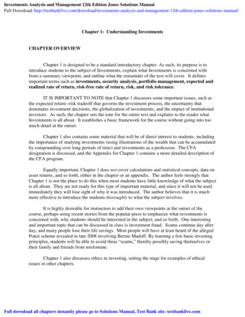
Downloaded by NASA LANGLEY RESEARCH CENTRE on June 23, 2015 http://arc.aiaa.org DOI: 10.2514/6.2015-1892A. Ablator Response ModelingThe objective of this task is to advance the state-of-the-art in ablative material modeling. The current state ofthe art of ablative material modeling remains codes derived from the Charring Material Ablator (CMA) code fromthe 1960’s (Ref. 8). Analysis is typically conducted in one spatial dimension and assumes simple thermochemicalequilibrium models for both the decomposition of resin and surface kinetic processes. While these codes tend to giveconservative results of actual material performance, suitable for engineering design, they are inadequate for detailedanalysis of post flight data from most NASA entry missions, which occur in a flight regime where nonequilibriumeffects are important. Analysis of the data returned from the Mars Science Laboratory (MSL) Entry, Descent andLanding Instrumentation (MEDLI) project in 2012 highlighted these issues and demonstrated the need for newresponse models with higher physical fidelity.9 It should be noted that the primary impediment to the advancementof the state of the art in material response modeling has been the perception in the community that validation of highfidelity models is not possible, and therefore it is pointless to include them in a simulation. It is this mindset that ledthis task to include a large experimental validation component, with a focus on innovative techniques to conductcomponent level validation of the new models being employed, supplemented with system level validation of theresulting codes using flight data from MEDLI and other sources.Initial efforts have been focused on low-density carbon/phenolic composites, with a specific emphasis onPhenolic Impregnated Carbon Ablator (PICA), given its extensive use by NASA for resent and planned missions. Asthe modeling of low-density carbon-phenolic becomes mature enough to allow technology/expertise transfer,investigations into other materials will gradually be initiated. The modeling strategy follows three interdependentthrust areas: (1) develop a general-framework volume-averaged physics-based model and implement the overallmodel in a research computational platform, verify the tool, and run sensitivity analyses with theoretical materialsproperties, (2) independently develop for each phenomenon detailed physics-based models for real materials, (3)carry-out and coordinate component validation studies focused on key physical models.Figure 1. Ablative response of a low-density carbon/phenolic composite.10A conceptualized volume-averaged mathematical framework of a multi-scale model for low-densitycarbon/phenolic ablators is shown in Fig 1.10 This model is being implemented in a new material response code thatis specifically designed to enable easy model development and analysis: the Porous material Analysis Toolbox basedon OpenFOAM (PATO).10 PATO is a fully portable OpenFOAM library written in C . As compared to current
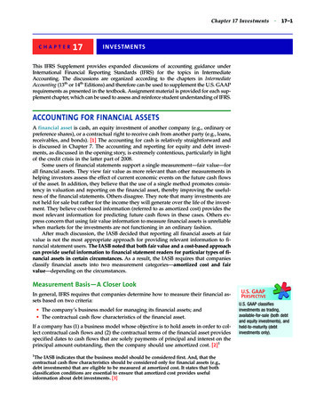
Downloaded by NASA LANGLEY RESEARCH CENTRE on June 23, 2015 http://arc.aiaa.org DOI: 10.2514/6.2015-1892state-of-the-art models (denoted as Type 1 in Fig. 1), the following additional volume-averaged conservationequations have been incorporated in PATO: non-pyrolyzing solid mass conservation (in-depth coking and ablation),species conservation including multi-component diffusion in finite-rate chemistry conditions, momentumconservation in porous media (via Darcy’s Law) using accurate gas (viscosity) and geometrical properties (tortuosityand permeability), and upgraded energy conservation. In a more recent upgrade,11 volume-averaged elementconservation including multi-component diffusion in equilibrium chemistry mode was added to allow modelingaccurately arc jet test samples under the conservative equilibrium assumption (allowing boundary layer gas flowwithin the sample and mixing with pyrolysis gases). PATO is now the most advanced research code for theimplementation of high-fidelity ablation response models. Verification and validation of PATO is ongoing, withsample cases developed in conjunction with the NASA/AFOSR Ablation Workshop series.The task also undertakes, oversees and collaborates on a series of component model validation experimentsconducted in house, at Universities across the country, and other national laboratories. At the current time the ESMproject is managing active collaborations with grantees in the NASA EPSCOR program, Space TechnologyResearch Grants program, Space Technology Research Fellowships, Early Stage Innovation program, and withLawrence Berkeley National Laboratory. A summary table of the experiments/actions in progress is available, andcan be provided upon request. The remainder of this section briefly highlights some of these studies; see Refs. 10-18for more detail.A model for the decomposition of phenolic resin has been implemented into PATO, and the importance ofaccounting for finite rate chemistry effects has arguably been demonstrated.10 In order to determine the elementaland molar composition of pyrolysis gases, batch reactor experiments have been carried out. The experimental setupshown in Fig. 2a was used to study the decomposition of a generic polymer and to quantify gas species productionby state-of-the-art gas chromatography analysis.14Figure 2. a) The Aerodyne batch reactor system for phenolic decomposition experiments. b-d)Amount of pyrolysis products measured using gas-chromatography.14
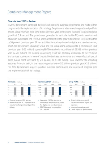
From the analysis of phenol-formaldehyde decomposition products, presented in Fig. 2b-d, the followingconclusions are drawn:Downloaded by NASA LANGLEY RESEARCH CENTRE on June 23, 2015 http://arc.aiaa.org DOI: 10.2514/6.2015-18921) Water is the main product below 800 K2) Light hydrocarbons have peak production at 1000 K3) Aromatic products are produced between 700 and 850 KAnalysis of liquid products from these experiment will be presented in a forthcoming publication.17 The ablatorresponse model activity has also recently concluded a series of elemental decomposition experiments using PICAsamples,18 and is finalizing the design of an upgrade to the reactor setup that will enable the study of the cokingphenomenon and the finite-rate chemistry of pyrolysis gases flowing through high temperature carbon preform. Theupgraded reactor is currently being manufactured.The modeling of heterogeneous chemistry is a key feature for physics-based simulations of carbon/phenolicablators. Characterizing the decomposition of carbon fibers in the presence of oxygen is needed to deriveheterogeneous reaction rates used as input to the mass conservation equation for the solid phase. A preliminaryvalidation effort, dedicated to determining the effective fiber reactivity, has demonstrated the capability of PATO topredict surface recession of Fiberform.10 This study covers temperatures from 700 to 1300 K and pressure between1.6 and 60 kPa and spans two experimental campaigns performed in the flow-tube reactor facility at NASA Ames. Afirst campaign has been conducted using hollow cylindrical FiberForm samples inserted in the test section of thetubular reactor.13 The test gas (air) was flown through the hollow samples, progressively ablating their inner walls.A second campaign used full cylindrical samples that plugged the side-arm tube, forcing the flow to percolatethrough the porous medium. 15 The performed studies led to the following observations/conclusions.1) Oxidation decomposition of carbon fibers manifests in the form of a pitting of the fiber surface that weakensthe fiber structure (see Fig. 3, from Ref. 13)Figure 3: Scanning electron micrographs of a) virgin and b) oxidized FiberForm.132) Impurities detected in Fiberform can act as catalyzing agents for C-fiber/O2 reactions enhancing oxidation andaccelerating the decomposition of the material.3) Thiele number analysis showed that most of the oxidation processes in flow-tube reactor conditions occur in areaction limited (volume ablation) regime. This suggests the need to determine in-depth material properties asa function of oxidation, especially density profiles.In order to address the lack of high-fidelity three-dimensional information on the fibrous architecture ofcarbon/phenolic ablators, the Project introduced the use of synchrotron X-ray microtomography to study highlyporous heat shield materials.12,16 Over the past two years we have collaborated with the Advanced Light Source(ALS) beamline at the Lawrence Berkeley National Laboratory synchrotron facility. The use of a synchrotron X-raysource has resulted in 3D images of the fibrous structures carbon/phenolic materials with micron-scale resolution,
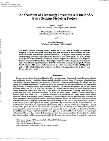
Downloaded by NASA LANGLEY RESEARCH CENTRE on June 23, 2015 http://arc.aiaa.org DOI: 10.2514/6.2015-1892low noise and very high quality. An example of image rendering, rebuilt from ALS data, is presented in Fig. 4 forFiberForm and Mersen CALCARB CBFC, used as structural materials for PICA and PICA-X (the Space-X variantof PICA) respectively. The images reveal detailed features such as hollow fibers for FiberForm (not known prior tothis work) and the presence of fiber clusters and bundles for both materials. More recently, X-ray tomography ofPICA has demonstrated the ability to image not only the fibers, but also the void filling phenolic resin. Tomographyexperiments have also been conducted in support of the CA-250 conformal and HEEET woven TPS products in theTPSM Project.Figure 1. Volume rendering of a 10003 voxel tomography of a) FiberForm and b) CALCARB.Pixel size is 0.325 µm in each image.16In addition to providing direct insight into the internal structure of ablators, the microtomography images arealso used to estimate quantitative material properties for high fidelity modeling such as specific surface area,tortuosity, and porosity.12 Figure 5a shows the distribution of surface area versus the grey-scale level of each voxelswithin a microtomography image. The resulting image is rendered as “solid” or “void” using a cut-off value range todifferentiate between the two. Once it is known where in the volume the voids are, quantities such as tortuosity (Fig.5b) can be computed via statistical analysis. The recent acquisition of GEODICT software is expected to greatlyfacilitate the evaluation of material parameters from such datasets.Figure 2: a) Specific surface area of carbon fibers as a function of the gray-scale cut-off, andb) distribution of the shortest path from one side of the FiberForm volume to its opposite side,computed using a cut-off pixel value of 80 (Ref. 12).
Downloaded by NASA LANGLEY RESEARCH CENTRE on June 23, 2015 http://arc.aiaa.org DOI: 10.2514/6.2015-1892One focus of the microtomography work is to analyze PICA, FiberForm and AQ61 samples in their virgin stateand others that have been extracted from test models oxidized in the Ames flow-tube reactor facility (in both air andCO2) and that have been exposed to high enthalpy plasma testing. This will allow the evaluation of changes inmaterial properties as the materials decompose. Results from this work have not yet been published, but will bepresented in upcoming papers.In order to handle the large datasets ( 1 gigavoxel) generated from X-ray microtomography, we have started thedevelopment of a computational platform for the analysis of tomographic datasets and for performing numericalsimulations of material and flow properties called the Porous Material Analysis (PuMA) toolbox. PuMA is currentlyable to import tomography data or internal generate a representative fibrous geometry, perform basic imageprocessing to assist in 3D rendering, and compute statistics-based material properties as surface area and porosity(Fig. 6a). PuMA has also been implemented in a simulation library that is able to model the microscale oxidation ofcarbon fibers using a sticking probability technique for the surface oxidation reactions and a marching cubealgorithm for tracking the fiber recession, similar to that proposed in Ref. 19. Figure 6b shows an example of amicroscale surface ablation simulation of FiberForm, in which the fibers near the surface (top of the figure) havethinned due to oxidation. Results from this new simulation capability will be shown in a future paper.Figure 6. a) Schematic of the current PuMA structure and b) Tomography-based PuMAsimulation of the surface oxidation of FiberForm.Figure 7. DPLR-ARM simulation over SPRITE geometry.22
Downloaded by NASA LANGLEY RESEARCH CENTRE on June 23, 2015 http://arc.aiaa.org DOI: 10.2514/6.2015-1892Finally, a new effort began in 2014 to develop an engineering ablation response model (ARM) based on thedata structure and solution algorithms inside the Data Parallel Line Relaxation (DPLR) code.20 As a first step, onlythermal conduction was modeled, with the intent of expanding the capabilities to include full ablative materialresponse. The material response equations were implemented within the DPLR framework to produce a structuredsolver and applied to compute the coupled fluids-material response simulation over the Small Probe ReentryInvestigation (SPRITE) geometry21 at Mach 7.1 conditions representative of an arc jet test.22 Figure 7 shows asnapshot of the coupled simulation showing Mach number contours in the fluid domain and temperature contours inthe solid domain. Although the preliminary results were promising, the work clearly demonstrated the difficultiesinherent in adapting an existing code and set of data structures to an entirely new set of governing equations andintegration procedure. As a result of this work, as well as the success demonstrated by coupling independent codesvia the libMesh framework (see next section), it was decided to stop development of the DPLR-ARM and focus on anew standalone engineering ARM beginning in 2015.B. Ablator Response CFD CouplingCFD-ablation response coupling has been attempted by many previous authors, and results have been presentedfor multiple geometries, typically using a loosely coupled approach in which the steady state CFD solution is used todrive a material response calculation, the results of which are fed back into the CFD. The objective of this effort wasto obtain a tighter degree of coupling, and to do so in a way that would be generally applicable to many availableCFD codes and ablation response models. In order to facilitate a standardized data transfer process, the C librarytool libMesh23 was chosen, and coupling was demonstrated using libMesh between three different CFD solvers andthe CHAR24 and TITAN25 ablation response codes.As a first step, the CFD code FINS26 was coupled to CHAR,27 completing work that had begun prior to thebeginning of the ESM project. This code served as the pathfinder application and demonstrated the utility of thelibMesh C library. DPLR was then converted from a standalone executable into a callable subroutine. The meshfree interpolation routines from the libMesh libraries were incorporated into the code to pass boundary data betweenDPLR and CHAR. Initial development was performed on a two dimensional version. A central “handler” code wasdeveloped to run DPLR and CHAR in an iterative manner and facilitate boundary data transfer between them. Thecoupled DPLR-CHAR code was applied to a conduction-only problem over a 45 sphere cone with a freestreamvelocity of 5.92 km/s. The solid body consisted of an external layer of copper on top of a layer of aluminum. TheDPLR-CHAR results were then compared with FINS-CHAR. Temperature contours through the shock layer andsolid are shown in Fig. 8. The in-depth temperature contours are in good agreement, indicating properimplementation of the boundary data transfer in both codes. The differences in the solid temperature contours aredue to slightly different surface heating rates computed by DPLR and FINS.28(a)(b)Figure 8. Temperature contours through the fluid (a) and solid (b) comparing DPLR-CHAR and FINSCHAR results.28Next, DPLR was coupled to the TITAN code,29 a 2D/axisymmetric ablation response solver. The coupled codewas applied to arc jet flow over an iso-q geometry constructed of PICA. The DPLR-TITAN results were comparedagainst previous TITAN values and against arc jet experimental data on surface recession rates. Figure 9 shows
Downloaded by NASA LANGLEY RESEARCH CENTRE on June 23, 2015 http://arc.aiaa.org DOI: 10.2514/6.2015-1892temperature contours in both the external flowfield and inside the solid iso-q geometry after the model had beenexposed to the flow for 27 seconds. The coupled DPLR-TITAN code predicted the surface recession rates to within8% of the experimental measurements.28 The DPLR-CHAR implementation has since been extended to fully threedimensional simulation; results will be presented at a future conference.(a)(b)Figure 9. Temperature contours for iso-q simulations, (a) External
Reference Architecture 5.0 (Ref. 2) in 2009, the Mars EDL Systems Analysis Study3 in 2009-2010 and the current Human Spaceflight Architecture Team (HAT). The crux of the problem is that 1970s-era Viking heritage EDL technologies used for all Mars missions to date, including the Mars Science Laboratory,4 are not extendable to