Transcription
Database FundamentalsByunggu Yu, PhDComputer Science and Information TechnologyUniversity of the District of ColumbiaBldg. 42, Suite 1124200 Connecticut Ave. NWWashington, DC 20008Phone: (202) 274-6289byu@udc.eduThis article is primarily targeting people who have some knowledge in Computer Science orInformation Technology or those who meet the prerequisites for a senior database course. Alsotargeted are those who have some database experiences but need to refresh/expand theirdatabase knowledge or those who need concise references.Original submission on March 22, 2008First Revision on Aug 10, 2008Second Revision on December 5, 2008Final Revision on Feb 10, 2009
Outline1. Introduction2. What is a Database System?3. Database Models3.1 The Network Model3.2 The Hierarchical Model3.3 The Relational Model3.4 The Object-oriented Model and Native Query4. Database Design: The Three-Step Approach4.1 Step 1: Application Requirements to Conceptual Design4.1.1 Entity Set4.1.2 Relationship Set4.1.3 Weak Entity: A Concept of Nested Entities4.1.4 Specialization & Generalization: A Concept of Inheritance4.1.5 Aggregation: A Concept of Entity Composition4.1.6 Example4.1.7 Remarks4.2 Step 2: Conceptual Design to Logical Design4.2.1 Basic Components4.2.2 Conversion Process4.2.3 Example4.2.4 Remarks4.3 Step 3: Logical Design to Normalized Database4.3.1 Functional Dependency4.3.2 The First Three Normal Forms4.3.3 Boyce-Codd Normal Form (BCNF)4.3.4 Example4.3.5 Higher Normal Forms4.3.6 Remarks5. Database Queries5.1 Storage: Database Schema Manipulation5.2 Update: Database Instance Manipulation5.3 Retrieval5.4 Additional Features6. Database Optimizations7. Database Support for New Emerging Applications: Spatiotemporal Applications8.1 Related Research8. ConclusionReferencesKey Words: databases, database design, database system, spatiotemporal databases
Database FundamentalsAbstractFrom personal email clients to enterprise and government information systems, moderncomputer applications deal with increasingly large amount of data. Accordingly, there is anever increasing demand for efficient and reliable technology for managing large collectionsof structured data (databases). This article provides readers with a comprehensive overviewof modern database technology. Practical database development methods are presented alongwith necessary details of related concepts and theory. The following topics are covered:definition of modern database systems, standard database models, database design anddevelopment, performance and scalability issues, and emerging application concepts formanaging continuously moving or changing data.
1. IntroductionIn today’s computing world, more and more applications -- ranging from personal programs,such as personal file managers and email clients, to enterprise and government serverapplications -- deal with increasingly large data.A database is a collection of structured and organized data. Examples include a set ofmessages in a certain form (e.g., an email form of sender, recipient, subject, and message bodyfields), a set of student records, and a set of medical records with associated patient andinsurance data, to name a few. To efficiently and reliably manage large databases, carefullydesigned computer application software is necessary. This software is called a databasemanagement system (DBMS).A database system is a complete computer application system consisting of databases, adatabase management system (DBMS), application programs interacting with the DBMS, andhuman users interacting with the application programs. For efficiency and reliability, moderndatabases are systematically structured and organized in standard database models.Modern database technology has been developed through decades of rapid evolution -electronic databases have been in use since the advent of electronic computer systemsequipped with some storage for programs and data.Modern general-purpose computers (beginning with DEC’s PDP series and IBM 360) evolvedduring the mid-1960s through the early-1980s. This is an important era of modern electroniccomputing: computer systems began to be widely distributed with more storage space andcomputing capabilities, supporting both data-intensive and computation-intensive applications.Accordingly, important modern computing concepts, such as general-purpose operatingsystems (UNIX), multiprogramming, random-access storage, spooling, and timesharing, weredeveloped through this period. These key concepts and technologies provided a strong basis forthe current generation of multitasking computers.As the computers grew in popularity and capability, more data-intensive applications (ordatabase applications) required reliable, robust, and secure mechanisms for managing andsharing large collections of complicated data. Early custom and ad hoc database managementapproaches were found to be easily defective due to several difficulties.For example, suppose that one developed a student database application originally for anacademic department at a university. If the program manages student data, such as names,majors, identification numbers, addresses, advisors, telephone numbers, and email addresses,in custom-made files, it will certainly be challenging for any others developing another studentdatabase application for the university’s registrar’s office to access the data (data sharing) andto manage the registrar’s own portion of the data in such shared files in a protected and securemanner (data protection and security). Should the two applications end up with two differentcustom-made data sets (files), the department’s students must be stored in both data sets (dataredundancy). Then any changes on the student side must immediately be reflected on bothdatabases, otherwise, this data redundancy results in data inconsistency (e.g., two differentemail addresses of a student: one is up-to-date and the other is old and not valid).These challenges gave birth to modern database standards.
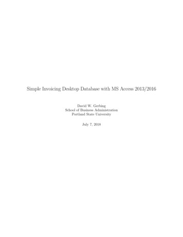
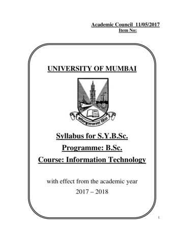
This article provides readers with a comprehensive overview of modern database technology.Standard database development methods are presented along with necessary details of relatedconcepts and theory.The organization of the rest of this article is as follows: Section 2 gives a brief definition ofmodern database systems; Section 3 introduces major standard models for databaseexpression and sharing; Section 4 provides a good database development practice, addressingdata redundancy, inconsistency, protection, and security; Section 5 gives a review on theubiquitous SQL, a practical standard database language for database implementation and use;Sections 6 and 7 address the performance and scalability issues; Section 8 provides somecurrent and future trends in the area of database research and practice.2. What is a Database System?A database system is a computer application system consisting of one or more databases(collections of structured and organized data), a database management system (DBMS)managing the databases, one or more database application programs interacting with theDBMS to access the databases, and human users or other applications that interact with thedatabase application programs. (Physical database storage is outside the scope of this article. Interestedreaders are referred to [Kim, Yu, and Chang, 2008].)All database application programs must indirectly access the databases only through the DBMS(by calling the data access and management functions of the DBMS). This is for ensuringperformance optimization, protection, and security of the system and its data.Typically, database system users are categorized into end users, applicationdevelopers/programmers, database management system developers/programmers, anddatabase administrators. Modern DBMSs recognize such different user types in order to supportdifferent roles of the user groups for enhanced protection and security.Figure 1 shows a modern database system. An instance of a database system consists of thedatabases as well as the runtime instances (processes; programs in execution) of the DBMSand application programs.Human usersOther applicationsDatabase Application ProgramsDatabase ManagementSystemDatabasesFigure 1. Database system architecture
A particular method used for structuring or organizing data within a database is called adatabase model. A database model specifies (1) a set of structure types, (2) the associatedoperations, (3) a set of rules according to which consistent database states and changes aredefined and maintained. A database management system (DBMS) is built on a particulardatabase model. Popular database models and recently reviving legacy database models(through object-oriented concepts) are introduced in Section 3.3. Database ModelsDuring the earliest period of electronic computing and programming, ad hoc style custom-madedatabases were created and managed by individual application programs. Standard databasemodels and general purpose database management systems were nonexistent.In the 1960s, the capability and popularity of electronic computers increased along with moreapplications dealing with large amount of data, demanding a general purpose database modelthat can provide a basis for data sharing and consistency control mechanisms as exemplified inSection 1.To meet this growing demand for a standard database model, Charles Bachman and hiscolleagues formed Database Task Group within CODASYL (Conference on Database SystemsLanguages) to develop a database model, based on Bachman’s IDS (Integrated Data Store), anearly database engine developed at General Electric in the early 1960s. In 1969, CODASYLdeveloped the first version. In 1971, CODASYL delivered a second publication, which becamethe model basis for some early DBMSs, such as IDMS. This modeling effort continued into the1980s. This database model is commonly called the “Network Model” [CODASYL, 1971] anddatabases based on this model are called network databases. The Network Model is explainedin Section 3.1.Although the CODASYL’s standardization effort and its final ISO specification producedsubstantial scientific impact, its popularity in commercial database software industry was notdominant. In the late-1960s, IBM used the “Hierarchical Model” [Bjorner and Lovengreen, 1982],which was a basis for the development of IMS (IBM Information Management System) and DL/I(Data Language 1), used in the Apollo program in part. IBM’s IMS and its transaction managerare still in active use in the financial industry [IBM 2008]. The Hierarchical Model is explained inSection 3.2.Although not the mainstream database model, the concepts of the Hierarchical Model and theNetwork Model (now also collectively called the navigational database models) have beenapplied in many data and information systems including knowledge information systems,XML/XPath, DOM (Document Object Model), and Web services, where procedural datanavigation operations [Bachman, 1973] are dominant.Another model, which became the mainstream model for most modern disk-based, generalpurpose DBMSs, such as Oracle, DB2, Informix, MySQL, and SQL-Server, is the “RelationalModel”. The Relational Model was originally proposed by E.F. Codd in 1970 [Codd, 1970]. TheRelational Model and the object-oriented concepts are discussed in Sections 3.3 and 3.4,respectively.
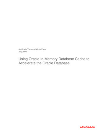
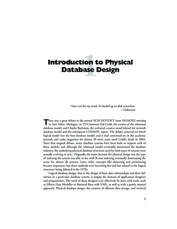
The following two generic definitions might help some readers:Set: a set is a collection of objects of the same type. For example, a student set of id, name,major, and age is a collection of student objects (representations) each of which has a certainvalue on each of the attributes (i.e., id, name, major, and age).Mapping Cardinality (n-to-m relationship): when there is an n-to-m relationship (or a mappingcardinality of n-to-m) between two sets S1 and S2, both of the following conditions hold: (1) anobject in S1 can be associated with (or linked to) m objects in S2; (2) an object in S2 can beassociated with (or linked to) n objects in S1. Note, n and m can be any positive integers. Whenn and m are not specified, it means that they can be any positive integers.3.1 The Network ModelIn the Network Model [Bachman 1973; CODASYL 1971; Silberschatz et al., 2005a], a databaseconsists of records and sets. A record represents a concrete entity in the real world. Everyrecord is an instance of a certain record type and has a unique database key (DBK). A recordtype is a named definition of all permissible occurrences of records of a certain type. A recordtype consists of named items (fields) that are either element items or a named group of otheritems. Figure 2 gives an example of a record type and two yeeJeffersonTom321 Small St,Red City123 Karen Ave,Green City 50,000 100,000CoordinatorDirectorWagePositionFigure 2. Record type and recordsThe main structuring concept of the CODASYL Network Model is the set (or data set), which isa one-to-many relationship between two record types. Each set is named and includes onerecord of the first record type (Owner) and 0, 1, or more records of the other record type(Members). It is allowed for a record type to take the roles of both owner and member in a set.Each set is ordered (i.e., ordered set of records), and the sequence of the records can conveysome information.In contrast to the Hierarchical Model, which is explained in Section 3.2, the Network Modelallows records to participate in multiple sets. For example, if a record participates in two setswith two different owners, the record has two owners, breaking the tree-like hierarchy whereevery node (record) has strictly only one parent (or owner) except for the root. This results inmore general (less restrictive) network structures.The data-structure (database schema) diagram of CODASYL DBTG (Database Task Group)1971 standard includes record type node, many-to-one link, and link node (a.k.a. Rlink). Rlink isa non-data node that may have a single field of system generated unique identifier. This wasintroduced to represent many-to-many relationships and n-ary relationships. A network node is
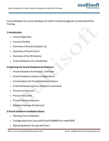
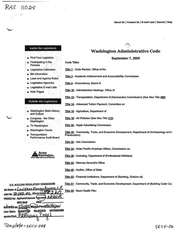
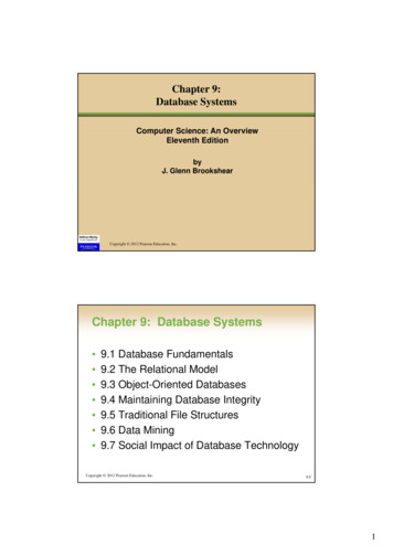
represented as a box; a link is represented as a line with an arrow pointing to the one side of therelationship. Figure 3 shows an example of a Network Data-Structure Diagram (a simpledatabase schema in the Network Model): The Rlink represents the many-to-many relationshipbetween Customer and Account using two many-to-one links.CustomerAccountcustomerID customerNameaccountNumber gure 3. Network-structure diagramIn most early DBMSs based on the Network Model, database keys are physical addresses ofthe records in the storage. Moreover, each set is implemented in the form of linked list or tree inthe storage. These closely tied logical data description and physical data description contributedto the high efficiency of data retrieval, but also made some maintenance and restructuringoperations rather expensive.3.2 The Hierarchical ModelIBM developed a DBMS system, IMS (Information Management System) [IBM, 2008], based ontheir implementation of the Hierarchical Model and DL/I (Data Language 1). The HierarchicalModel [Bjorner and Lovengreen, 1982] is generally similar to the Network Model, except that norecord can have more than one parent in the structure, which is the main conceptual difference.One can represent a network of entities by duplicating entities. However, this duplication(redundant data) can cause data inconsistency problem. Thus, there has been a claim in favorof the Network Model, in comparison to the Hierarchical Model: the Network Model allows amore natural modeling of relationships between real entities in knowledge representation.Like the Network Model, the tree-structure diagram (database schema diagram) of theHierarchical Model consists of nodes and arrowed lines. However, a tree-structure diagrammust be organized in the form of a rooted tree. Figure 4 shows a tree-structure diagramcorresponding to the schema shown in Figure 3.
CustomercustomerID customerNameAccountaccountNumber essDateTimelastAccessDateTimeAccountaccountNumber balanceCustomercustomerID customerNameFigure 4. Tree-structure diagramIn the IBM Hierarchical Model, a database is a tree (hierarchy) of nodes called segment, whichis the smallest retrieval unit. Segment is similar to the concept of record in the Network Modeland consists of one or more fields (items in the Network Model). IMS stores segment trees onIBM’s hierarchical file systems, such as ISAM, VSAM, HSAM (Hierarchical Sequential AccessMethod), and HDAM (Hierarchical Direct Access Method).IMS has transaction management capabilities called IMS TM typically supporting IMS networkdatabases as well as IBM’s relational databases (DB2 introduced in 1982).3.3 The Relational ModelThe Relational Model for database management was proposed by Edgar Codd in 1969 and1970 [Codd, 1972]. This model enables the application programs and users to expressdatabase queries and integrity constraints by describing “what” they want, without “how” tonavigate the database to achieve it.For example, to retrieve every employee whose age is less than 30, instead of writing aprocedure of navigation and selection (or find-and-get) steps, one can simply say “report everyemployee e whose age is less than 30” or {e e employee (e.age 30)}.Informally speaking, the term “relation” and “relational” respectively mean “table” and “based ontables”: a database is a set of tables. Normally, in a relational database, every table is linked toone or more other tables in the same database. A table can also be linked to itself. Unlike someearly implementations of the Network Model and the Hierarchical Model, the Relational Modelcompletely separates a “logical database” from its physical implementation (the actual databaserepresented in the platform’s physical storage) by providing a complete basis for a logicalrepresentation of the database. This basis can also support the applications’ different andsecured “views” of the same database.For example, considering a university database, an academic department’s view, the registrar’sview, and the research office’s view are all different, but each of these represents a customized(and possibly reorganized) subset of the whole database that is systematically structured,shared, and managed for consistency. This multi-level data independence provides muchsecurity, flexibility, accessibility, and database migration facilities. This advantage increased thepopularity of the Relational Model in many application domains. Historically, this dataindependency has provided the database community with an open opportunity to contribute tothe technology development by devising efficient physical database implementations and
mappings between the different levels (physical data organizations, indexing methods, andquery processing techniques), increasing its popularity in relevant research communities.Importantly, the mathematical foundation of the Relational Model was implemented and hasbeen matured, resulting in the dominant mainstream database products and applications,collectively called SQL (Structured Query Language) database systems.SQL query capability, which is largely based on the Relational Model, is currently themainstream database technology. Although still far from perfection [Date and Darwen, 2000],this has been tried and found to be reliable, robust, and flexible enough to support ad hocqueries as well as predefined queries to some good extent.Traditionally, the relational database approach has used Entity-Relationship (ER) Model [Chen1976] to represent a database schema diagram. Figure 5 shows a basic example correspondingto the diagrams shown in Figures 3 and ameAccountbalancelastAccessDateTimeFigure 5. Entity-Relationship diagramThis model and more recently developed alternatives are extensively discussed along with thedetails of the Relational Database Model in Section 4.3.4 The Object-oriented Model and Native QueryThe Object-oriented Model [Date and Darwen 2000; Silberschatz et al., 2005c] and itsimplementations became major issues over the 1980s and the 1990s as the object-orientedprogramming languages became popular.Object-oriented databases (or simple object databases) are primarily designed to work withobject-oriented programming languages such as C , Java, C#, Python, and some proprietarylanguages. ODBMSs (Object or Object-oriented Database Management Systems) use the exactsame object-oriented model (including type system, object encapsulation, inheritance,composition) as the supported object-oriented language(s).Consequently, the database schema representation of the Object-oriented Model adopted UML(Unified Modeling Language) that is intended, in part, to unify past experience about objectoriented software modeling techniques. UML is a large modeling language consisting of at least11 diagrams. Particularly, Class Diagram, which represents the static structural view of objectoriented software, is popular in object-oriented database schema design.
In Class Diagram, the main constituents are “class” and “relationship”. Class represents a set ofthe same type objects (instances). A class has three components – name, data attributes, andoperations. Note that, unlike the other models, the Object-oriented Model can represent theoperations (the static behavior aspects) of data objects. As in the modern ER model (discussedin Section 4.1), the relationship is enhanced by various constraints and further categorized intoassociation, generalization, realization, and various kinds of dependency. Figure 6 shows asimple example of UML Class Diagram corresponding to the ER diagram shown in Figure 5.Interested readers are referred to [Rumbaugh et al., ame:stringaccountNumber:integerbalance:realdeposit (amount)withdraw (amount)changeBalance teTime()Figure 6. UML class diagramWell-developed ODBMSs provide their supported object-oriented programming languages withcore database capabilities including persistent object storage, consistency control mechanismsfor concurrent accesses to the objects, transaction and recovery, navigational and declarativequeries, and other database capabilities.During the late 1990s and the early 2000s, object-oriented database standards for Java (ODMGJava Language Binding), which is part of ODMG (Object Data Management Group) standard3.0, became popular. In 2001, many members of the ODMG decided to focus only on the JavaData Objects specification, and the ODMG disbanded.More recently, in 2006, the Object Management Group (OMG) formed Object DatabaseTechnology Working Group to develop a standard object databases specification based onODMG3.0 and other recent developments in the area of object databases.Object databases typically show the best performance for predefined (defined and programmedwhen the database was designed) navigational queries using the pointers connecting theobjects. Because of this, as the network and the Hierarchical Models, the Object-oriented Modelis categorized into the navigational models. However, recently developed ODBMSs, such asObjectivity/SQL , Cache, and Matisse, also support SQL (Structured Query Languageoriginally developed based on the mathematical foundation of the Relational Model) to somelimited extent.
Although most object-oriented database management technologies (products) are based on thetraditional C object oriented concepts and/or the Java part of the ODMG 3.0, the standardbasis for pure object-oriented databases is relatively weak, compared to the strong basis of therelational databases. Unlike the Relational Model, the object model has a lack of mathematicalfoundation. Because of this, pure object-oriented query language standardization efforts havenot resulted in a complete standard. Recently, an alternative solution has been investigated:instead of introducing an additional database language, one can use the object-orientedprogramming language itself to express queries in application programs (a.k.a. the nativequeries). Examples include Microsoft’s Language Integrated Query, a database query extensionto C# and .NET.Switching from an SQL DBMS to a purely object-oriented DBMS means you lose the capabilityto create sound and complete SQL queries and its mathematical basis for retrieving ad-hoccombinations of data, even though many newer commercial object-oriented databases are ableto process SQL queries to a limited extent.Much of the object database ideas were also adopted in recent SQL standards [ISO 1999; ISO2003], which is currently supported by mainstream relational DBMSs (now called objectrelational DBMSs).4. Database Design: The Three-Step ApproachThis chapter provides a guided tour in developing an application system based on a mainstreamSQL DBMS. It is recommended that interested readers apply the techniques introduced in thischapter to other object-oriented database management systems, such as CACHE, that supportboth pure object-oriented concepts as well as the mathematical Relational Model basis. Forapplication-specific pure object-oriented applications, since database objects are managed asprogram objects and since database queries and navigations are expressed in the nativeprogramming languages, interested readers are recommended to follow the well-establishedand up-to-date Unified Modeling Language (UML) approach as well as a specific object-orienteddatabase management product’s specifications.Given a database application requirement (written verbally in natural human language) and aDBMS, one can design a database schema (structure) and pre-determined queries to build adatabase system. This section (Section 4) introduces a professional database schema designtechniques. Database query and some logical database optimization steps are discussed later.4.1 Step 1: Application Requirements to Conceptual DesignThe first step of the database design process is reaching an agreement with the requirementissuers on the interpretation of the original requirement and necessary assumptions. For this, avisual language that can visually and intuitively express the concepts/views of the databasedesigner is required for systematic interpretation of the original requirement. The primary goalsof this conceptual design process are finding and clarifying all potential ambiguities andnecessary assumptions with the customers.Popular languages for this purpose include UML (Unified Modeling Language) and the ERModel [Chen 1976]. This article uses an extended ER-model [Lyngbaek and Vianu, 1987;Markowitz and Shoshani, 1992], which supports some object concepts, such as inheritance andcomposition hierarchies. Interested readers are recommended to consider UML for pure object-
oriented database design purposes in order to model not only the structures but also thebehaviors of database objects in a supported object-oriented programming language.The key concepts of the ER-model are introduced through Sections 4.1.1 – 4.1.5. Then Section4.1.6 gives an example of converting an application requirement into an ER-diagram, aconceptual database schema. Section 4.1.7 gives section closing remarks.4.1.1 Entity SetAn entity is a concrete object (e.g., a person or a book) or an abstract object (e.g., a checkingaccount, a holiday, or a concept) in the real world that can be uniquely identified.An entity set is a set of entities of the same type that have the same properties (attributes). Inthe ER-model, an entity set is represented as a rectangle and each of its attributes isrepresented as an ellipse connected to the rectangle. Figure 7 shows an example of ERdiagram consisting of only one entity set.One or more attributes of each entity set is underlined -- Collectively, the underlined attributes ofan entity set form the primary key of the set. The primary key is the principle means ofidentifying entities within the set (i.e., every entity has a unique not-null value on the key). Adashed ellipse represents a derived attribute. The value "AVAILABLE CREDIT" in Figure 7 canbe derived (i.e., CREDITLINE – CURRENT BALANCE). Derived attributes need not be storedin the database, but can be computed at run-time in the application.NUMCREDITLINECURRENT BALANCECredit CardAccountAVAILABLE CREDITFigure 7. ER diagram of a single entity set4.1.2 Relationship SetA relationship is an association among several entities. An n-ary relationship r is an ordered ntuple (e1, e2, , en), where ei is a member of entity set Ei for 1 i n. This is read as “theentities e1, e2, ,en participate in relationship r”.A relationship set is a set of relationships of the same type that have the same properties. An nary relationship set R is {(e1, e2, , en), r-att e1 is a member of E1, e2 is a member of E2, , enis a member of En, r-att is a set of zero, one, or more attributes the participating entities share}.In the ER-model, a relationship set is represented as a rhombus (informally called diamonds)linked to participating entity sets (rectangles). Each of these links needs a careful and thoughtfulattention, and this process is one of the keys for finding potential ambiguities and necessaryassumptions that must be clarified by the issuer of the original application requirement.Figure 8 shows an example ER-diagram of binary relationship. In our version of the ER-modelused in this article, each linear line connecting a participating rectangle to the rhombus has one
or more integer ranges on it. In the case of binary relationship (i.e., a rhombus with twoconnected rectangles), a range represents the minimum and the maximum number of entities inthe corresponding rectangle (entity set) that can be associated with one entit
of modern database technology. Practical database development methods are presented along with necessary details of related concepts and theory. The following topics are covered: definition of modern database systems, standard database models, database design and development, performance and scalability issues, and emerging application concepts for